March 18, 2014
The purpose of this article is to familiarize users with the features of operation, installation and storage of tantalum capacitors. The article contains a description of the breakdown mechanisms of tantalum capacitors and offers an option for calculating permissible levels of operating currents and voltages for various frequency ranges.
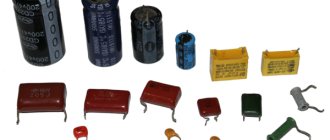
The electronics industry is moving towards smaller electronic devices and higher switching frequencies: over the past ten years, converter operating frequencies have increased from 10 kHz to 100 kHz and beyond. The requirement for high operating frequencies and small dimensions lead to an increase in the use of solid tantalum capacitors. Solid tantalum capacitors have excellent characteristics: high specific capacitance, small dimensions (Figure 1, Table 1) [1]. The ESR value of such capacitors remains unchanged with increasing frequency or even decreases, and the impedance value at frequencies of 100 kHz and above reaches a minimum value. In addition, they are highly reliable and compatible with all common installation technologies.
Figure 1 – Dimensions of tantalum chip capacitors
Table 1 – Dimensions of generally accepted standard sizes of tantalum chip capacitors
| Standard size | Dimensions inch [mm] | |||||
| L | W | H | P | TW | TH (min.) | |
| 0.126 ± 0.008 | 0.063 ± 0.008 | 0.063 ± 0.008 | 0.031 ± 0.012 | 0.047 ± 0.004 | 0.028 | |
| [3.2 ± 0.20] | [1.6 ± 0.20] | [1.6 ± 0.20] | [0.80 ± 0.30] | [1.2 ± 0.10] | [0.70] | |
| 0.138 ± 0.008 | 0.110 ± 0.008 | 0.075 ± 0.008 | 0.031 ± 0.012 | 0.087 ± 0.004 | 0.028 | |
| [3.5 ± 0.20] | [2.8 ± 0.20] | [1.9 ± 0.20] | [0.80 ± 0.30] | [2.2 ± 0.10] | [0.70] | |
| 0.236 ± 0.012 | 0.126 ± 0.012 | 0.098 ± 0.012 | 0.051 ± 0.012 | 0.087 ± 0.004 | 0.039 | |
| [6.0 ± 0.30] | [3.2 ± 0.30] | [2.5 ± 0.30] | [1.3 ± 0.30] | [2.2 ± 0.10] | [1.0] | |
| 0.287 ± 0.012 | 0.169 ± 0.012 | 0.110 ± 0.012 | 0.051 ± 0.012 | 0.094 ± 0.004 | 0.039 | |
| [7.3 ± 0.30] | [4.3 ± 0.30] | [2.8 ± 0.30] | [1.3 ± 0.30] | [2.4 ± 0.10] | [1.0] | |
| 0.287 ± 0.012 | 0.169 ± 0.012 | 0.157 ± 0.012 | 0.051 ± 0.012 | 0.094 ± 0.004 | 0.039 | |
| [7.3 ± 0.30] | [4.3 ± 0.30] | [4.0 ± 0.30] | [1.3 ± 0.30] | [2.4 ± 0.10] | [1.0] | |
| 0.287 ± 0.012 | 0.169 ± 0.012 | 0.079 max | 0.051 ± 0.012 | 0.094 ± 0.004 | 0.039 | |
| [7.3 ± 0.30] | [4.3 ± 0.30] | [2.0 max] | [1.3 ± 0.30] | [2.4 ± 0.10] | [1.0] | |
The main task when operating tantalum capacitors is to increase service life and reduce the number of failures. The analysis showed that this is only possible if their characteristics are taken into account at all stages of life: production, storage, installation, operation. In order to determine the reasons for the failure of tantalum capacitors, it is necessary to consider their design and production features.
Description and purpose of tantalum capacitors
Modern tantalum capacitors are small in size and belong to chip components that are designed for mounting on a board. Otherwise, such parts are called SMD, which stands for “surface mount components.” SMD parts are convenient for automated mounting and soldering processes on printed circuit boards.
The main purpose of electrolytic polarized tantalum capacitors is to act in conjunction with a resistor to process the signal and smooth out its peaks and sharp pulses.
Capacitors are widely used in automotive, industrial, digital, and aerospace applications.
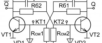
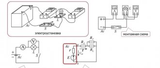
Designation in diagrams
In general, when repairing and re-soldering modern SMD printed circuit boards, it is most convenient when you still have a diagram at hand, looking at which it is much easier to understand what is installed, to find out the location of a certain part, because an SMD capacitor in appearance may not differ at all from the same transistor. The designations of these parts in the circuits remained the same as they were before the arrival of chips on the market, and therefore the capacity and other necessary characteristics can also be easily found by a radio amateur who has not encountered SMD components.
«>
Design of tantalum solid capacitors
The tantalum capacitor is an electrolytic type. It consists of 4 main parts: anode, dielectric, solid electrolyte, cathode. The manufacture of a tantalum capacitor consists of a number of rather complex technological operations.
Anode manufacturing
The porous granular structure is obtained by pressing from highly purified tantalum powder. During the sintering process under high vacuum conditions at temperatures of +1300...+2000°C, a sponge structure with a developed surface area is formed from the powder. Thanks to it, high capacity is ensured in a small volume. A tantalum capacitor, with the same capacitance as an aluminum device, has a much smaller volume.
Formation of the dielectric layer
A dielectric oxide layer is grown on the surface of a tantalum pentoxide anode through an electrochemical oxidation process. The thickness of the oxide can be adjusted by changing the voltage. Typically, the thickness of the dielectric film is a fraction of a micrometer. The oxide layer has not a crystalline, but an amorphous structure, which has significant electrical resistance.
Obtaining electrolyte
The electrolyte is a solid-state semiconductor - manganese dioxide - which is obtained by heat treatment of manganese salts during the redox process. To do this, the anodic sponge layer is coated with manganese salts, and then heated to obtain manganese dioxide. The process is repeated several times until the anode is completely covered.
Formation of the cathode layer
To improve contact, the electrolyte is coated with a graphite and then a metal layer. The metal usually used is silver. The formed composite is pressed into the compound.
Features of tantalum capacitors
- The available capacity of these radio components is from 1 to several hundred microfarads
- Relatively low equivalent series resistance (ESR) and lowest leakage. Thanks to these properties, tantalum capacitors work successfully in high-quality audio equipment, test and measurement instruments.
- A thin oxide layer that provides high dielectric constant. The combination of a large surface area of the sponge anode with good dielectric constant provides storage of a large amount of energy.
Unlike electrolytic capacitors, tantalum capacitors explode when overcharged or breakdown. The force of the explosion depends on the size of the capacitor and can damage both adjacent elements and the circuit board.
Video
A radio amateur who has encountered the type of SMD capacitor for the first time is perplexed as to how to understand all these “squares” and “barrels” if some do not have markings at all, and if there is one, you won’t understand what it means. But you want to keep up with the times, which means you still have to figure out how to determine the identity of a board element and distinguish one component from another. As it turned out, there are still differences, and the markings, although not always and not on all capacitors, give an idea of the parameters. There are, of course, SMD components without identification marks, but first things first. First you need to understand what this element is and what its task is.
This component works as follows. Each of the two plates located inside is supplied with opposite charges (their polarities differ), which tend to one another according to the laws of physics. But the charge cannot “penetrate” onto the opposite plate due to the fact that there is a dielectric spacer between them, and therefore, not finding a way out and not being able to “escape” from the nearby opposite pole, it accumulates in the capacitor until its capacity is filled.
Breakdowns of tantalum capacitors
When using these effective, but somewhat capricious devices, it is necessary to monitor the occurrence of a failure condition, since they have been known to catch fire when they fail. Failures are due to the fact that, if used incorrectly, tantalum pentoxide changes its amorphous structure to a crystalline one, that is, it turns from a dielectric into a conductor. A change in structures can occur due to too high inrush current. Dielectric breakdown causes an increase in leakage currents, which in turn lead to breakdown of the capacitor itself.
The cause of troubles associated with the operation of tantalum capacitors may be manganese dioxide. The oxygen present in this compound causes the appearance of local fires. Breakdowns with fire are typical for older models. New technologies make it possible to obtain more reliable products.
Breakdowns that occur at high temperatures and voltages can cause an avalanche effect. In this case, the damage often extends over most or all of the device. If the area of crystallized tantalum pentoxide is small, then a self-healing effect often occurs. It is possible due to the transformations occurring in the electrolyte in the event of dielectric breakdown. As a result of all transformations, the crystallized conductor site is surrounded by manganese oxide, which completely neutralizes its conductivity.
Criterias of choice
Capacitor CBB61
In today's market, it can be easy to get confused due to the different types and subtypes of chip capacitors available. They all differ in their characteristics, and each has its pros and cons.
The criteria for selecting specific types of devices are determined by the following factors:
- ability to work at high voltage;
- significant capacity;
- magnitude of breakdown voltage;
- self-inductance;
- stability and long-term work;
- price.
Due to their excellent characteristics, solid tantalum capacitors are very popular in the field of electronic equipment production.
Other defects of tantalum capacitors
In addition to breakdown, other defects occur in the capacitor as a result of incorrect production technology and violation of transportation and storage rules:
The first type of such defects can appear on the grown dielectric as a result of its sharp impact on a hard surface. The second is during the formation of an electrolyte layer due to the combined action of thermal shock and internal gas pressure in the pores.
If the production technology is violated, foreign substances may appear on the tantalum surface - carbon, iron, calcium, which lead to unevenness of the dielectric layer.
that appeared during the manufacture of the device. Crystallization can occur due to a discrepancy between the electrolyte composition and the technological requirements and incorrect temperature conditions of the process.
Tantalum polymer capacitors
Most of the problems characteristic of tantalum capacitors have been solved in tantalum-polymer analogues. Tantalum polymer capacitors use a conductive polymer instead of manganese dioxide as the electrolyte. It gives minimal ESR, which allows much higher currents to pass compared to tantalum predecessors. Tantalum-polymer devices are successfully used as smoothing capacitors in power supplies and voltage converters.
The conductive polymer provides low sensitivity to current pulses, resistance to external factors, lack of structure degradation, and a longer service life. The high stability of capacitance over a wide range of frequencies and temperatures allows the use of tantalum-polymer devices in industrial, telecommunications and automotive electronics and other areas characterized by fluctuations in operating temperatures.
Devices without capacitance measurement function
Such models are used in ohmmeter mode. Procedure: the black probe is plugged into the “COM” socket (negative potential), the red one into the “V/Ω” socket (positive potential); the switch is set in the “Ω” sector to the 2 MOhm position; Observing polarity, touch the terminals with the probes. In ohmmeter mode, the multimeter supplies voltage to the probes. It charges the capacitor and the resistance of the latter, gradually increasing from minuscule to a value of over 2 MOhm or infinity (indicated by one on the display). The increase in resistance is most objectively reflected by an analog (arrow) tester. A malfunction is indicated by the behavior of the device when the resistance: immediately becomes infinite: the terminal is broken; stopped at below 2 MOhm: the capacitor is broken.
Devices without capacitance measurement function.
Based on the time during which the resistance increases from minimum to maximum, by comparison with known-good capacitors, you can approximately determine the capacitance of the test item. This method is not suitable for testing capacitors with low capacitance - 20 µF and below. They charge quickly and even with a working element, the resistance almost immediately becomes infinite. To test for reversible breakdown, the capacitor is connected to a laboratory DC source with a voltage regulator, and a multimeter in ammeter mode is connected in series with it. The voltage is gradually increased to the maximum permissible. If during this process the tester displays a non-zero current strength, then a reversible breakdown has occurred.
Main characteristics of tantalum capacitors
To determine a safe operating mode, it is necessary to calculate the levels of permitted current and voltage values. For calculations, you need to know the following parameters of tantalum capacitors, which are reflected in the documentation:
- Nominal capacity.
These devices have high specific capacitance, which can be thousands of microfarads. - Rated voltage.
Modern models of these devices are mostly designed for voltages up to 75 V. Moreover, for normal operation in an electrical circuit, the part must be used at voltages that are less than the nominal one. Operating tantalum capacitors at voltages up to 50% of the rated voltage reduces the failure rate to 5%. - Impedance (total resistance).
Contains inductive component, parallel resistance, series equivalent resistance (ESR). - Maximum power dissipation.
When AC voltage is applied to a tantalum device, heat is generated. The permissible increase in the temperature of the capacitor due to the released power is established experimentally.
Determination of safe operating voltages
When operating capacitors, it is necessary to select operating voltages taking into account a number of features [2,3].
1. Operation of capacitors at voltages higher than rated is not allowed
. Operating a capacitor at higher voltages reduces its service life (Figure 6). The documentation for specific series often provides recommended values for voltage levels (Table 5). These values represent a trade-off between reliability (potential life) and required supply voltage
Table 5 - Recommended operating voltages for the 293D series (Vishay)
| Rated voltage, V | Recommended operating voltage (standard conditions, for example output filter), V | Recommended operating voltage (severe conditions, such as input filter), V |
| 4.0 | 2.5 | 2.5 |
| 6.3 | 3.6 | 3.3 |
| 6.0 | 5.0 | |
| 10 | 8.0 | |
| 12 | 10 | |
| 15 | 12 | |
| 24 | 15 | |
| 28 | 24 | |
| 63 | 36 | 31 |
| 75 | 42 | 37 |
* - for ambient temperature below +85°С
2. The total voltage of the direct and alternating voltage components must not exceed the rated voltage.
3. The maximum permissible rms voltage is determined taking into account the presence of a constant component.
If the constant bias is more than half the limiting voltage (Vbias>0.5 Vpp), then the permissible rms voltage is calculated by the formula:
Vrms = (Vpp-Vbias) / √2, (3)
If Vbias<0.5·Vpp, then
Vrms = Vbias / √2, (4)
As can be seen from Table 5, the optimal component is approximately half the rated voltage. In this case, Vbias=0.5·Vpp and formulas (3) and (4) will take the form:
Vrms = Vpp / 2√2, (5)
It is not difficult to calculate the values of the permissible rms voltage for this case (Table 6).
Table 6 - Maximum RMS voltage of tantalum capacitors
| Rated voltage, V | Vrms max, V |
| 1.42 | |
| 5.30 | |
| 7.07 | |
| 8.84 | |
| 12.37 | |
| 40 | 14.14 |
| 17.68 |
4. It is not allowed to apply reverse voltage to solid tantalum capacitors [1,4].
According to the documentation, tantalum capacitors are capable of withstanding reverse voltage surges with an amplitude of up to 10% of the rated voltage at a temperature of +25°C, and 5% of the rated voltage at a temperature of +85°C. However, applying reverse voltage is highly discouraged.
Determination of safe current levels at low frequencies
To determine the maximum permissible rms current value, divide the Vrms value by the impedance value at a given frequency:
Irms = Vrms / Z, (6)
The impedance value can be determined graphically (Figure 8), taken from documentation, or calculated as:
Z = √X²+ESR², (7)
Where
X = 1/Cω + Lω, (8)
Since the value of the inductive component (L) is only a few nH, the inductive component in formula (8) begins to affect the impedance value only at frequencies of several MHz. To filter signals in the range of 100 kHz and below, the inductive component of the impedance can be neglected:
Z = √(1/Cω)²+(DF/Cω)² = (1/Cω)√1+DF², (9)
For values of the loss tangent DF<10%, its contribution to the impedance value does not exceed 1% and can be neglected. As a result, the formula for determining impedance takes the form
Z = 1/Cω = 1/2πfC, (10)
From formula (10) it is clear that the highest impedance value will be obtained with the lowest capacitance values, therefore, in calculations it is necessary to use the minimum capacitance value, taking into account the accuracy of the nominal
.
Let's consider a special case: frequency 120 Hz, DC component equal to half the rated voltage ( = 0.5 Vpp). Taking into account formulas (5), (6) and (10), we can obtain a calculation formula for the maximum rms current, expressed in milliamps:
Irms = 0.266 CVpp, (11)
where is the maximum permissible rms current value (mA); C – minimum capacitance of the capacitor taking into account accuracy (μF); Vpp – maximum voltage value (V).
Determination of safe current levels at high frequencies
At frequencies from 10 kHz to several hundred kHz, the current value is limited primarily by the permissible power dissipation value. The following formula allows you to calculate the maximum permissible rms value of alternating current:
Irms = √Pmax/ESR, (12)
where Pmax is the maximum power that the capacitor can dissipate; ESR is the maximum value of equivalent series resistance at a given frequency.
As stated above, the maximum power dissipation value is determined experimentally by the manufacturer. Typical values are found in the component documentation (Table 4).
The maximum ESR value is usually given in the documentation in graphical form (Figure 8), or as values for specific frequencies.
Taking into account the influence of various factors on the maximum value of the rms current
Formula (12) is applicable when exposed to high frequency sinusoidal voltage at a temperature of +25°C. Obviously, if the signal shape is different from sinusoidal, or the ambient temperature is different from +25°C, then it is necessary to further adjust the calculated values.
- In the case of a non-sinusoidal signal, the calculation result using formula (9) should be further divided by the duty cycle.
- If the temperature is above +25°C, the result must additionally be multiplied by a correction factor (Table 7).
Table 7 - Correction factors for different temperatures
| Temperature, °C | Correction multiplier |
| +25 | 1.0 |
| +85 | 0.9 |
| +125 | 0.4 |
The dependence of the correction factor in the documentation is usually presented in the form of a graph and additionally takes into account the need to reduce the current at different operating voltage levels (Figure 9).
Figure 9 – Correction of calculated current values
Features of board design and installation of tantalum capacitors
Almost all printed circuit board materials are suitable for these devices - FR4, FR5, G10, fluoroplastic, aluminum. The shape, size of the seat and installation method are specified by the manufacturers of the parts. The recommended installation parameters can be changed by a specialist who has sufficient knowledge and skills to correctly adjust the soldering temperature.
Before installation, solder paste is applied to the board. Layer thickness – 0.178+/-0.025 mm. In order for the flux contained in the paste to effectively dissolve oxides from the contact points, the optimal soldering temperature regime is selected. This is usually done empirically.
Mounting to the board is done manually or using any type of automated equipment used today. Soldering is done: manually, by wave method, in infrared or convection ovens. Temperature conditions for preheating and soldering are usually provided by manufacturers of specific products.
Marking of tantalum capacitors
The markings of capacitors indicate standard parameters: capacitance, rated voltage, polarity. On cases of types B, C, D, E, V, all parameters are displayed, and on case of type A, instead of the voltage rating, its letter code is indicated. The marking may indicate additional information - the manufacturer’s logo, production date code, etc.
Voltage Code Table for Type A Enclosures
Rated voltage
| Code | Rated voltage | Code | |
| 4,0 | G | 20 | D |
| 6,3 | J | 25 | E |
| 10 | A | 35 | V |
| 16 | C | 50 | T |
Types of tantalum capacitor housings and their sizes
Tips before assembling equipment
The capacitor must not have external damage: cracks, swelling of the housing and electrolyte leaks. The polarity of the terminals must be determined correctly. You need to focus on the polarity markings applied to the housing directly near the terminals. The polarity sign can be marked on a vertical stripe, a color different from the color of the body.
Heating of the leads during soldering should be short-term to avoid overheating of the part.
If the board has designated places for installing an element, then the shaded half of the circle is the place for soldering the positive terminal.
Polarity marked on the board
Features of capacitor storage
Tantalum capacitors are able to maintain performance characteristics for a long time. If the required conditions are observed (temperature up to +40°, relative humidity 60%), the capacitor loses its ability to be soldered during long-term storage, while maintaining other performance characteristics.
General recommendations for extending the service life of a tantalum capacitor and increasing the safety of its operation:
- Compliance with technical process requirements;
- Multi-stage product quality control;
- Compliance with storage conditions;
- Fulfilling the requirements for organizing a workplace for mounting devices on a board;
- Compliance with the recommended soldering temperature conditions;
- Correct selection of safe operating modes;
- Compliance with operating requirements.
Precautions when using EC
When working with capacitors, do not touch hot casings. If the element body is swollen, it is necessary to de-energize the circuit, wait until it cools down, and dismantle it. Before dismantling, large-capacity bipolar circuits must be discharged.
Electrolytic capacitors of any type require careful consideration. Compliance with the rules of installation and operation extends their service life and maintains the value of the main parameter - capacity. In the absence of the necessary ratings, parallel and serial connection of elements allows one to achieve the required performance characteristics. A parallel connection increases the capacitance, a series connection increases the permissible voltage.