Installation (sharing my experience).
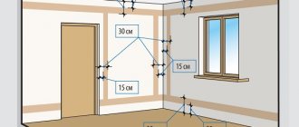
You have become acquainted with the various types of television over-the-air antennas. You can independently choose the antenna that best suits your conditions for receiving a television signal. All that remains is to install the antenna and you need to do it correctly, since otherwise all your efforts may be in vain. The antenna installation process will include several points:
1. Antenna assembly.
Antenna assembly.
When purchasing an over-the-air antenna, you will receive the manufacturer's instructions, which describe the assembly process, connecting the antenna and installing the antenna. Typically, antenna assembly does not cause any problems. But let's pay attention to some points. Many antennas are made using plastic elements; these elements can be attached either using latches or screw connections. Therefore, you should assemble carefully so as not to break the plastic fasteners or crush the fastener due to over-tightening the threads. If there are exposed contact connections on the antenna, seal them with caulk or play dough (I usually use automotive grade play dough). Carefully inspect all fastening connections. If the antenna is active (with a television signal amplifier), you need to check the quality of the amplifier connection . If there is any damage or poor quality of assembly, if necessary, eliminate any deficiencies noticed, this will help you avoid problems during further operation.
On some active antennas, amplifiers are not installed directly by the manufacturer, so we install it ourselves. For example, such antennas are common-mode antennas, popularly known as the “ Polish antenna ”, “ Grid antenna ”. The antennas are equipped with an SWA amplifier of various modifications. The process of installing the SWA amplifier itself is incredibly simple, but I have repeatedly encountered (when calling a client who tried to install the antenna on his own and failed in this seemingly simple task) the incorrect installation of such amplifiers.
Antenna connection
The photo shows an option when the amplifier is installed correctly, and an option when it is incorrect
Wrong Correct
The amplifier has contact pads to which the antenna waveguides are connected. If the amplifier is installed incorrectly, its input remains unconnected; naturally, the signal from the antenna does not reach the amplifier input, and the antenna does not work . You can spend time installing the antenna, but the result will be negative, you will have to redo the work, and you may need to replace the amplifier, since very often, if connected incorrectly, SWA amplifiers fail. We will assume that the antenna assembly has been completed and everything has been done correctly.
About the Angle Design Plug
Judging by the reviews, there are times when there is a need to move the TV with the antenna plug already inserted closer to the wall, which is problematic. In such a situation, a special plug with an angled design will help out.
You can buy it at an electrical appliance store. To connect this product, the technology described above is applicable. If the TV owner does not want to use a plug connection, then soldering will be the optimal connection method. However, for a high-quality signal, the soldered area should be smaller.
In addition, if you need to quickly connect the TV, this will be problematic. In this regard, the plug connection is considered the most convenient.
Antenna cable connection
When describing methods for connecting an antenna cable, I take examples of connecting antennas that are mass-produced. For various small-scale and homemade antennas, connections may be completely different.
There are mainly two connection methods used to connect the antenna cable.
2. Special F connector.
Let's consider both connections.
Clamped.
This type of connection is found on antennas where an SWA amplifier is used. The cable in “Delta” antennas manufactured in St. Petersburg and Rostov-on-Don is connected to the clamp. Therefore, let's consider this connection method using these antennas as an example. On antennas from other manufacturers, the clamp connection will be little different.
Clamp connection with spaced contacts.
This connection is typical for the Delta antenna.
To connect the cable, you need to remove the top layer of insulation from it.
Under the insulation is the cable braid and foil. The foil must be removed and the braid twisted into a flagellum. If the cable is of high quality and the braid is made of copper, tin the cable with tin solder to make it easier to crimp it with a contact clamp when connecting. The central core of the cable can be crimped with a contact clamp without modification. If you are “friendly” with a soldering iron, I advise you to additionally solder the cable braid and the central core to the contact clamps, this will be more reliable.
If the cable braid is made of steel, there is no need to tin it; for ease of connection, crimp it with a sleeve for a stranded electrical wire.
SWA type terminals .
Personally, I like this method of connecting the cable much more than the previous one. There is no need to worry about maintaining polarity; with this connection it is impossible to make a mistake. The cable is securely crimped with a fastening bracket, which gives additional strength to the mechanical connection of the cable to the antenna. The photo shows how to prepare the cable for connection to SWA type clamps. I would like to draw your attention to connecting the braid. The contact pad to which the cable braid is connected is located under the mounting bracket; the bracket itself is not a contact, and therefore it is necessary to ensure a reliable connection between the cable braid and the amplifier. Also, when connecting, you need to make sure that there is no short circuit between the braiding and the central core of the cable, since their contact clamps are located very close.
Connection with a special F connector.
The most convenient way to connect an antenna cable. Reversing the polarity or connecting incorrectly requires effort. The main thing is to prepare the cable correctly. The photo shows how to do this. It is necessary to remove the top layer of insulation.
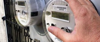
Connecting the antenna power supply
for an active antenna or a plug for a passive one (for an active antenna powered by a digital receiver, see details here ). The antenna plug is simple in design and I will not consider it; we will consider connecting a special antenna power supply. For all types of active antennas, in which the amplifier is located on the antenna itself, exactly the same power supplies are used. Before installing the antenna, I strongly recommend checking that all connections are connected correctly. Make sure the amplifier and power supply are working. To do this, you need to plug in the power supply. The control LED on the power supply case indicates that everything is fine, there is no short circuit in the cable connection, otherwise you will have to check your operation. If you plan to install the antenna on a high mast, check the functionality of the amplifier. Try to tune in to the television channel before installing the antenna; if the signal passes through, even with fading, this indicates that the amplifier is working. To be sure of this, you need to turn off the power supply from the outlet; the television signal should disappear and when you turn on the power supply, it should appear again.
Installing the antenna on a wall bracket or mast.
After assembling and checking the functionality of the antenna, all that remains is to fix it on a bracket or install it on an antenna mast; the antenna is adjusted to the maximum signal level. Installing an antenna is a responsible job, especially when the antenna is installed on a mast. Always try to complete the job safely for yourself and others. Consider all options for attaching the mast and guy wires. I will not describe in detail how to install the antenna on a mast or bracket, since there are too many options for one article.
I will pay special attention to this issue - “Grounding a television antenna.” The television antenna must be grounded. Each commercially produced antenna has a special clamp for grounding.
Why do you need to ground the antenna? There is only one answer: for a thunderstorm - safety. Of course, if lightning strikes an antenna, there is no guarantee that grounding the antenna will save your property. I personally saw what was left of the TV after a lightning discharge hit its antenna, which was installed on a steel mast. The charge passed through the antenna cable, literally turning it into a thin sintered cord. It pierced the body of the TV, incinerating the radio components in it and passing through the bedside table, went into the floor. Not a single living creature was harmed. Of course, most of the discharge energy was absorbed by the antenna and the metal mast, through which all the energy went into the ground. It is unknown what would have happened if the antenna was mounted on a wooden pole and had no grounding. Another important function of antenna grounding is electromagnetic pulse protection. A television signal amplifier installed directly on the antenna may fail during a thunderstorm, even if the storm front goes sideways. Very powerful electromagnetic pulses from lightning discharges damage the semiconductor radio components of the antenna amplifier. In this case, grounding the antenna is very effective. If the antenna is installed on a wooden pole, be sure to ground it with any wire (copper, steel, aluminum). It is not necessary to arrange a thorough grounding by burying metal strips in the ground or arranging a grounding loop. It is enough to drive a metal pin about 70 cm into the ground. This is quite enough to protect against electromagnetic pulses, and will save you from the need to dismantle the antenna and replace the amplifier.
If you have any questions, ask them here.
When connecting the plug to the antenna or connecting the cable yourself, you must follow some rules. This article is about how to correctly connect an antenna cable to a plug without errors.
F-connector "male"
FAQ
Question No. 1. Is the F-plug suitable for digital TV signal transmission, or only for analogue?
Despite the fact that this type of plug has been used for quite a long time, both its connector and characteristics allow you to fully enjoy not only analog (by the way, broadcasting will cease forever in the near future) television, but also digital and satellite television signals.
Question No. 2. What to do and what to do if the diameter of the cable is slightly smaller than the diameter of the internal thread of the plug? After all, in this case, reliable compression will not work.
In this case, it is recommended to screw the required number of layers of electrical tape onto the cable in order to adjust the diameter of the cable close to the inner diameter of the plug.
Question No. 3. When installing the plug into the corresponding socket, the TV cannot be placed close to the wall. What is the way out of this situation?
In this case, you should use an angled plug, which can be purchased at almost any store that sells electrical household appliances.
Question No. 4. In old Soviet-made TVs, the cable was connected to the plug by soldering. How to connect a modern type of cable to it?
If the signal quality deteriorates or the cable needs to be replaced due to poor contact, the plug and cable can be connected, as before, by soldering.
Question No. 5. How can you connect several TVs to an antenna or cable television network at once?
To connect several television receivers, you can use a special device - a splitter, also called a “divider” or “splitter”.
Using splitters to connect several TVs to one TV cable
Connection errors
I’ll probably start by citing the most common mistakes when connecting a cable. When installing the plug, you must immediately pay attention to this in order to eliminate troubleshooting in the future.
- The inner side of the foil does not conduct electric current; it is the base on which aluminum is sprayed. When you wrap it over the braid, there will be no contact with the F-connector. Therefore, it is better to remove it or turn it back.
- When wrapping the braid, you should pay attention that all the cores of the braid are removed and cannot touch the central core, as this leads to a short circuit. In this case, if the set-top box does not have protection against short circuits in the cable, this may lead to its failure.
- When crimping some types of plugs, you should not do this too much as this can also lead to a short circuit between the central core and the screen (braid).
Extending the cable using a splitter
This device is designed to distribute the input signal evenly. Accordingly, it has one incoming connector (labeled with the word “IN”) and several output connectors (labeled with “OUT”). Using a splitter, you can not only extend the cable, but also route it to two or three TVs at once.
The inlet hole on the splitter itself is similar in principle to the F-socket. Fixation occurs due to a threaded connection. The process of extending the cable is similar to that described for F-connectors, so there is no point in dwelling on it separately.
Connecting the antenna to the TV
To properly connect the antenna to the TV, it is better to use special plugs. Currently, so-called F-connectors (or F-connectors) have become widespread. They are installed directly on a coaxial cable with a diameter of 6.8 mm with a characteristic impedance of 75 Ohms intended for television equipment.
With this type of connector, additional attachments can be used: male and female plugs, angled plugs, cable connectors. The variety of such antenna adapters for TV is very large. The advantage of this connection is obvious; it makes it possible to connect a cable without soldering using one knife in a few minutes anywhere. This ensures the reliability of the connection against mechanical stress.
Rusty cable connection contacts
Unfortunately, there are enough counterfeits on the market and you can buy copies like these. This means that the connector was exposed to a damp environment and simply rusted. Most likely the insides of such a connector are made of iron rather than bronze or brass. In this case, signal jumps, insufficient signal levels, or even loss will be observed.
Of course, you can connect an antenna to a TV without a plug; just make contact between the RF connector of the TV and the cable. The braid is connected to the connector body and the central core must fit into the central part. Of course, such a connection is not reliable and it is better to solder it, but there is a possibility of damaging the RF contact of the TV.
Steps
Antenna connection
Determine how to connect the antenna to your TV.
It will probably be what is called
an F connector
, or a round connector with a thread and a small hole at the end. There are older types of connectors, such as the Belling Lee connector or flat connectors, but for a digital signal it is best to use the F connector.
Please note: If you have an old type connector, go to a radio parts store or a store that sells TVs and buy the appropriate adapter. Digital TVs have a special input for receiving a digital signal, usually labeled "DTV" or "DTT"
It is not possible to directly connect older types of connectors to them.
Connect the antenna to your TV using a coaxial RF cable (also known as an "F" cable). There are two main types: screw plug and regular plug. Both options are good, but a screw connection is still more reliable.
Set up your TV.
Using your TV's settings menu (read the operating instructions for specific steps), set the signal reception to "From Antenna" or "Over the Air."
Some TVs have multiple inputs: make sure you use the correct input during setup. If you have cable TV and multiple inputs, you can use one for cable and the other for antenna.
Adjust the antenna.
Scan all TV channels to see which channels are in the receiving range. If you see a unclear picture, rotate the antenna until the signal becomes clear.
Please note: Some antennas are motorized, eliminating the need to climb onto the roof to adjust the antenna. Digital TVs may have special menu options for Full Scan and Manual Scan. To optimize your antenna position, you should perform a full scan every time you change its position.
Each time, write down all the settings, do a full scan and count the number of channels found.
Identify all broadcast sources.
Find each channel's broadcast source (distance and angle) using the corresponding map of your area. If all channels are transmitted from the same direction (within 20 degrees), then it is better to use a directional antenna.
- If you need different settings to receive different signals, then write down not only the number of channels received after scanning, but also which channels.
- Determine the basic parameters you need and write them down.
- To add all channels to your TV's menu, do a manual scan after each setup and point the antenna appropriately for each channel you watch.
- Some TVs remember channels that are received well enough for a clear picture. You can use this when searching for broadcast sources.
- You can buy a better antenna that is installed outdoors. You can also purchase a controllable motor that will rotate the antenna to the optimal position to receive each channel.
- If you need to run cable, make sure you use double-shielded coaxial cable, with two layers of foil and two layers of braid around the dielectric (these are the cable parts). This will give you a better quality signal and reduce interference - which means a better received picture!
- Cable TV companies also use RF cable to transmit their channels. You can buy a simple switch to connect your cable TV and antenna to the same input at the same time.
- In the USA, on the FCC website you can find station signal reception maps for most American cities, as well as the range of signals.
- The VCR also has an RF connector on the back, usually even two. If you want to have your VCR plugged in, connect the RF antenna to the Input
to send the signal directly to the VCR. The VCR also has a built-in tuner for selecting channels and a mini transmitter called a modulator. It outputs a low-power radio signal to the output of the VCR. - You can configure this modulator to transmit different channels. The signal will go through the RF cable connected to the Output
and go to the tuner of your TV. - Tune to the channel you have selected for transmission in the modulator. Leave your TV tuned to this channel and use the VCR remote control to select channels.
Connecting the cable to the plug
F - male connector
In order to immediately correctly connect the antenna cable to the plug without any modifications, it is enough to follow certain dimensions and sequence of actions, but do not be afraid that you may get an electric shock, since the voltage in the cable is very low. So, to properly strip the TV cable you need:
- at a distance of 12 - 15 mm, make an incision in the outer shell so as not to damage the braid and, tilting it to the sides, break it off and pull it off (you can do this in a way convenient for you);
- wrap the braid;
- when folding the foil, keep in mind that its inner layer does not conduct current, so turn it around the axis again with the outer layer up or remove it altogether;
- cut the dielectric of the central core at a distance of 8 -10 mm from the end and remove it;
- screw the F connector onto the cable;
- screw the plug into the connector.
If the central core protrudes more than 4 mm, it may rest inside the connector and prevent the nut from screwing in completely, so remove the excess.
If the cable diameter is small, you can wrap a little electrical tape and then wrap the braid on it.
Crimp plug
In this case, the central core is clamped with a screw, and the braid is crimped by the plug body:
- a protective casing is put on the cable;
- the outer shell is stripped to 10 mm;
- aluminum foil is removed;
- the insulation of the central core is removed by 3 mm;
- the braid is wound onto the remaining dielectric;
- the central core is inserted into the groove and clamped with a screw;
- the braid is crimped onto the plug body;
- We screw the protective casing onto the body.
Connecting the antenna power supply separator
In this case, when connecting the cable to the power supply, the dimensions change slightly:
Correctly connect the power supply to the antenna
- the outer protective shell is stripped to 15 mm;
- the foil is removed;
- the braid moves towards the protective sheath;
- the dielectric of the central core is removed by 5 mm;
- the cable fastening screws in the separator are loosened;
- The cable is inserted into the resulting openings and clamped with screws.
Be careful when clamping the braid: firstly, it must touch the tinned area on the board; secondly, make sure that the braid does not touch the central core.
To watch over-the-air TV channels, in addition to choosing a suitable antenna, you need to connect it correctly. Let's figure out how to do this correctly, what to pay special attention to, and how to avoid possible problems that you might not have guessed about.
Connecting the F-plug to a TV cable from an over-the-air antenna or cable TV
To carefully cut a television cable, you need to cut a few centimeters of the outer sheath. The cut is made along the cable by lightly and smoothly pressing the knife. This accuracy eliminates the possibility of damage to the shielding braid.
After making the cut, you need to bend and cut off the shell (from the very beginning of the cut).
Next, the aluminum foil and copper braid are folded back. There are three options for screens used in cables. The first option is copper braid, the second is aluminum foil, the third is aluminum foil covered with copper braid (the option under consideration).
To ensure higher strength, the inside of the foil is coated with special polyethylene. This fact is not known to everyone. At the same time, cleaning plastic is an impossible task . Therefore, when the plug is wound onto the foil from the inside, the contact is very poor quality or absent altogether. To avoid this effect, you need to turn part of the foil inside out. This will allow the conductive part to be located on the outside. If the size of the internal thread F of the plug exceeds the diameter of the cable itself, it is necessary to wrap electrical tape around the cable before bending the foil. This will give the television cable the required diameter. Subsequent actions must be performed according to the recommendations given. How to properly remove insulation from the central core is described in detail in the article “Preparing wires for installation.”
Next, “winding onto the cable” is carried out, i.e. The F plug is pressed onto the foil.
The central core needs to be cut so that a couple of millimeters of the cable still protrudes.
Then the second part of the F-plug is screwed on, after which the latter is completely ready for use.
Sometimes, when installing a plug into a socket, it becomes necessary to bend the TV cable excessively, since it interferes with placing or hanging the TV close to the wall. An excellent solution to this problem is to use an angled F-plug.
The main feature of this type of design lies solely in the form. The installation processes for a traditional straight plug and an angled plug are completely identical.
Connecting a TV cable to a plastic plug of an old design without soldering
The predecessors of modern F-plugs are slightly different devices installed without soldering. They have their own installation features.
Before installing such a plug, you will need to unscrew the plastic housing. To do this, the cable must be held by the metal part, and rotation must be made counterclockwise. Then the housing is put on the cable, which will allow you not to forget about it.
Next comes the preparation of the cable for installation. It consists of making a cut in the outer shell. The size of the cut is about 1 cm. Then the sheath is removed, the shielding braid is trimmed by approximately half a centimeter, and the same amount of insulation from the central core must be removed. After completing these steps, the cable can be embedded into the plug.
The main stage is terminating the television cable. It is very important to prevent the braided conductors from touching the fasteners of the main core. The petals of the plug around the shielding winding are crimped with pliers. It is important not to overdo it - do not apply too much force, a gentle pressure is enough to ensure good contact.
Tightening the mounting screw. Screwing is carried out until it stops.
The final stage is screwing the plastic part onto the metal plug part, after which the device is ready to be inserted into the television socket.
Soldering a TV cable to an antenna plug from the times of the USSR
Today, plugs from the times of the USSR have lost their relevance and are practically not found, however, a large number of television receivers are adapted specifically to them. There are situations when the plug needs to be re-soldered.
This kind of plug was tinned according to GOST. The requirements of this document assume that tinned contacts can be soldered for at least six months, which is quite short. In most cases, after a year and a half it is very difficult to solder to the conclusions. Attempts end with the material rolling up and the plug itself turning black. To ensure a good result, the part to be soldered must be thoroughly “sanded” until a brass shine is formed. This can be done in two stages: the end of the central contact is cleaned with a flat needle file, and the contact hole itself is processed with the tip of the file (with the maximum possible rotation). At the next stage, the terminals for soldering the cable screen are cleaned, which can be done with sandpaper or the same file. Next, the terminals need to be tinned .
Then you need to prepare the ends of the cable. First, the plastic part of the plug is put on. After this, you will need to cut and remove the outer shell (2-3 cm). How to do this has already been discussed. The shielding braid is unraveled and then divided in two, the conductors are twisted. The insulation is removed from the core , but we must not forget that 2-3 mm should remain.
Threading the cable into the plug should be preceded by shortening its central core by a couple of millimeters, which will make it easier to thread the shielding conductors. The petals are slightly bent on the sides, after which the shielding wires are threaded all the way into the holes of the contact petals, and the central core is accordingly threaded into the central plug contact. At the end, the petals are pressed around the cable.
In places where the shielding wires pass through the holes of the petals, soldering is carried out. The layer of soldered material must be small, otherwise serious problems may arise with putting on the plastic plug sleeve. If the solder layer is very large, it can be removed with a file or sandpaper. There is no need to bite off the excess braid.
To remove a large load on the main core in a situation where the cable is pulled out of the TV not by the plug, but directly by the cable, you need to perform the following action. Before soldering the central core, you must pull the cable firmly, while holding the plug by the metal part. Then the core is soldered from the outside, after which it is bitten off. If “hanging” solder has formed, it must be removed with a knife. If the knife is powerless, a needle file is used.
At the last stage, it is checked how well the fixing element is bent. If it is enough, then a plastic cartridge is placed on the metal part of the antenna plug (until the latch is completely latched).
Connecting a TV cable without a plug to the TV
There are quite common cases when you need to quickly connect an antenna cable to a television receiver, but you don’t have a soldering iron or the necessary plug. But not everyone knows that the cable can be temporarily connected even without a plug. First, about 5 centimeters of the outer shell is removed, the braid is turned away and developed. Next, the insulation is removed from the central core, and the latter is wrapped in a loop. The width of the loop must exceed the diameter of the hole, which is located in the center of the socket.
For the connector shown in the photo, an insulating tube must be placed on the central contact. Then the loop is installed in the central contact, the shielding braid is inserted into the connector with the tip of a screwdriver. It is important to avoid touching the braid and the central core. The aluminum braid can be inserted into the connector, and the remaining space can be filled with small copper wires. To fix them in the connector, it is recommended to use pointed matches or simply toothpicks. This simple method of fastening is distinguished by its high efficiency and durability.
Connecting an antenna cable without a plug to a divider
In this case, the preparation process for the antenna cable is completely identical to the preparation process in the case of using an F-plug. First, the main core is inserted into the F-connector of the crab. The shielding elements are put on the part of the crab connector that protrudes. Fixation is carried out using a special clamp or simple wire. You can also use the option of fixing with insulating tape. This option is less preferable, but its performance has also been proven over the years.
When using clamps equipped with a screw-type crimping device, the connection performance is very high and is not inferior to the F-connector.
Which TV plug is better and more reliable?
Here we can safely say that the F-plug is the optimal one among the 3 connectors discussed above for coaxial cable. This conclusion can be reached by analyzing the above photos. Moreover, for this you do not need to have much experience in this field.
Here you can see that outdated and “Soviet” plugs require a small section of the central core, which is not protected by braiding. This feature does not guarantee uniformity of wave impedance, and this may cause small signal losses.
The F-plug does not have such sections. In addition, the indisputable advantage of this device is its ease of installation. It can be produced without experience, special knowledge and using a small amount of ordinary tools. This process is possible for everyone.
How to crash into a cable or terrestrial TV signal line at the entrance of a house
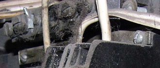
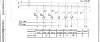
Most often, the cable is laid along the roof of the building, then, in order to increase the signal level, it is equipped with a special amplifier, after which it is routed through the entrances. Since there are several packages of TV channels, at the entrance the cable is specially branched through a filter - a crab, equipped with two outputs (an unchanged signal comes out from one, and a high-frequency cut signal comes out from the other). This principle makes it possible to prevent subscribers who have not paid for a specific package from viewing certain TV channels. This is evidenced by two identical cables running along the entrance.
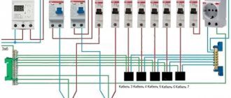
In addition, residents can see a special metal box in the entrance. Wires go out from it to each apartment. Today, new multi-apartment buildings do not use this type of structure. The wires are located in cabinets located in the walls. This is where the subscriber splitters are located. When you open the cabinet doors, you can see a similar picture. On the left in the photo is a splitter for residents - owners of an extended TV program package, on the right - for residents - owners of a simple (reduced) package.
According to the requirements, splitters must be securely fixed and grounded, but television company workers often neglect this rule. At the same time, such an attitude, oddly enough, may be more preferable. Because poor grounding often causes interference.
The design of splitters in junction boxes is identical to traditional crabs, which are used when connecting two or three TVs in one apartment, but their operating principle has a number of features. One F connector is designed to connect the cable that comes from the IN trunk. The other OUT carries the signal to the subsequent coupler, which is mounted on the ground floor. Other F TAP connectors, the number of which varies between 1-5, are needed to connect subscriber cables that go to each apartment.
The basic rule is that there are no unconnected connectors. When a subscriber disconnects (for example, in the absence of payment for services), it is allowed to use the F connector with a load of 75 Ohms as a plug. If it is necessary to connect a new subscriber, the two-socket coupler, as in the example under consideration, must be replaced with a three-socket one.
Therefore, to connect a TV, a piece of cable of the required length, at the ends of which there are F connectors, is enough. The F connector of the cable is connected to the subscriber splitter, the second connector is connected directly to the TV.
Crab and TV signal coupler - differences
The received signal power in the crab is often divided equally among the connected television receivers. The situation with the coupler is a little different. In this device, only a small part of the incoming power is allocated (about 6 dB). To guarantee the required signal level that is delivered to the user, the input signal is transmitted using an amplifier. The power of the latter is determined by the number of subscribers. As a result, the splitters used in the entrance are an ordinary crab, which has many branches.
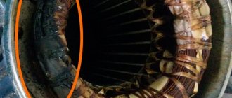
Installing a TV signal amplifier
If the signal quality is unsatisfactory, it is necessary to use a special amplifier, which is mounted in front of the crab. Its structure is similar to a regular crab, the difference lies in the presence of special active modules (microcircuit or transistors) that are capable of qualitatively improving the signal. When working with a TV amplifier, mains voltage must be supplied. This nuance must be taken into account when determining the installation location of the device. It is recommended to mount the amplifier as close to the source as possible, since this device, in addition to the signal itself, also amplifies third-party noise.
The photo shows the TERRA HA123 amplifier, which is used in home telecommunications networks. It has one output and allows gain control within the range of 8 - 28 dB. The best option is to locate the amplifier directly in the coupler box.
If the distance between the receiver and the amplifier is short, it is recommended to mount a device with multiple outputs rather than a crab amplifier. For example, the Spanish amplifier-coupler Televes 5523 with 5 outputs and a gain of 16 dB can serve 5 television receivers at once, and when installing pass-through TV sockets, much more.
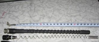
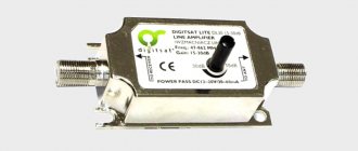
For the case when the signal comes from an individual antenna, there are a number of amplifiers used specifically for mounting directly on the antenna. Here they replace the matching loop. Such devices for amplifying a television signal guarantee high quality reception at a distance to the antenna of no more than 100 kilometers. In the photo, this kind of device SWA-555/LUX can have a different adjustment range of 10 - 15 dB (meter range), 34 - 43 dB (decimeter range) . To understand the nuances of connecting the power supply to the cable in order to supply voltage to the amplifier, you can read the article “ How to connect a television antenna amplifier to the power supply .”
The gain directly depends on the quality of the source signal and is determined individually. The voltage for these devices is supplied via a coaxial cable.
Installing a ferrite ring on the antenna cable to eliminate interference
It is not uncommon that when two or more television receivers are connected to cable TV (via cable), interference occurs on certain channels. These disturbances can be represented by black and white elements, from small dots to large waves. The reason for such phenomena is a high-frequency interference signal from a local oscillator, parallel-connected receivers, etc. Alternatively, the cause of interference may be neighboring receivers. Interference can dramatically reduce picture quality. It is recommended to solve this problem by installing a ferrite ring.
The result of using such a ring depends directly on its cross-sectional area. The put-on ring forms a choke, and together with the linear capacitance creates a U-shaped high-frequency filter. The most effective elimination of interference is guaranteed by installing a pair of rings at the ends of the cable.
Ferrite filters can be easily purchased at special retail outlets. Here they are offered in two versions: one-piece construction and two-half construction. In the second case, the halves are pressed into a housing equipped with a latch and made of plastic. Unreasonable purchase costs are easy to avoid. The thickening of cylindrical cables that go from the computer system unit to various peripheral equipment are the most common ferrite filters.
If you look carefully, you are sure to find abandoned and forgotten interface cables in every home. To use them, you just need to cut the plastic with a knife and remove the ferrite ring. After this, it can be placed on the antenna cable. This will allow you to completely forget about all kinds of interference.
You need to buy cables, splitters, amplifiers and other accessories described above in specialty stores. Here, professional consultants will provide the required information and help you choose exactly what you need. However, in order to communicate on equal terms with specialists, you need to understand at least a little in this area, and you can easily obtain the necessary knowledge from the information above.
Cable selection
To connect the antenna to a TV or digital set-top box, a coaxial cable with a resistance of 75 Ohms is required. There are many brands from different manufacturers on the market. Which to choose?
Start with the core type.
To transmit a TV signal from an antenna to a TV receiver, cables are used in which the central core is made:
- Made from pure copper. Used for satellite television systems: the signal transmitted from space has extremely low power, and any losses are inappropriate here. Copper has very low resistance.
- With copper plating. The central core is steel, but covered on top with a thin layer of copper. Such cables are used for terrestrial television systems: signal loss is greater, but not critical, and copper-plated steel costs almost 2 times less.
When choosing a cable, it is important to consider:
- Type of signal being transmitted. “Brand” brands of cables are best used for satellite TV antennas. For broadcasting or cable wiring, simple domestic ones are sufficient.
- Length of the route. Even “premium” brands have internal resistance, and the longer the signal path, the greater the loss. At distances up to 5 m, this can be neglected, but when connecting an external antenna on a high mast, the distance will affect it.
- The thickness of the central core. Standard cables have a core 1 mm thick. There are also thinner cords with a half-millimeter core. They are more convenient to install, but they are more difficult to connect to devices, and resistance losses are often higher.
- Possible obstacles on the installation path. If there are sources of interference nearby (alarm lines, electrical wiring, etc.), it is better to buy an option with maximum shielding.
- Outer shell material. The cable is insulated from the outside using black PVC or white polyethylene. The difference indoors is small, but for outdoor work craftsmen recommend more reliable PVC.
Among the brands of cables used for television antennas, the most popular are the following:
- RG 6. Product of joint Russian-Chinese production. Inexpensive, but high-quality, shielded, with a 1 mm central core made of steel or copper, aluminum braid and PVC sheath.
- RK 75. A purely Russian analogue of RG 6, produced since Soviet times. It has a copper central core with a diameter of 1 mm, a copper braid or a double screen made of tinned copper and aluminum lavsan. Can be used both for broadcasting terrestrial or cable TV, and for connecting satellite antennas (with a double screen).
- RG 59. Thin and light cable with a 0.5 mm core. It is universal, but due to the high resistance of the wires it is unsuitable for transmitting a signal over a distance of more than 200 m.
- SAT 50. Italian, with a millimeter core and a two-layer reinforced braid of copper and tin. It has a high shielding coefficient - up to 60 dB.
Is it possible to connect a television cable with your own hands without losing quality?
To correctly connect a telecommunications wire with a coaxial cord, you should use one of the following methods:
- Purchase a standard extension cord of standard length, with which you can increase the length of the antenna cable to 20 meters;
- Use special F-sockets that allow you to connect antenna wires without soldering;
- Modern technologies make it possible to extend several wires simultaneously using splitters;
- Solder the wires together to create an unbreakable connection.
Connecting the Antenna Wire
Also, special care should be taken to select the correct coaxial cord since the antenna wire has a resistance of 75 ohms. The outer braid must have extreme elasticity, since this property will allow it not to break at the bends
In addition, to avoid loss of image quality, it is necessary to purchase products that have a dense internal braid to guarantee the reception of a stable continuous signal.
Note! The dielectric, which acts as an insulator, must be made of polyethylene and foil to prevent signal failure due to external interference during operation. The cable core can be made of copper, aluminum or steel
The frequency signal settings should be low.
Cable connection without network loss
Antenna plug selection
When you have selected the desired option, connect the antenna cable correctly. You can do this in the following ways:
- Soldering. Only suitable for installing homemade TV antennas. We don't recommend it.
- F-plug. Suitable for connecting antennas for both digital and analogue television. Structurally, it is a washer that is screwed onto the end of the cable, where the outer insulation has been stripped and the braid and screen have been bent. The plug crimps the bent shielding elements, and the exposed central core is connected to the signal slot. We recommend!
- Old style plug. They were produced back in Soviet times. It differs from the F-plug in that it requires complete disassembly for installation. It has greater rigidity, and when assembled correctly, the strength is higher than modern ones. It is permissible to use.
Wire connection methods
Some people turn to specialized workshops to install a TV antenna, but most home craftsmen prefer to do this work themselves. It is not particularly difficult and can be done by anyone who has basic knowledge of electricity and understands how to select and install an antenna cable for a TV.
There are several ways to connect antenna wires to each other:
- Soldering (using a soldering iron with tin and rosin).
- Twisting (mechanical twisting of the free ends of the wire).
- F-nut connection (simple and securely fixed threaded contact).
Due to the complexity of the first two options, we will consider the most current, easily accessible and time-tested method of connecting a cable using a special connector - an F-nut. Although there are two more ways to solve the problem, they require much more time and effort, without guaranteeing one hundred percent success in terms of high-quality signal reception. The first method additionally requires skills in handling a soldering iron.
Stages of work completion
Before starting work , you should disconnect the television receiver from the power supply. Then you need to carefully inspect and feel the antenna wire for wear on its outer insulation. If there are microcracks and peeling in certain areas, it is advisable to completely renew them. After this, you need to measure the length of the TV cable that requires replacement or extension and write down the indicators. A large number of docking nodes is extremely undesirable, since each of them affects the quality of the received signal. The best option is to replace a single piece of antenna wire from the divider to the TV.
When extending the cable, it is better to create a reserve of its length for a possible change in the location of the television receiver in the future, and roll the excess into a ring of small diameter and secure it by wrapping it with adhesive tape.
Before going to buy materials for an antenna, it is advisable to cut off a small piece of the existing wire as a visual example for selecting a similar one. This will help you choose the right cable if you don’t know its letter or number designations.
Antenna cable assembly
The F-plug is mounted on the cable as follows:
- Take the connecting end and carefully remove it from the outer insulation at a distance of about 1 cm from the edge.
- Carefully wrap the exposed braid and foil screen back onto the part of the cable where the outer sheath is still intact.
- Cut and remove the freed portion of the inner insulation to expose the center core.
- Screw the F-plug onto the wrapped braid.
- Cut the central core with wire cutters so that about 2–3 mm of wire remains sticking out.
- Screw the second part, the adapter, onto the half of the plug that has already been put on the cable until it stops. This is not a required component, but using a “dual-layer” plug improves contact between the wire and the equipment.
If you need to connect an old-style plug to a cable, the process depends on its design.
But most often it looks like this:
- Disassemble the plug by unscrewing the metal contact from the plastic housing.
- Immediately put the unscrewed housing on the cable - this makes it easier to continue working.
- Cut off about 1 cm of the outer sheath of the wire, remove the insulation.
- Carefully trim the shielding braid by 4–5 mm.
- At the place where the braid was cut, carefully strip off the inner insulation so that the central core is exposed.
- Insert the central core into the socket of the metal part of the plug. Using pliers, gently but firmly squeeze the petals around the exposed shielding shell. Here you need to make sure that the braid does not touch the central core.
- Screw in the center core fixing screw.
- Screw the plastic shell onto the metal part. The plug is ready.
Another option is soldering. The process is shown in the photographs.
The described procedures relate to preparing the cable for the antenna socket of the TV receiver. However, if the TV is connected via a set-top box, the procedure for installing the plug will be identical.
Overview of species
Let's take a closer look at the overview of the main types of television plugs.
Wrapped
This model with an amplifier in the form of a pressed-on nut has become quite widely used among modern users. Its popularity is very easy to explain - connecting such a plug is very simple. At the same time, connectors of this type also have their disadvantages:
- insufficient thickness of the crimp ring often causes damage to the plug during installation;
- shortened internal thread, which does not allow the wire to be fixed tightly in the connector;
- When screwing a connector onto a cable, the braided conductors often break and the protective layer becomes twisted.
Crimping
The crimp-on F-plug for a TV is characterized by a simplified mounting method. To do this, it is necessary to prepare the cable in accordance with the basic rules, then insert the main wire into the narrow hole of the convector, thoroughly cut through the foil and winding and fix it to the outer wall using a crimping movable sleeve
We pay special attention to the fact that before clamping it is necessary to distribute the bent layer as evenly as possible along the entire circumference of the wire
Compression
These antenna connectors for television equipment are considered the most reliable in this series. However, their installation requires professional tools, as well as a specific understanding of the fastening features. The fact is that the prepared cable is inserted into the compression connector using special clamping pliers, while the crimp sleeve itself is pulled towards the functional end.
Connecting the antenna to the TV
Typically, the antenna jack is located on the back of the TV and is labeled “ANT”, “ANT IN” or similar. But the easiest way to identify this nest is visually. It is characterized by the following symptoms:
- ring-shaped metal edging;
- the central groove is a convexity with a hole into which either the central core itself or a protrusion inside the plug fits.
The antenna jack differs from other connectors in shape. It is physically impossible to connect anything other than the plug itself.
If the TV can receive both terrestrial and satellite signals of the DVB-S standard, it has two antenna connectors. The one intended for the satellite signal is marked as “ANT SAT”, “ANT 2 IN SATELLITE”, etc. The satellite antenna socket also has a notch in the center, but usually has an external thread for screwing the plug onto it.
What mistakes do newbies make?
Not everyone knows that some antenna cable manufacturers cover the inside of the foil with polyethylene. It is quite difficult to clean this material, even with a scalpel. If the cable can be stripped, the presence of plastic will become a significant obstacle to quality contact with the plug. As a result, the signal will be distorted. This can be prevented if the foil is turned back and turned back so that its conductive side comes out. Often, when crimping, thin braided wires come into contact with the main cable core, as a result of which the quality of the received signal is not at the proper level, and may even disappear completely. Often the antenna cable is laid in the same baseboard along with the electrical wiring. This, according to experts, is unacceptable, since with such installation the signal transmission will also be of poor quality.
Temporary connection of an antenna cable without a plug
If you urgently need to connect the antenna, but there is no plug at hand, you can do without it for a while.
A quick connection is done like this:
- the top insulation approximately 5 cm long is removed from the cable;
- the shielding braid is bent back;
- the central core is stripped of insulation and bent into a loop slightly wider than the diameter of the hole in the center of the antenna connector;
- a dielectric tube is put on the central contact (for example, from the removed insulation from the central core);
- the loop is inserted into the central contact, the braid is tucked into the connector using a screwdriver. The main thing here is to prevent contact between the central core and the shielding braid;
- if aluminum braiding is used, then it is simply inserted into the connector, and the free space is filled with small wires;
- to prevent the cable from falling out, it is tightened with a pair of sharpened matches;
- If contact has been achieved, the TV will begin to receive a signal from the antenna.
Elimination of TV interference
External electromagnetic influences on wire lines that arise during operation of the TV are eliminated by increasing the self-induction coefficient and using a special ferrite filter, which is used to suppress high-frequency interference in electrical networks.
The ferrite ring is a node in the electrical network of the power supply, filtering and absorbing high-frequency interference. Their impact allows you to:
- single-core wires absorb radiation, convert it into heat, heating the conductors; amplify incoming pulses by returning a portion of the high-frequency magnetic field to the insulated conductor;
- multi-core wires act as a common-mode converter, passing signals through one signal and common wire, extinguishing commensurate ones.
The need to obtain a simultaneous normal television signal for a similar mounted television requires the use of a “crab”. The separator from the antenna, common dish is used in residential multi-apartment buildings, places of temporary residence, and sports facilities. The power of the incoming television signal is divided into equal shares between all connected devices.
A correctly mounted “crab” retains the necessary power and ensures high-quality digital and audio transmission of signals during long-term operation of the television unit.
Connecting the cable to an individual antenna
Depending on the connection method, individual antennas are of two types:
- The cable and plug are attached by the manufacturer. As a rule, these are indoor antennas with a short wire length;
- You must connect the cable yourself.
In the latter case, the procedure looks like this:
- The top insulation is removed from the cable, the braid is wrapped back;
- the insulation is removed from the central core. Dimensions depend on the connection socket on the antenna;
- the core is inserted into the screw connection and clamped there using a screwdriver;
- the braid together with the cable is pressed against the second terminal.
Extending the cable using a splitter
This device is designed to distribute the input signal evenly. Accordingly, it has one incoming connector (labeled with the word “IN”) and several output connectors (labeled with “OUT”). Using a splitter, you can not only extend the cable, but also route it to two or three TVs at once.
The inlet hole on the splitter itself is similar in principle to the F-socket. Fixation occurs due to a threaded connection. The process of extending the cable is similar to that described for F-connectors, so there is no point in dwelling on it separately.
How to connect several TVs to 1 antenna
If you need to connect several TV receivers to one antenna, you will need cable routing devices - splitters or splitters. In the simplest case, the connection will look like this:
- The coaxial cable coming from the antenna is stripped, an F-plug is put on it, and it is connected to the input jack of the splitter.
- Wires for TVs are prepared and inserted into the output sockets using connectors.
If the signal is taken from an active antenna, you need a splitter with a power pass or connecting an external power supply antenna amplifier in front of the splitter.
Depending on the model, splitters can have from 2 to 8 outputs. If more TVs are connected, you need to calculate and build a chain of new splitters and signal amplifiers.
How to extend a TV cable?
Radio mechanics identify the following options for connecting and extending the antenna cable:
- F-connectors are a special metal structure that allows you to reliably connect two pieces of cable without the use of a soldering iron or additional insulation. The method is often used when, when moving the TV to the other end of the room, the available supply of cable is not enough or the damaged section needs to be replaced. This is the simplest and most economical method, as opposed to laying a new cable directly from the antenna.
Next, we will look at the practical application of each described method of connecting an antenna cable.
With the transition of analogue broadcasting to digital form, the requirement of televisions for the broadcast signal has increased. Residents of suburbs and villages now use TV tuners with amplifiers. Therefore, the quality of the connection of television wires came to the fore.
Antenna amplifier: in what cases is it needed?
In order for the digital tuner of a TV or receiver to extract information from the signal received from the antenna, it must have sufficient power.
To correct this situation, you just need an amplifier. The device is connected in the area between the antenna and the TV and increases the signal strength.
An amplifier is needed in the following situations:
- reception is carried out using a passive antenna;
- it is not possible to use power from an active antenna (for example, the signal to TVs goes through a regular splitter);
- The reception conditions are such that the signal received from the antenna is too weak. This happens due to distance, interference, obstacles in the signal path, etc.
How to extend a TV cable?
Radio mechanics identify the following options for connecting and extending the antenna cable:
- F-connectors are a special metal structure that allows you to reliably connect two pieces of cable without the use of a soldering iron or additional insulation. The method is often used when, when moving the TV to the other end of the room, the available supply of cable is not enough or the damaged section needs to be replaced. This is the simplest and most economical method, as opposed to laying a new cable directly from the antenna.
Next, we will look at the practical application of each described method of connecting an antenna cable.
With the transition of analogue broadcasting to digital form, the requirement of televisions for the broadcast signal has increased. Residents of suburbs and villages now use TV tuners with amplifiers. Therefore, the quality of the connection of television wires came to the fore.
Selection criteria: what is important and what is not
And here and now we will look at the specifics of selecting indoor receivers, and then we will talk about the most stable and powerful models for installation inside a house or apartment.
Type of received waves
Digital TV is broadcast in the decimeter range (UHF), that is, its wavelength is less than a meter. In fact, there are no special digital antennas: DVB-T2 can be received on any installation that picks up a suitable range. Specifically for the “digital”, due to its decimeter nature, you need:
- UHF antenna. It is usually small, since the dimensions of the resonators must at least approximately correspond to the wavelength;
- All-wave (also hybrid or combined). Usually this is the same UHF antenna, but equipped with additional resonators for the UHF range. They are useless for digital, but can be useful if, in addition to it, local analog television is also transmitted from the repeater.
It makes no sense to use MV antennas, which were often used for analogue broadcasting. Even if the signal can be detected, it will be extremely weak and of poor quality.
Design
According to their design, indoor antennas are divided into the following types:
- Unidirectional. In essence, this is an indoor analogue of an external individual television antenna. Usually it looks like a pin on which “horns”-resonators are attached, although other designs are possible (for example, a wave channel). The main property of this design is the best reception from where it is oriented. Due to this, the signal is maximally amplified. Suitable for areas with a relatively weak signal.
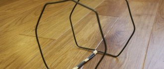
- Flat. These may look different, but in general they are usually a closed loop of appropriately sized conductor. In the simplest case, a ring of cable with a diameter of 25–30 cm. The best reception is ensured when the direction to the repeater is perpendicular to the plane. Suitable for medium power signal.
- Spherical. This rather rare design is something like a globe model made of wire: three rings perpendicular to each other. The antenna is convenient in that it receives a signal from any direction (that is, it is of the omnidirectional type) and does not require orientation. However, it needs a very powerful signal. In practice, they are rare: the peak of popularity of experiments with such a design was in the 60s and 70s, now few people dare to produce this for broadcast television. Much more often they can be found as satellites: there a ball of dielectric material acts as a lens that can simultaneously focus signals from several satellites.
Gain
Passive (no power)
Ordinary television antennas without additional electronic components are called passive. In them, under the influence of an electromagnetic wave, oscillations arise, which are transmitted for decoding to a digital TV tuner (built into the TV receiver or external in the form of a set-top box-receiver). The main advantage of such an antenna is that it does not require additional power supply for the signal amplifier.
Average gain – up to 6 dB. They are suitable where the signal from the repeater has high or medium power, and the distance to the TV tower is short.
Active (powered)
These antennas additionally have an electronic unit that amplifies the oscillation power. They can have a gain of up to 27–30 dB. It is interesting that an active type antenna can also be used as a passive one. To do this, as a rule, it is enough to simply turn off the power. The reverse process is usually impossible without serious alteration of the entire structure.
Active ones, depending on the design, can use direct current of 5 or 12V. The difference here is this:
- a 5V current is supplied through the receiver or antenna socket of the TV, if this equipment has such an option;
- 12V current is supplied from an external power supply plugged into an outlet.
An antenna with external 12V power supply is convenient in cases where it will be used for 2 or more TVs or receivers. The splitter (cable splitter) may not transmit power from the set-top box or TV receiver. In addition, many TV models with a built-in digital tuner do not support antenna power, and an external source will be required.
These are the most powerful devices; they are capable of receiving a signal at a distance of up to 40–45 km from the repeater. Therefore, they can be used outside the city, in the country, in rural areas, etc.
There are many manufacturers from different countries on the TV antenna market. And every day new brands appear. Theoretically, the brand can say something about the quality of the antenna. But you really need to focus on the technical characteristics, and not on the brand.
Connecting the cable by soldering without an adapter
The algorithm described below is suitable even for connecting wires of different designs. The method is high quality and quite simple. You just need to know how to use a soldering iron.
- Using a sharp knife, cut the shell lengthwise by 5-6 cm.
- Bend the insulation along with the shielding back.
- Cut the inner dielectric layer along with the core by 2 cm. This is done so that there is a reserve of braid when connecting. The braid of one wire will overlap the braid of the other.
- Make a cross cut about 2 cm across the central dielectric and remove the insulating material so that only half remains.
- To solder the wires, make a bend of approximately 45°. It will be more convenient to solder if you make the angle between the copper core and the dielectric about 90°.
- Tin the vein.
- Repeat the above steps from all points on the second antenna cable.
- Both wires lean against each other along the entire length.
To prevent the strands from diverging during soldering, you can wrap them with thin tinned wire. Alternatively, use braided thread after tinning it first. In order for one sheath to tuck into the other at the last stage, when the wires touch, the initial cuts must face each other. - Solder the wires. Tin should cover the vein evenly along the entire length. It is advisable not to form an extra thick layer of solder. If this has formed, or there are sharp protrusions, grind them off with sandpaper or a file.
- Align the cable so that both halves of the dielectric fit tightly. Carefully trim off excess protrusions, maintaining minimal gaps.
- For reliability, you can wrap the dielectric with electrical tape.
- Return the foil (aluminum) screen to its original position. At the junction, one layer should overlap the other by about 20 cm. But the inside of the material is not conductive. Therefore, it is necessary to unfold the approaching layer from above so that there is contact between the conductive surfaces.
- Attach the braid in the same way. Additionally, you can solder the threads.
- Thread the sheath from the first wire first. And cover the second material on top of the first shell.
- The last step is to prevent the shells from coming apart, wrap the entire connection with electrical tape.
HDMI ARC what is it
What is HDMI ARC. The HDMI in3 (ARC) audio return channel connection is standard starting from version HDMI 1.4; the HDMI cable, in addition to the video signal, also transmits an audio signal back from the TV to the speakers, so you can also output sound from the TV. All HDMI ports since version 1.4 support this feature. But there are cases when the manufacturer of HDMI chips, to reduce the cost of production, makes the audio return channel only in one port. This is common practice. But according to the rules, if the port is HDMI 1.4 or later, all ports must support ARC.
Unlike previous versions, when it was necessary to use external acoustics to output sound. The return channel will allow you to receive, for example, a signal from the air and output sound via HDMI to connected speakers, but in an uncompressed format, only stereo. The 5.1 audio format is transmitted only in a compressed format up to HDMI 2.1.