Basic Concepts
Voltmeter
Voltage drop is the value reflected in the change in potential in different parts of the conductor. The current flowing from the source towards the load changes its parameters due to the resistance of the wires, but its direction remains unchanged. You can measure the voltage using a voltmeter:
- two devices at the beginning and end of the line;
- alternate measurements in several places;
- a voltmeter connected in parallel to the cable.
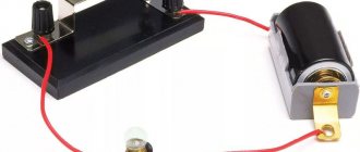
The simplest circuit is a power source, conductor, load. An example would be an incandescent lamp plugged into a 220 V socket. If you measure the voltage on the lamp with a device, it will be slightly lower. The drop occurred in the lamp resistance.
The voltage or voltage drop across a section of a circuit can be calculated using Ohm's law using the formula U = IR, where:
- U – electrical voltage (volts);
- I – current strength in the conductor (ampere);
- R – resistance of the circuit or its elements (ohms).
Knowing any two quantities, you can calculate the third. In this case, it is necessary to take into account the type of current - alternating or direct. If there are several parallel connected resistances in the circuit, the calculation becomes somewhat more complicated.
How to lower voltage using a resistor
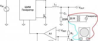
To prevent the load that needs to be powered from burning out, it is often necessary to reduce the input voltage. The easiest way to achieve this is to use a two-resistor circuit, better known as a voltage divider. The classic scheme looks like this:
In this case, the voltage is supplied to two resistors using a parallel connection, and at the output it is received from one. The selection of resistor values is carried out according to the formula so that the voltage removed at the output is some part of the supplied one. You can calculate a resistor to reduce the voltage using a formula based on Ohm's law:
Uout= (Uin*R2)/(R1+R2), where
Uin – input voltage, V;
Uout – output voltage, V
R1 – resistance index. 1st resistor (Ohm)
R2 – resistance index. 2nd element, (Ohm)
Selecting a resistor to reduce voltage
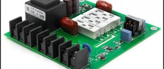
To select the required resistor resistance, you can use ready-made online calculators or programs for simulating the operation of electronic circuits. Electrical circuit simulators are capable of not only calculating the output voltage depending on the resistance of the elements and the method of their connection, but also have functionality that allows you to visualize how the current and voltage across the resistor drops. For example, the EveryCircuit application allows you to change the parameters of elements in the circuit, select the simulation speed, and obtain data at various points. In this case, you can observe the dynamics of changes in values using the rotating dial in the lower right corner to enter input parameters.
There are also a number of free emulation programs that allow you to perform, among other things, calculations of a resistor when the voltage drops, for example:
- EasyEDA;
- Circuit Sims;
- DcAcLab;
and others.
In the article, we became acquainted with the concept of resistance, learned about its units of measurement, the marking of resistors, programs that emulate the operation of a circuit and facilitate the selection of the desired resistance, and also looked at examples of calculating the voltage drop across a resistor.
Result of undervoltage
A common phenomenon is when the input voltage is detected below the established norm. Subsidence along the length of the cable occurs due to the passage of high current, which causes an increase in resistance. Losses also increase on long lines, which is typical for rural areas.
According to regulations, losses from the transformer to the most remote area should be no more than 9%. The result of deviation of parameters from the norm may be as follows:
- failure of energy-dependent installations and equipment, lighting devices;
- failure of electrical appliances at low input voltages;
- reduction in torque when starting an electric motor or compressor unit;
- starting current leads to overheating and shutdown of the engine;
- uneven current load at the beginning of the line and at the remote end;
- lighting fixtures operate at full intensity;
- losses of electricity, underutilization of current power.
The characteristics and operating parameters of electrical appliances are changing. For example, due to low power, the time for heating water by a boiler increases. A decrease in voltage leads to failures in the electronics.
In operating mode, voltage loss in the cable can be up to 5%. This value is acceptable for energy industry networks, since high power currents are delivered over long distances. Such lines are subject to increased requirements. Therefore, in case of household losses, attention should be paid to secondary energy distribution networks.
Ohm's Law - Power
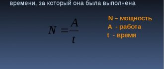
When electric current flows through a resistor, it dissipates a certain amount of power as heat.
Power is a function of the flowing current I (A) and the applied voltage V (V):
Where
- P - power in watts (V)
In combination with Ohm's law for a section of a circuit, the formula can be converted to the following form:
or
An ideal resistor dissipates all energy and stores no electrical or magnetic energy. Each resistor has a limit to the amount of power that can be dissipated without causing damage to the resistor. This power is called rated power.
Environmental conditions may lower or increase this value. For example, if the surrounding air is hot, then the resistor’s ability to dissipate excess heat decreases, and on the contrary, when the ambient temperature is low, the resistor’s dissipation ability increases.
In practice, resistors rarely have a power rating. However, most of the resistors are rated at 1/4 or 1/8 watt.
Below is a pie chart that will help you quickly determine the relationship between power, current, voltage, and resistance. For each of the four parameters, it shows how to calculate its value.
Causes of voltage drop
Phase imbalance in a three-phase circuit
First of all, you need to figure out whether it is the fault of the electricity supplier or the consumer. Network problems arise for the following reasons:
- deterioration of power lines;
- insufficient power of transformers;
- power imbalance or phase imbalance.
These problems are related to the supplier and cannot be resolved independently. To understand whether high-voltage lines are working correctly or not, you will have to call energy sales representatives. They will take measurements and draw up a conclusion.
You can make sure that the fault of the fall is not related to the supplier yourself. First of all, you should find out from your neighbors if they have similar problems. A multimeter is suitable for measuring voltage at home. Its cost is up to 1000 rubles. If the device at the entrance to the apartment shows normal voltage, the reason must be looked for in the home network.
The voltage may drop due to the long length of the wiring. When the length of the network exceeds 100 meters and the cross-section of the conductors is 16 mm, the oscillations will become regular. To correct the situation, you will have to change the wiring.
Weak contacts are additional resistance to current. It reaches devices in insufficient quantities. In addition, faulty contacts can cause a short circuit and lead to a fire. To normalize the performance, you need to replace the faulty section of the circuit and burnt contacts.
The culprit may be an incorrect connection of the wires running from the power lines to the house. Sometimes, contrary to safety requirements, copper wires are connected to aluminum or copper conductors are connected by twisting instead of terminals. The terminals and clamps are made of low-quality materials or their expiration date has expired.
Perhaps the fault lies in the input device itself. In this case, it should be replaced.
How to calculate losses
Linear relationship between voltage and current
When calculating an electrical line, voltage deviations should not exceed regulated standards. Permissible fluctuations for household single-phase networks are 209–231V; for a three-phase network, the voltage can vary from 361 to 399 V.
Fluctuations in current and power consumption lead to changes in voltage in the conductors near the consumer. Therefore, when drawing up a wiring diagram, it is necessary to take into account the allowable losses.
In a single-phase network there are two wires, so the voltage drop can be found using the following formula: U=I*R, in turn, R=(r*2i)/S.
- where r is the resistivity, which is equal to the resistance of a wire with a cross-section of 1 mm2 and a length of 1 m;
- i – designated as the length of the conductor;
- S – cable section.
AutoCad program for calculating voltage drop
In a three-phase network, the powers on the phase wires compensate each other, and the length of the neutral conductor is not taken into account, since no current flows through it. If the load across the phases is uneven, the calculation is performed as for a single-phase network. For long lines, capacitive and inductive reactance are additionally taken into account.
The fall can be calculated using an online calculator, and there are also special tables. They show the permissible current loads for different types of cables. When calculating the cable cross-section, the following data must be taken into account:
- conductor material;
- hidden or open laying of the line;
- current load;
- environmental conditions.
When current flows through a cable, wire or bus, it heats up. This process changes the physical properties of the conductors. The insulation melts, the contacts overheat, and the wire burns out. The reliability and uninterrupted operation of the electrical network depends on the correct selection of cable.
How to Reduce Voltage Drop and Cable Loss
You can reduce the amount of losses by reducing the resistance throughout the electrical network. Savings come from the method of re-grounding the zero on each power line support.
The cost of power supply with a long-distance line selected based on the permissible voltage drop is higher than the choice made based on cable heating. There is still an opportunity to reduce these costs.
- Strengthen the initial potential of the supply cable by connecting it to a separate transformer.
- You can achieve constant voltage levels in the network by installing a stabilizer near the load.
- Connection of consumers with low loads of 12–36 V is carried out through a transformer or power supply.
The longer the power line cable, the greater the resistance that occurs when current passes through it. Obviously, the voltage loss is also higher. They can be reduced by combining methods with each other.
- Reduce costs by increasing the cross-section of the power cable. But this method will require large financial investments.
- When developing power supply lines, you should choose the shortest possible path, since a straight line is always shorter than a broken line.
- As the temperature decreases, the resistance of metals decreases. Ventilated cable trays and other designs reduce line losses.
- Load reduction is possible if there are many power sources and consumers.
Savings come from proper maintenance and prevention of electrical networks - checking the density and strength of contacts, using reliable terminal blocks.
The issue of energy conservation must be approached with full responsibility. The problem of voltage loss can damage expensive devices and tools. Do not neglect safety measures; they will level out power surges and protect household appliances and equipment in the enterprise.
Voltage divider circuit using resistors
The voltage divider circuit includes an input voltage source and two resistors. Below you can see several schematic versions of the divider, but they all have the same functionality.
We recommend reading: DIY generator voltage regulator relay: diagram
Let's denote the resistor that is closer to the plus of the input voltage (Uin) as R1, and the resistor that is closer to the minus as R2. The voltage drop (Uout) across resistor R2 is the reduced voltage resulting from the use of a resistor voltage divider.