Induction electrical appliances have been used in metallurgy and welding for a long time. Despite the apparent complexity of the devices, their production is not high technology. Therefore, this principle has been widely used in everyday life for two decades: in particular, in the creation of electric stoves.
Breakdown of equipment with such a heater is not a big problem, but service centers charge impressive price tags with each call. Therefore, if you have basic radio skills, you can repair an induction cooker yourself. Our review will tell you about this.
How does an induction heater work?
The principle of operation is not based on heating metals by induced eddy currents. Any metal that comes into contact with a high-frequency magnetic field heats up intensely. To do this, several conditions must be met:
- The material must effectively absorb the energy of the vortex field. Therefore, cookware for such stoves is made of ferromagnetic metals. Most often it is steel.
- The oscillation frequency of the alternating magnetic field must be no less than 20–60 kHz; for this, appropriate generators are used.
- The area of action of the induction field is very compact, so the metal (in this case the bottom of the cookware) should be as close as possible to the inductor.
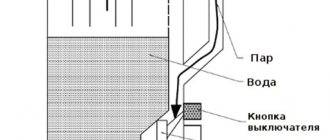
From the point of view of the physics of the process, this is a high-frequency transformer.
The role of the primary winding is performed by an inductor through which a high-frequency current flows. The secondary winding is nothing more than the bottom of the dish, in which, when exposed to an alternating magnetic field, the same currents arise as in the coil. Due to this, strong heating of the metal occurs.
Let's look at one more condition:
- The surface area of both coils (and they are structurally flat) should be as equal as possible.
Only in this case is the balance of energy transfer ensured. What is it for? In empty space (above the inductor), eddy currents operate idle. The “extra” energy of the magnetic field begins to overheat the primary coil. In addition, the excess temperature load is transferred to the output stages of the high-frequency generator. If the cooling radiators fail, the circuit fails and repairs to the induction cooker components are required.
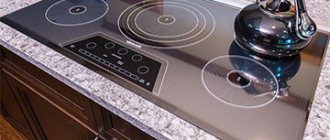
Induction heater device
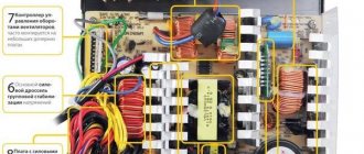
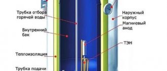
The illustration shows the main components of the heating element (conditionally without the top “winding”), that is, there is no cookware.
- A temperature sensor monitors the degree of heating and turns off the power in critical modes.
- The coil (primary winding) is a massive copper conductor tightly laid in a spiral.
- Ferrites placed in the housing form a ferromagnetic complex together with the coil.
- The printed circuit board of the high-frequency alternating current generator is equipped with an output stage heat sink, with forced cooling (fan).
- The generator housing provides effective airflow to the entire circuit.
Rules
In order for the repair to take place in compliance with all norms and regulations, it is necessary to carefully prepare for it. The electric stove is disconnected from the electrical network. De-energizing induction equipment is necessary for work safety. Many tools may be required during inspection and subsequent repairs. You need to prepare them in advance. You will need:
- a set of screwdrivers of different diameters with the necessary attachments;
- insulating tape;
- multimeter for checking individual elements of the stove;
- indicator screwdriver, which is necessary to check the voltage.
Advice
During work, you must follow the operating instructions for the induction cooker model being repaired. Many parts are located by the manufacturer from different angles. To gain access to them, you need to be well versed in technology and have an idea of the design features.
Real and imaginary malfunctions of induction cookers
- Full power is not realized. As a rule, this situation arises if the bottom of the pan is located offset from the center of the burner, or the diameter of the bottom is significantly smaller than the size of the hob.
It is possible that the burner is not tightly pressed from below to the decorative surface (the fastenings are loose, or the clamping springs have burst). If the power changes abruptly, the temperature sensor may be triggered. It is necessary to find the cause of overheating of the induction winding. The spiral may burn out or short between turns. - Some of the burners are not working. First of all, the power connection to the faulty nodes is checked. Every generator may have fuses. Also, the connecting connector from the control unit to the inductor may fail due to overheating.
- No response to touchpad. If there is grease contamination, the sensors may not “feel” your fingers. Clean the surface. If this does not help, check the connecting cables from the control panel to the inductor circuit.
- There is no display of residual heat (in fact, the temperature of the hob in operating mode). The cause may be a broken temperature sensor. If it is working (you can check it on a working burner), it should be replaced. Of course, we check the reliability of the connecting wires.
- The cooling fan is constantly running. The noise of the propeller can be heard for some time after finishing work; the induction coil does not cool down immediately. If the fan runs immediately after turning on the power (when the burner is turned off), the temperature sensor may be faulty, or the temperature in the area of the hob is above +50°C.
- The fan is not working. There are only two reasons: either the motor has burned out (we check by forcing the voltage supply), or there is a breakdown in the control circuit (temperature sensor, control module).
- Unreasonable shutdown of the hob. First, let's understand the standard reasons for shutdown:
- within 10 seconds after switching on, you do not perform any active actions;
the burners (at least one of them) operate in heating mode for more than 2 hours in a row;
- The timer shutdown may be set for a short period of time.
- The induction cooker does not “see” the cookware. First of all, check the material of the pot or pan body. There should be a corresponding designation on it (for induction cookers). As a last resort, you can check the metal using a permanent magnet. Non-magnetic materials (aluminum, copper alloys, stainless steel) are not detected by induction burners. If the dishes are in order, we check the temperature sensor and control unit again.
If the above reasons are absent, we will deal with the temperature sensors and control panel.
Helpful advice: if you don’t have suitable cookware and you only have an induction cooker, use a ferromagnetic disk of suitable diameter. These are commercially available, or you can make one from a thick steel pan.
True, the cooking efficiency will sharply decrease, because the heat source will not be the cookware itself, but the metal disk. But you can cook in your favorite copper frying pan or heat-resistant glass pan.
Important! The presence of liquid (even water) in non-magnetic cookware will not make the induction burner work. This is not a microwave.
The hob turns off automatically
The hob should be turned off automatically in the following cases:
- if the user did not perform any actions with the panel for ten seconds;
- if the burners were turned on more than two hours ago;
- if the timer shutdown function is activated.
In all other cases, turning off the panel indicates its failure. In these cases, it is necessary to call a specialist who is professionally involved in the repair of modern hobs, who will find out the exact cause of the breakdown and replace the burner unit or control unit.
Disassembly and repair
All the reasons why an induction hob “has the right” not to work have been verified: a full repair remains. First of all, disconnect the stove from the power supply (even if you are confident in yourself as a master electrician).
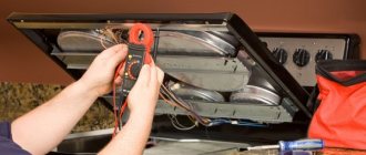
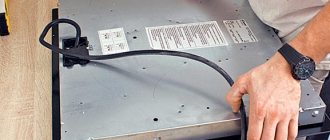
Then you need to carefully remove the decorative surface to gain access to the insides. Regardless of the manufacturer’s brand, prepared induction cookers look like this:
We carry out an external inspection. Any traces of soot, discoloration of components, traces of temperature tarnish on the metal should raise suspicion. The problem must be looked for from external manifestations.
If nothing suspicious is found, we follow the algorithm “from simple to complex:
Tip: the repair process will be greatly simplified if you have a schematic diagram of the electrical part at your disposal. It can be downloaded from specialized repair sites or from the manufacturer’s portal.
It doesn't matter that it may be in English (most likely it is). Any novice master who knows how to read diagrams will easily understand it.
It would be a good idea to photograph every step, especially before dismantling each unit. Subsequently, you will not make errors during assembly.
- We check the power supply: cable, contacts, fuse block. For this you need a multimeter.
- We carefully examine the spirals of the induction coils. There should be no cracks, contact between the turns, or foreign conductive objects.
- Together with the coils, we inspect the temperature sensors. It is quite difficult to check them without an electrical circuit, but they work on the principle of a thermistor. As it heats up, the resistance should change (a multimeter will come in handy again).
- Then we test the serviceability of the connecting wires from the induction coil to the generator. We check the circuits with a multimeter.
- We inspect the control board. Often cracks appear on it (when exposed to temperature), which lead to rupture of current-carrying paths. To do this, you will need a powerful lamp (in the light) and a magnifying glass.
- We remove the potentially problematic burner in the housing with the generator board. We examine the element base. Burnt radio components are usually immediately visible.
- When, due to burning, it is impossible to make out the denomination, it is impossible to select a part without a paper diagram.
- If an electronic element is identified, it is not necessary to look for exactly the same one (the manufacturer does not matter). It may be too expensive or in short supply. There are databases on radio components on the Internet: “datasheet”. On these resources you can easily find an analogue.
- If you have identical burners, you can replace the generator board to find the faulty element by elimination. You will know exactly what has failed: the control or the inductor.
Error codes
Induction cookers give errors that can be recognized by special codes. But different manufacturers have encrypted different codes specific to each model. Let's consider the well-known ones - Electrolux, Combustion, Bosch and Kitfort. The induction cooker produced by Electrolux has the following codes with decoding:
- L – “child protection” is turned on;
- F – burner without cookware of a suitable type (usually this icon flashes);
- E1 – the maximum permissible temperature has been exceeded near electronics;
- U3 – no connection with the inverter;
- E4 – the maximum permissible temperature of the burners has been exceeded;
- E5 – network error;
- E6 – communication with the power unit is not established.
Errors from the Combustion manufacturers are as follows:
- EF35 – the induction power board is damaged;
- U – the burners are turned on with an error (the abbreviation should blink in this case);
- E – the burner has overheated;
- E (ER) – problems with electronics.
The Bosch induction cooker produces the following error codes:
- E22 – there are foreign objects on the surface of the stove and it is faulty (dirt, carbon deposits, food residues, moisture);
- E25 – power board malfunction;
- ER is high voltage, which is unacceptable in this case.
The board for Gorenie brand equipment produces the following codes:
- F1 – short circuit;
- F2 – measuring circuit damaged;
- F6 – no connection with the power board;
- F15 – temperature sensor is faulty;
- F16 – failure of the power supply;
- F18 – control sensor is broken;
- F85 - the electronic module has overheated.
Errors on the Kitfort stove are as follows:
- E0 – there is no suitable type of cookware on the stove;
- E3 – the voltage is too high, all permissible standards are exceeded;
- E4 – not enough voltage;
- E5 – the surface is overheated or there are empty dishes on the stove.
The most “popular” and real malfunction
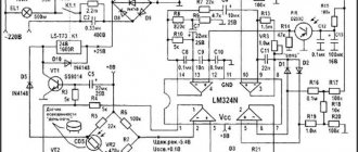
If you look at the simplified diagram, it becomes clear that one of the important components is the control transistor T1 of the output stage (the same one that is cooled by the radiator).
It is he who is susceptible to thermal overload, especially when using cookware of a smaller diameter. The operation of the circuit is designed in such a way that with an increased load on the induction coil, the operating current of the transistor sharply increases. A burnt-out part is not necessarily diagnosed visually, since the radiator is in place and is effective. Therefore, if there is a suspicion that the transistor has failed, it must be checked individually.
Using a multimeter, you can easily identify the fault and replace this critical part.
Another contender for elimination is the power capacitor. In a simplified diagram it is designated as Cr. It works directly with the induction coil, and is also subject to overheating.
The algorithm is the same: if there are no traces of breakdown on it, unsolder it and check it with a multimeter.
Expert advice
Experts advise adhering to the following recommendations:
- If the furnace does not work completely and does not respond to voltage changes, then this does not indicate a serious breakdown, the elimination of which will have to cost a fair amount of money. Often the problem is mechanical damage that can be easily eliminated: breaks, kinks, frayed wires. Cases of cable breakage are less common. This option implies the only possible solution - replacing the faulty wire with a working one.
- If the cable check does not reveal any faults, it is necessary to remove the hob from the countertop surface. To do this, unscrew the mounting strips, carefully lift the panel, and disconnect all the wires. This action will help you carefully remove the stove, and then delicately put it back in place.
- If your induction hob clicks while cooking, you should first read the instructions. For some models, such “sound accompaniment” is the norm, and its absence, on the contrary, indicates a possible malfunction. You should also not worry if the device hums, crackles or beeps. If the surface is very hot, it is worth checking that there are no foreign objects on the stove, for example, a spoon for stirring the dish.
- Contacts, cable and fuses are assessed with a multimeter. Detecting resistance on a piece of wire indicates that it is 100% faulty. In this case, the induction coil coils need to be replaced. The tool checks the permissible temperature. It is also important to test the wiring running from the induction coil to the generator. Check with an ordinary powerful light bulb and a magnifying glass. These tools will show you if the control board is cracked. The latter provoke a break in the paths carrying current.
- To repair an induction cooker, you need to prepare diagnostic tools, a soldering iron and soldering devices. The cause is either improper operation, a manufacturing defect, or liquid getting inside the housing.
The failure of the pit makes owners wonder whether it is possible to carry out repairs on their own, without the hassle of transporting the equipment to a service center. On our website you will find advice from our experts on how to repair timers, glass, oven doors, electrical appliances with ceramic and glass-ceramic surfaces, gas stoves and ovens, as well as electric stove ovens.
Anyone can repair an induction cooker with their own hands. But any repair begins with studying the instructions. By strictly following the given plan, you can discover the cause of the malfunction and replace the damaged parts with working ones.
Where to buy a new stove
You can resolve the issue as quickly as possible by visiting the nearest specialized store. The optimal option, in terms of price-quality ratio, remains purchasing from the AliExpress online store. Mandatory long waits for parcels from China are a thing of the past, because now many goods are in intermediate warehouses in destination countries: for example, when ordering, you can select the “Delivery from the Russian Federation” option:
| Induction electric stove Zigmund & Shtain ZIP-555 | DMWD Mini-stove electric, magnetic, induction | Induction hob Zigmund & Shtain CI 32.6 B |
| Induction hob Sakura SA-7152FS, 2000 W | Induction cooker, hob stove Bangdun AJ35 3500V | Portable Induction Cooker 2000W |
Cooling fan malfunction
The cooling fan may run continuously if you have set the heating power of the burners to maximum. It may also not turn off if the air temperature around it is more than 50°C. Otherwise, the malfunction may be caused by a faulty control unit that must be replaced.
In this case, the unit may also display error codes on the display. For a faulty fan, this will be error code “E7”.
The opposite situation also happens - the fan does not turn on. This behavior can be considered normal when the power level of the hob is minimal. It should turn on when the air temperature around it rises above 50°C. To check the fan, a test program is launched. If it shows that the mechanism is out of order, then it needs to be replaced.
Types of breakdowns
Types of induction cooker breakdowns can be both simple and complex. For example, reasons for partial inclusion of a product include:
- The socket into which the induction oven is connected is not working. To verify this, a known working electrical device is connected to it.
- The power wire has burnt out. This sometimes happens if the manufacturer for some reason installed a defective cable. To check, a multimeter is used, which tests each wire for resistance. Zero on the multimeter scale indicates that there is a break in the cable. This means that it will have to be completely changed. If you don’t have a multimeter at hand, take another cable and install it in place of the old one, plugging it into the socket. When the panel works, it means that you are on the right path to fixing the problem.
- Broken contacts. Quite often there are cases when they burn. To believe this, you need to open them, clean them with alcohol and reinstall them.
- Damaged fuse. This small element burns out during power surges. And if there are power surges on the line into which the house is powered, then most likely this is the reason for the non-functioning kitchen appliance. In this case, the fuse is replaced with a new one.
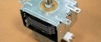
- Non-functional transformer. This is one of the most important elements of induction cookers, which is responsible for the currents inside the coils. It, like all other electrical parts of the stove, is checked with a multimeter for the presence of resistance. The nominal value of this indicator is indicated in the product passport. If zero appears on the multimeter display, then a short circuit has formed between the windings of the transformer. If “infinity”, then a gap has appeared in the circuit.
Below is a list of common defects in induction cookers that affect the functioning of the device.