0
4012
28.05.2019
To create automation of many processes, special devices called time relays are produced. The article describes in detail their purpose, technical characteristics, how to use, what types there are, advantages and disadvantages, and how not to make a mistake when choosing products. Also included are diagrams for connecting the device and how to do it yourself.
What it is
A time relay is a device based on the battery principle. It often functions as a switch and breaker. The operating time of this device can be hourly, daily or weekly. Many types of switches are equipped with an electromagnet to mechanically operate the switch. There are also solid-state relays, which have no mechanically moving parts. By using low voltage levels applied to the control terminals, such devices are used to turn a high-power circuit on and off.
When electric current passes through the coil, it generates a magnetic field. The field activates the armature, and subsequent movement of the moving contact (or contacts) creates or breaks (depending on the design) a connection to the fixed contact. If the group of contacts was closed when the device was de-energized, then the movement opens the contacts and breaks the connection, and vice versa if the contacts were open. When the current in the coil is turned off, the armature returns with a force approximately half that of the magnetic force to its natural position. Typically this force is provided by a spring, but gravity is also widely used in industrial motor starters. Most of these devices are manufactured for faster operation. In low voltage conditions it reduces noise, and in high voltage conditions it reduces sparking.
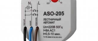
Typically, 12 V, 24 V and 220 V time relays with turn-off delay are produced and produced.
Answers to the 2 most asked questions
- Question.
Are there any analogues for ne555?
Answer:
Yes very many. All are similar to each other, like two peas in a pod in terms of internal architecture. KR1006VI1 - the closest domestic analogue of ne555
- Question.
How does a relay work?
Answer:
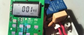
the relay consists of an armature, electromagnets and switching elements. When a current of the required magnitude is supplied to close the contacts, the armature closes - the relay begins to pass current. When the control current decreases to the cut-off value, the armature opens to its original position due to the constant mechanical spring pressing on it - the current stops flowing.
Where and how it is used
220V time delay relays are common in the areas of electrical power distribution and generation. The protection they provide to high-voltage lines creates trouble-free operation of substations, as well as other equipment.
Protection control elements are manufactured for connection switching at very high operating voltages (several thousand Volts).
Thanks to the installation of relay protection, it is possible to back up power lines, as well as instantly disconnect damaged or dangerous sections of power networks.
Electromagnetic type devices are widely used in various types of household appliances, such as washing machines, refrigerators, etc.
Today, time relays of this type are widely used in control systems for production and conveyor lines. Such control systems are usually used in industries with high parasitic potentials, at which control of semiconductor systems becomes impossible.
RF with switch-off delay 220V with 3 best devices from aliexpress
Buying a relay on the aliexpress portal saves money. We present three of the best devices on this service.
| Number in the rating | Name | pros | Flaws |
| First | Digital LED Display Time Delay Relay Module Board DC 12V Control Programmable Timer Switch Trigger Cycle Module With Case | Digital indicator, presence of housing | To control 220V devices you need an intermediate relay |
| Second | AC 220V H3Y-2 Power On Time Delay Relay Solid State Timer 1.0~30 Min Socket Base | Ability to work on a 220 V network, convenient setup | Limit delay time 30 min |
| Third | Programmable Delay Relay DH48S-S with socket base | Unlimited exposure time, presence of housing, possibility of remote adjustment | Price |
Number one, two and three in our relay rankings
Design Features
- Coil.
- Fixed magnetic circuit.
- Armature (coil or moving part of the magnetic circuit).
- Release spring and block contacts.
- Adjustment screw.
- Traverse.
In the place where the armature and the core come into contact, a non-magnetic gasket is placed. It is needed so that the anchor does not stick directly to the core. If there is no gasket, then the rebound spring will not be able to withstand the holding force of the residual magnetism of the core. In this case, the device will not be able to turn off.
The delay time of a time relay is the time from the moment the pulse is applied to the coil itself until the period of contact activation. Adjustment of the shutter speed is done by changing the thickness of the gasket and tensioning the tension spring using a screw, depending on the type of device. The duration of exposure depends on the thickness of the spring tension and the thickness of the non-magnetic gasket. The lower the voltage and the thinner the gasket, the longer the endurance.
Programming microprocessor devices
As described earlier, microprocessor devices became a milestone in the development of time relays. The essence of what they are needed for is the versatility of the device. It can be programmed to perform the functions of turning off, turning on, maintaining line activity for a set period, and all of the above can be done without changing the design of the device itself. Any complexity of operations will be performed using just one microcircuit located on the device board.
In addition to these features, a nice bonus is the expansion of functionality through communication interfaces with smart home systems. The latter can not only monitor the state of the time relay, but also set its parameters or directly influence the shutdown mechanisms.
For example, a universal two-channel programmable time relay UT24 from the Aries production association is shown in the picture below:
To program its timers, you need to refer to the block diagram and follow the steps; you can find out the purpose of the configured item in the user manual, which comes with each device:
As you can see, microprocessor devices seem complex only at first glance, but once you understand a little, you can easily use them for your purposes and configure them.
Specifications
Dimensions of 12 Volt time relay with off delay: 65x36x23 mm.
Dimensions of the device 220 volts with switch-off delay: 68x86x18mm.
- Mains voltage. Limits: upper – from 220 V to 280 V, lower – from 120 V to 210 V.
- Supply voltage ranges from 100 V to 420 V.
- Rated current – 5 A, 16 A, 25 A, 32 A, 40 A, 50 A, 63 A.
- Current consumption – 2.8 mA, 5.8 mA (for the SR 1 model), 10 mA, 76 mA, 86 mA.
- Rated load power – 1 kVA, 3 kVA, 5.5 kVA, 7 A, 8.8 kVA, 11 kVA, 13.9 kVA.
- Load connection delay period (adjustable) from 3 to 600 seconds.
- The load power off time during voltage reduction is from 1 to 0.04 seconds depending on the type of device. During voltage increase - from 0.01 to 0.05 seconds.
- The permissible number of starts (with a connected load) is from 50,000 to 100,000 times.
- For a three-phase design, it is possible to adjust the phase imbalance in the range from 10 V to 80 V.
- Adjustable time for a given skew from 0 to 30 seconds.
Protection Standards:
- IP 20 – protection of the device against penetration of objects with a diameter exceeding 12.5 mm into its body.
- IP 56 – protection against normal and strong water jets.
Operating principle
Table of degrees of protection
The main function of the RF is the formation of a time delay for switching control groups of contacts. The implementation of the delay depends on the design features of the device. There are many varieties of RV. From a functional point of view, they are pneumatic, motor, electromagnetic, electronic, as well as clockwork devices. They differ in parameters, appearance and installation method, and have the following technical characteristics:
- maximum switching current;
- rated switching voltage;
- type of contacts, their number;
- wear resistance (estimated number of inclusions);
- IP protection degree.
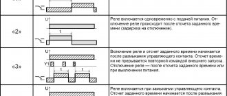
Devices are divided into devices with a switch-off or switch-on delay. Many relays have two options at once, changing the type of switching. The operating algorithm is as follows:
- During startup, the contact group is activated - the contacts are closed for the relay with a turn-off delay.
- The time delay mechanism is cocked.
- After the programmed interval has expired, the contact group changes order.
The on-delay relay works in a similar way. In cyclic type devices, a given sequence is repeated many times.
What are the types?
Electronic types
This is the most common variety. They have a process control function with a delay of a few fractions of seconds. The continuous operation time is several thousand hours. They are small, consume little electricity and have different additional functions depending on the manufacturer.
Electromagnetic retardation devices
They require direct current to operate. During the increase in the main magnetic current, the delay of the device is triggered, so another flux is created in the additional winding, which prevents the main one from increasing.
Pulse or bistable relay
—Pulse relays differ from electronic ones in that when a voltage pulse is applied to them, it turns on, when the next pulse is applied, it turns off. It is used in automation and security systems. When a pulse is given from one polarity, the armature occupies one position, simultaneously closing a pair of contacts. When a pulse of reverse polarity is applied, the armature occupies a diametrically opposite voltage, also closing a pair of contacts.
Pressure switch
—Pressure switch—designed to automate the water supply system. It is responsible for turning the pump on and off automatically when the water pressure changes
With pneumatic retardation
This type has a pneumatic damper. To adjust the time, you need to change the cross-section of the hole. These devices have a large number of contacts that can transition from a normally open to a normally closed state. This type of switch is used where sequential control is needed. Their coils are easily replaced, and the time delay ranges from 0.4 to 180 seconds.
Devices with a clock or anchor mechanism
They work using a spring that is driven under an electromagnet. The anchor mechanism begins to work when the specified time is set on the scale. The 2РВМ device is a classic representative of this variety. Its purpose is to control two electrical circuits (independent) for closing and opening. They are controlled thanks to daily programs, which are installed by installing pins in two special disks.
Motor devices
They are distinguished by a high time delay - from five seconds to three to five hours.
Software relay
It is used for communication of electric motors, automation of local circuits and lighting loads. They differ from other types in that the contacts are made of silver, and from programmable logic controllers in a small number of input/output channels, a small amount of memory and the inability to perform complex mathematical operations.
Time relay for automatic load shedding
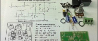
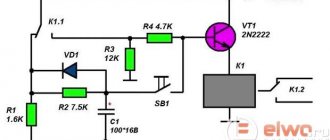
Sometimes it is necessary to turn off the receiver or backlight after a certain period of time. This problem can be solved by the circuit shown in Fig. 1.
Rice. 1. Timer circuit for automatic load shutdown.
With the ratings of the timing elements indicated in the diagram, the shutdown delay will be about 40 minutes (for micropower timers, this time can be significantly increased, since they allow R2 to be set with a higher rating).
In standby mode, the device does not consume power, since transistors VT1 and VT2 are locked. Switching on is done by button SB1 - when pressed, transistor VT2 opens and supplies power to the microcircuit. At the output of timer 3, a voltage appears, which opens the transistor switch VT1 and supplies voltage to the load, for example, to the BL1 lamp.
The button is blocked, and the circuit will remain in this state while capacitor C2 is charging, after which it will turn off the load. Resistor R3 limits the discharge current of the timing capacitor, which increases the reliability of the device. To obtain large delay intervals, capacitor C2 must be used with a low leakage current, for example tantalum from the K52-18 series.
How to choose
Main criteria for product selection:
- The packaging must be undamaged, clean and dry.
- Mandatory presence of a barcode (and/or QR code).
- Correct spelling of the product name and manufacturer.
- Availability of passport and/or instructions.
- All technical specifications are contained on the box or in the passport and/or in the instructions
When choosing a device, it is important to pay attention to the following characteristics:
- manufacturer's reputation;
- permissible voltage limit;
- power;
- level of protection against moisture and dust;
- operation limit;
- absence of any damage to the case;
- power source (mains or autonomous).
Operating principle of protective devices
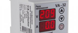
To protect against electrical impulses caused by lightning, a lightning arrester is installed together with an SPD. And you can protect the line from the flow of electrons, the parameters of which do not correspond to the operating characteristics of the network, using special sensors, as well as overvoltage relays.
It should be said that both the DPN and the relay differ in principle of operation and purpose from the stabilizer.
The task of these elements is to stop the supply of electricity if the value of the difference exceeds the maximum threshold specified in the technical data sheet of the protective device or set by the regulator.
After normalizing the parameters of the electrical line, the relay switches on automatically. DPS for line protection should be installed only in conjunction with a residual current device. Its task is to cause a current leak when a malfunction is detected, under the influence of which the RCD will trip.
Visually about the voltage relay in the video:
The disadvantage of this circuit is that it needs to be turned on manually after the voltage returns to normal. In this regard, a voltage stabilizer compares favorably. This device provides an adjustable time delay for current delivery if it is triggered by excessive voltage. The stabilizer is often used to connect air conditioners and refrigeration units.
Examples of using
Let's look at some scenarios for using timers in real situations.
Lighting in the park, on the porch, in the house
Today this scheme is very popular. When organizing a lighting system in a park or square, a motion detector with a timer is installed in the circuit (usually infrared, as the simplest and most reliable).
When a person appears in its field of vision, the sensor is triggered and sends a signal to the relay that turns on the lights. At the same time, the time counter is activated, and when the specified interval has elapsed, the lamps go out (provided that the sensor does not detect new movement). This achieves two goals:
- energy savings;
- path lighting on demand.
Schemes are implemented in a similar way in residential and non-residential premises.
Automatic hood
This scenario has already been discussed above. A motion sensor is also used here. When people appear in its field of vision, it starts the exhaust system and freshens the air in the room. When people leave, a time relay turns off the device after a certain period.
Electronic locks
Many modern locking systems are equipped with a timer that closes the lock after a set period of inactivity.
Smart plugs
A socket with a built-in electronic time counter is capable of turning off the load connected to it according to a schedule or the results of monitoring energy consumption parameters. As already mentioned, this allows you to avoid troubles due to forgotten electrical appliances.
This is just a small list of examples of using timers - their scope is very wide.
Scheme for 220 Volts
Timers on transistors and microcircuits operate from 5–14 V (standard from 12 V). 220 Volt time relays are diode assemblies with magnetic starters. If the equipment being serviced is low-power (for example, lighting, lamps, soldering irons, boilers, small motors, etc.), then the latter need not be installed - the diode bridge and thyristor transform the voltage themselves.
Let's look at the light bulb timer, the main parts: diode bridge, thyristor. It is not recommended to connect any other load: the thyristor will only pass a positive sinusoid of 220 Volt variables. This is enough for the listed consumers, but other electrical appliances may not be able to withstand it.
What you will need:
- resistors: 4.3 mOhm (R1), 200 Ohm (R2) and adjustable 1.5 kOhm (R3);
- 4 diodes with max. current from 1 A, reverse voltage from 400 V;
- capacitor 0.47 µF;
- thyristor (analogs are possible) BT151;
- regular microswitch.
The principle is standard for such assemblies: gradual charging of the AC. C1 (starts after activation of S1). Thyristor VS1 is open, and load L1 receives 220V from the network. After charging, it closes, cutting off the current - the lamp turns off. The pause is regulated by setting the value to R3 and selecting capacitance C1.
The assembly has a disadvantage: touching any exposed wiring or leg can result in a strong electric shock, since the elements receive a strong current.