In some cases, industrial and sometimes household single-phase lines are powered from a network with three or four phases. In order to select a phase with a voltage corresponding to the line parameters, an automatic phase switch is installed in the circuit. This device ensures uninterrupted power supply and also protects connected devices from surges that can cause equipment failure. The automatic phase switch is connected to a three-phase or four-phase network, through which electricity is supplied to a single-phase line. One of the phase conductors at its output is connected to the protected circuit. When the voltage parameters on it go beyond the normal limits, the device switches the power supply to power from another cable.
Switch operation order
An automatic switch is a digital device based on microprocessors. The device is durable and highly accurate, allowing for reliable protection of equipment connected to the network.
When connecting the device to the line, any phase conductor can be selected as the supply conductor.
To prevent the contacts of the output relays built into the device from sticking, the device is equipped with an internal lock. In addition, it monitors the state of the contactors of the starters, which are located in the external electrical circuit. Using this device helps prevent phase overload.
Design and operating principle
Structurally, the device includes input and output contacts, indicators of normal power supply and emergency, regulators, indicated in the diagram by the corresponding numbers (Figure 1):
- Emergency indicator;
- Indicator of connected load power supply;
- Potentiometer allowing you to select the desired mode;
- Asymmetry level regulator;
- Voltage reduction regulator;
- Potentiometer that allows you to adjust the time setting.
Not all models provide the full range of settings for the above parameters. They depend on the purpose of the specific relay and the scope of application.
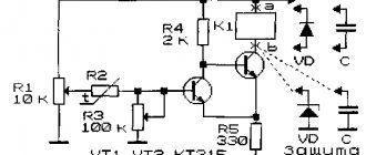
Rice. 2. Schematic diagram of operation
In normal mode, voltage is supplied to the power circuit from the EMF source E1 (Figure 2) to the consumer, be it an engine, a machine tool or other equipment. The phase control relay R is connected to the tap through the corresponding terminals, designated in the diagram as L1, L2, L3 and the neutral wire N. A logical circuit on transistors is assembled inside the device, which sends a signal from the output contacts to break the starter coil P to turn off. If necessary, the shutdown signal can be configured to both de-energize the consumer and disconnect the external electrical network.
In the event of an emergency - loss of one of the phases, short circuit, sharp increase in currents, the harmonic component of the electrical parameters of the network changes. To which the protection device reacts and sends a corresponding shutdown signal through the power circuits through terminals 24 and 21 to the contactor coil.
After the activation of power contacts in the practice of power supply to consumers, a natural restoration of the parameters of the supply network can occur, during which phase alignment will occur. In this case, the relay will return the contacts to the on position, due to which the automatic reclosure system is implemented and the voltage supply to the windings of the motor or other consumer will be resumed.
Using the “Start” and “Stop” buttons, you can manually control the power of an electrical device.
ADF installation parameters
The following settings are typical for the models of these devices:
- Limit voltage (upper and lower). The maximum voltage indicator is the most significant, and it is important to choose it correctly without making a mistake when setting it up. If it is too low, the device will constantly operate, and if the selected value is too high, overheating of the internal wiring is inevitable, which can lead to a fire.
- Priority phase of ACE. If there are no voltage drops on it, the device will not switch to other lines. In the event of a power surge, the line power will be switched to another conductor, but at the same time the device will continue to monitor the priority core. When the potential difference across it is normalized, the load will switch back.
- On time. This term refers to the delay period after the voltage disappears on all current-carrying conductors. When it expires, the device will try to turn on the power again.
- Return time. This is the interval after switching the power from the priority core to the backup one, after which the device will check the main phase, and if its parameters are normal, switch the power supply to the line to it. If the priority conductor is not ready to connect the load, the test will be repeated after the same time period.
Phase switch Novatek-Electro PEF-320
At the end of February, I had a review of the PEF-301 phase selection relay and, as I wrote then, I have been using these relays for a very long time and am completely satisfied with their performance. But a newer version, PEF-320, came across my desk. One of the key differences is that there is no ability to control external contactors, but more details, as always, are in the review. To be honest, at first I was skeptical about the new version, it costs more than PEF-301, it cannot control external contactors, but after a careful examination and modeling of possible application scenarios, I came to the understanding that, in principle, the manufacturer was quite right in releasing such an option. As the review progresses, I will try not only to show this model, but also to compare it with PEF-301.
The link in the header leads to the Ukrainian version of the site; for Russians the link will be different.
The relay is sold in a branded box, and the inside of the box is made so that the relay is firmly fixed and does not dangle in it.
The delivery set is extremely laconic, a relay and a passport with instructions.
User manual, connection diagram, warranty card, all this is available at the link in pdf.
In order not to download the instructions for the sake of characteristics, I will duplicate them here.
Like PEF-301, a warranty period of 10 years is stated, unfortunately (or fortunately) I was not able to verify this statement, since even the first relay, purchased about the same 10 years ago, still works normally in conditions that are by no means hothouse conditions.
But let's return to the subject of the review.
The first key difference from PEF-301 is the size. If the previous model took up 4 spaces in the panel (70mm), then this one is exactly twice as narrow, 2 modules (36mm). At the top there are four connection terminals - three phases and zero, at the bottom there is also a four-pin terminal block, an output phase and zero, but I will return to the latter a little later. The terminal blocks are exactly the same as those of PEF-301, a wire with a cross-section of up to 2.5 mm is normally clamped, in extreme cases you can insert 4 mm kV, but it is better not to do this. There are ventilation slots at the top and bottom.
There is a connection diagram on the side, a small thing of course, but useful; PEF-301 did not have it.
A visual comparison with PEF-301 and a pair of AB. Here I should note that the print on the body of the PEF-320 is a little paler; in my opinion, it can be critical when looking at the inscriptions near the “twisters” when you are working somewhere in a place with not very good lighting. In its own way, of course, it’s a quibble, but the PEF-301 has higher readability of the inscriptions, and this is especially noticeable when they are placed next to each other. To be fair, the same applies to AB Schneider located to the right.
The mounting mechanism on the rail has been changed, a spring has been added so the relay can simply be snapped into place.
The indication, number and purpose of controls are completely identical to those of the PEF-301; due to the smaller size of the panel, they were simply rearranged differently. But I’ll give a plus for the marks on the knobs of the regulators; with the PEF-301 I had to look closely at what position the regulator was in because the mark was black on black, and in fact, even in the photo it’s difficult to understand what it’s set to. In addition, the PEF-320 has light guides on the front panel, and not “bare” LEDs like the PEF-301. It seems to me that taking this into account, as well as the different design of the regulators, the security of the front panel has become higher.
Since the control is no different from PEF-301, I will duplicate the adjusted description from the previous review. Indication Three green LEDs show which relay is currently active, there are four activity options - 1, 2, 3, 0. One red LED shows the presence of an emergency input state and counting the pause time before returning after voltage normalization.
The control consists of four variable resistors: Umax
— Setting the threshold of the maximum permissible voltage at the input, the setting range is 230-280V.
Umin
— Setting the threshold of the minimum permissible voltage at the input, setting range — 160-210V
Tr
— Pause time before moving to the previous phase.
Those. if the relay has switched from the first phase to the second in the process, then when the voltage in the first phase is normalized, it will not switch to it immediately, but after a set time; if you select the extreme right position (infinity), then there will be no automatic transition. Adjustment range 5-200 sec + infinity. Тon
— Output turn-on time after emergency shutdown. This function is necessary if the relay is connected to equipment that cannot be supplied with power immediately after removal, for example, refrigerators. Adjustment range 1s-10min.
But personally, of course, disassembly is much more interesting to me; I was especially curious how the manufacturer packed the filling from PEF-301 into a body half the size. The relay is relatively easy to disassemble: first, the lower part is removed, it is secured with latches, then the board is pulled out about 5 mm and then inserted back. after the previous step, the knobs of the regulators will protrude by the same 5mm and you can remove them one by one. Once the handles are removed, we take out the board.
Yes, the layout is clearly denser, but in some ways even a little neater.
Inside you can see capacitors, a voltage converter microcircuit, as well as heat-shrinkable components. Later I found out that a 380 Ohm diode + resistor were hidden in the heat shrink and, as far as I understood, the resistors act as a limiter for the charging current of the capacitors and fuses, since the latter were not found on the board.
All components are placed on three boards, the main one contains the power part and the power supply system, on the left (they are labeled) a microcontroller, measurement circuits and one of the relays, but on the right, only three trimming resistors were left.
In addition, on the central board there are relay control transistors and other small things.
In general, the layout is really dense, but in general it turned out even somehow neater and more monolithic than that of PEF-301.
There are protective slots near the input and output terminals, and they are also present between the contact pads of the relay; they obviously didn’t spare any solder, so there’s no question here, almost...
I have a question about the marking of the output terminal blocks. The connection diagram clearly says to use the outer terminals, but if you look at the photo above, you can see that the terminals are used in pairs. At the same time, pairwise use, in my opinion, is a big advantage since you can connect two loads without using intermediate elements. Perhaps there are some nuances, but as for me, it was possible either to put the letters L and N in the middle between the terminals, or to designate each terminal individually - LLN N. Moreover, it would be clear that these are terminals of the same name, since the diagram is viewed at most only when installation, and the text description is generally read when “everything has already burned down.”
Here we use relays manufactured by Omron G2RL-14-E with a 24-volt winding, but as I understand, this has nothing to do with the design or features of the relay itself, they can simply install either them or Fujitsu.
Structurally, there is no difference between the relays.
But as far as I can tell, there is a slight difference in the characteristics, Fujitsu claimed 50,000 cycles, Omron 30,000.
The declared contact resistance is no more than 100 mOhm, judging by the datasheet, it is checked at a constant current of 1A and a source voltage of 5 volts. I also carried out a similar test, in the end I first got a drop of 1.6 mV on one relay and 3.6 on the other, the third relay was tested due to the fact that the test took place in the housing. The total drop is checked on the first and third phase, as far as I can tell from the diagram, the shortest and longest path are about 6 and 12 mV, respectively. The calculated contact resistance turned out to be noticeably less than the declared value, about 1.6-3.6 mOhm, the total drop across the entire device at a current of 16A will be 96-192 mV, power loss 1.5-3 W, approximately the same values were obtained for PEF-301.
But in fact, the actual drop on the contacts is noticeably smaller. The thing is that, due to the characteristics of the test and the equipment, I first turned on the relay, it closed the contacts and only then supplied current; when switching under current, the situation will be better since oxides break through more easily. The datasheet specifies only the current/voltage values, but does not specify the methodology, so I gave both results. The photo shows the same contacts, the same current, in the same sequence.
The side boards are soldered, but I was very curious, so I had to take a soldering iron and partially disassemble the structure.
The second key change, PEF-301 used a power supply circuit with quenching capacitors, but apparently putting it into such a box was completely problematic because now the power is provided by the LNK305PN PWM controller. There are filter capacitors nearby and initially I wanted to swear, since they are rated at 400 volts, but then I looked more closely and found out that they are connected in series, i.e. Formally, there is a 2.35 µF 800 volt capacitor at the input. The thing is that Power Integrations controllers are quite resistant to high input voltage; for example, my TOP series could withstand 380 volts at the input of the power supply, and the controller simply blocked. It is clear that there were problems with the input capacitors, but I did not count on such situations.
Here, of course, the controller is of a different series; moreover, it’s essentially just a StepDown, but with a high-voltage input. Unfortunately, I didn’t find any indication in the datasheet about the presence of OVP protection, so I can’t say. How will it behave at high input voltage, but the fact that there is a margin on the input capacitor is already good.
I didn’t redraw the circuit, but it doesn’t look much different from the one shown in the datasheet, only instead of C4 there is an X2 type capacitor, which in my opinion slightly limits reliability. The converter receives power from terminals L1-L3 through diodes, i.e. three-phase half-wave rectifier.
Another change, although not so significant, is that the voltage divider resistors are now SMD, but there are also no complaints here, they are installed in threes in series, and since for the 1206 case the maximum voltage is 200 volts, we have a divider rated up to 600 volts . The rest of the circuitry is identical to PEF-301.
Let's move on to the tests. When voltage is applied, the red LED first lights up and if the voltage is normal, then the delay time starts counting and then it turns on the corresponding relay. Let me remind you that input L1 is priority.
My wattmeter, of course, is not very accurate, but it shows a power consumption of 1.1W, the passport stated 1.2W. Just for fun, I turned it on for about an hour and then measured the temperature inside; in my case, the hottest was the first relay, responsible for line L1.
At an input voltage of about 14.5 volts, the device tries to start by blinking the LED, and at 16 volts it enters operating mode. Of course, there is no special meaning in such a range, but it certainly won’t make it any worse.
The accuracy of setting the thresholds also did not raise any questions; for starters, checking the protection against voltage drop below the setting. 1. Setting 160V, switching off at 160, switching on at 167 2. Setting 180V, switching off at 180V, switching on at 187.
Overvoltage protection. 1. Setting 250V, switching off at 250, switching on at 245. 2. Setting 255V, switching off at 255, switching on at 250.
The behavior during voltage drops is also identical to PEF-301, as last time I conducted an experiment with a light bulb and a low-power isolation transformer, which is why when the relay was turned on, the voltage dropped from the original 205 to about 155-160.
Here, similarly, with other threshold settings, a delay of 12 seconds was obtained, but sometimes the relay behaved in a way that was not entirely clear; with unchanged settings, there may or may not have been a delay. I was interested in this point and I decided, just in case, to clarify this nuance with the manufacturer, to which I received the answer:
0.02s switching - occurs if the voltage drops sharply by 60V below the lower threshold. If the drop is smooth by a small amount, then switching occurs in 12 seconds.
Those. this is influenced not only by the value of the voltage drop, but also by the rate of its decrease, so in the experiment I simply hit the edge of the threshold for determining an accident. In any case, this situation is normal.
Emulation of voltage loss/appearance in the first and second phases, everything is the same as in PEF-301.
The demonstration of running across the entire range turned out to be a little longer due to the wider voltage range on the smaller side. The relay also clearly processes the transition to threshold voltages.
This time, oscillograms of the switching process were taken for two switching options. 1, 2. Switching from the first input to the second when the voltage at the input is removed. Most often, the switching took about 60ms, but sometimes it lasted up to 80ms, and usually the switching occurred at the beginning of the positive wave of the sine wave, but at least one time out of four it fell on the negative half-wave. 3, 4. Return to the working input, i.e. fully initiated by the device, here in all tests the transition took one half-wave in time, and the negative one always occurred.
Everything is the same, but to switch from the first to the third input (the second was de-energized), in fact, all of the above can be repeated one by one.
After I checked everything I could get my hands on, I can say the main thing - the key difference between PEF-301 and PEF-320 lies in three things: 1. Dimensions, PEF-320 is exactly half the width, which is very critical in small shields 2. Power system, PEF-301 has quenching capacitors, PEF-320 has a PWM controller, which is better, it’s hard to say. 3. PEF-301 can control external contactors, but PEF-320 cannot.
Everything else is just cosmetics and the tests were just to make sure of this, although in fairness the “twist” of the PEF-320 is more convenient, or rather, they are more visual.
There are also some minor drawbacks, I would like: 1. Perhaps a little more contrasting inscriptions, for example, like in PEF-301 2. Markings on the case for all four output terminals, and not just the outermost ones, since they are connected on the board, then to what extent I understand that it is possible to use them. 3. I would still think about installing a fuse in front of the PWM controller, or rather, between the connection point of the rectifier diodes and the rest of the circuit elements; I don’t see a problem finding some space for it.
Regarding point 2, a company representative later commented on the situation:
The reason why the information on the label was removed is banal. We received negative experience (for other products) with this solution, namely, many customers, seeing a free terminal N, screwed a conductor from another load to the terminal. Thus, they organized transit through our product and exceeded the current characteristics. As a result, transit burns out and we receive a complaint.
Actually, this is still the same time-tested PEF-301, and in my own way I’m glad that by changing the design the manufacturer did not make it worse, as sometimes happens.
Well, as for the application scenario, I plan to use this relay to control the power supply of a video surveillance system at one of the facilities and again as an automatic transfer switch. The situation is simple, a house outside the city, an unstable network, but there is a generator and some other source (not yet known), the security switches manually, but sometimes they can forget something. Since the load is small, external contactors are not needed, and all sources have a common zero. During switching and other things, there will be a UPS after the relay.
That's all for me, I hope it was useful.
Features of connection and operation of the device
The automatic switch is installed immediately after the electric meter. The device connected to the line tests the condition of the conductors and connects the circuit to the core whose parameters best correspond to the required ones. During operation, the device constantly monitors the voltage, which should not go beyond the established limits.
Operating procedure and device of the phase switch in the video:
During operation, voltage control is carried out not only on the priority phase, but also on two backup ones. This is necessary so that if the parameters on the main conductor are violated, without delay, select another core to switch the power. If the voltage on both backup lines is within acceptable limits, switching proceeds from L1 to L2 and further (phase designations are on the device body, each has its own LED).
If the potential difference does not correspond to the specified parameters on any conductor, power will not be supplied through them. When the voltage on the priority line normalizes, the connection will be made to it first.
Video description
Automatic phase switch. An example of using PS-63 in a three-phase distribution panel.
A manual phase switch is often called a packet switch - it is a mechanical cam device where the toggle switch can be moved to one of three possible positions. That is, in the event of a power outage, surge or sag, you can transfer the power to the line from another phase manually by turning the toggle switch. This option is used in cases where the user is knowledgeable about electrics, but for uninformed users it is better to install automatic switches.
Equipment selection
This phase switch is designed to power industrial and domestic single-phase loads 230/240 V 50 Hz from a three-phase four-wire network (3x400+N) Source 220volt.com.ua
When choosing an electronic automatic three-phase switch, you must pay attention to the technical parameters of this device:
- First of all, you should pay attention to the fact that the parameters of the phase switch correspond to the parameters of the input current; these indicators determine the current strength (A), voltage (U) and resistance (Om or Ω). Under no circumstances should you use a device that has these parameters lower than the supplied input current.
- Modern PFs have additional functions. This is the regulation of the minimum and maximum voltage until the moment of switching, as well as the presence of a timer that allows interruptions in voltage within a specified time, after which the switch to the optimal phase occurs. Budget modifications of the PF do not provide for such improvements.
- Modern PF models, in addition to the segment indicator, are equipped with an LCD display that displays the main settings indicators, which includes the voltage value and the number of the phase connected in real time.
Note: there are significant differences between industrial and household automatic PFs in terms of various technical characteristics - you must pay attention to this.
Main types of ACEs
In modern networks in our country, the most common switch models are PF 431 and PF 451. Let us consider them in more detail.
PF 431
This device provides reliable protection of household equipment from voltage surges on phase conductors. It can be installed together with air conditioners, refrigerators and freezers, computers, alarm and video surveillance systems and other equipment that must be continuously supplied with electricity.
The device works according to the following principle. A three-phase voltage is connected to the APF input, and a single-phase network with parameters 220V, 50Hz is connected to the output. The device monitors the output potential difference, and if it goes beyond the established limits, it connects the line to a phase conductor whose parameters correspond to the norm. At the same time, control over the priority conductor, which for this model is L3, does not stop.
When the voltage on it returns to normal, the reverse connection occurs. If the potential difference on L3 is stable, power reconnection to the backup phases will not occur.
PF 451
This device is designed to ensure power stability of single-phase lines. It is used with various household equipment, like the PF 431, and works on a similar principle, which there is no need to describe again. The main difference between them is that the PF 451 does not have a priority phase. Therefore, a line with optimal voltage values is always selected for connection.
Operating principle and installation of an electrical circuit based on a phase switch on video:
Application area
Let us repeat that before ordering a switch, you should know that it requires 3 phases to operate. Reserve lines are taken from additional phases. Between phases the voltage is 380 Volts, it is called “linear”, and between phase and zero 220 Volts, it is called “phase”. They are related, but within the scope of this article we will not delve into the basics of electrical engineering. The main thing is for you to understand that to connect to electrical networks you need a three-phase network of 380 Volts.
As already mentioned, this device is used to connect a backup line. This only works if one of the transformer phases is overloaded or a imbalance has occurred. In cases where a “bad” voltage is supplied to the input transformer, automatic input of a reserve is required from another line; a phase switch will not help in this situation.
Units with continuous operation are powered from a phase switch. I propose to consider the scope of application in illustrative examples.
In medicine:
In production and in offices:
- automation tools;
- control and monitoring equipment, recording signals;
- communications equipment, stationary radio stations, dispatch equipment;
- ventilation systems;
In the house:
- a gas boiler;
- security system;
- CCTV;
- “smart home” system;
Specifications
Among the technical parameters implemented by the phase control relay, it is necessary to highlight:
- supply voltage;
- overvoltage control range;
- voltage reduction range;
- time delay limits for switching on after a power surge;
- time delay limits for switching on after a voltage drop;
- time spent on shutdown in case of phase loss;
- rated current at the contacts of the electromagnetic relay;
- number of contacts for performing switching operations;
- device power;
- Climatic performance;
- mechanical and electrical wear resistance.
The connection diagram determines the order of phase alternation, so normal power supply to the load is possible provided they are correctly observed at the installation and configuration stage. In this case, it is possible to adjust the switching delay for different operating modes of the device. Thus, for motors, at the moment of starting, it is possible to adjust the response delay time from 1 to 3 seconds to withstand starting currents.
The same applies to the possibility of adjusting emergency operation in case of phase overload, where the time before switching can be adjusted from 5 to 10 seconds.
Features of the PS-63A DigiTOP model
The PS-63A Automatic Switch is the latest and most advanced model available on the market for electronic selection of the best phase. Designed for a maximum transit current of up to 80A, nominal - 63A for input and output.
Produced by the renowned manufacturer DigiTOP, which is primarily known for producing only electronic devices with digital displays with additional control functions and only the highest quality, while keeping prices quite low.
This device has been incubated by DigiTOP developers for a long time, over the past three years. Competitors' models, their features and disadvantages were studied, a unique modular housing was developed and produced for the possibility of installing three-phase protection devices and switches on a DIN rail with three digital indicators - A, B and C and reliable elevator-type terminals up to 80 in a standard distribution switchboard. A.
As a result, a new generation of high-quality phase switch PS-63A was released, which currently has no analogues either in functionality or in quality of work and performance.
Device settings
Simple models have a minimal set of settings. They are not adjustable by the buyer. The algorithm for their operation is established by the manufacturer and cannot be changed. Complex, expensive models, on the contrary, have many customizable parameters.
Lower voltage limit
This parameter determines at what input voltage the switch to the spare phase will occur. For example, if the voltage in phase A is more than 180 V, then the consumer is connected to phase A. If it is less, then a transition to phase B occurs.
In simple switch models, the default value is 180 V. In more serious models, it can be adjusted, and the minimum voltage limit can be set to 120-200 V.
Setting up the device is usually done using adjusters for a Phillips screwdriver. They are easy enough to twist. Hence the popular name for such regulators is “twist”. Other switch patterns use buttons. There is no fundamental difference in the operation of these regulators. Therefore, the choice is a matter of ease of use.
Upper voltage limit
Setting the upper voltage limit is necessary for the same task as setting the lower limit. But in the case of an upper limit, consumers are protected from overvoltage.
If the voltage in the current phase becomes more than permissible, the device automatically switches to another phase. For example, if the voltage in phase A exceeds 250 V, the APF will switch to phase B with a normal voltage of 230 V.
Return time
The return time to the priority (main) phase can also be adjusted using knobs or buttons. This parameter determines how many seconds after normalization of the voltage in the main phase the AF will return to it again.
For example, in the network, for some reason, there is a long-term voltage drop in one of the phases. APF goes to spare. After some time, the voltage in the main phase takes on an acceptable value. But the switching device waits. And only after the return time does it return to the normalized main phase.
The reset time is necessary to avoid constant false switching of the device. This increases the service life of the internal relays and reduces the risk of damage to the load.
This setting varies greatly depending on the type of consumer. For example, for refrigerators it is recommended to set the return time to about 3-10 minutes. For incandescent lamps 1-2 minutes is enough.
Classification of phase indicators
Regardless of the scope of application, the following types of phase indicators are most widely used to check the correct connection of household or industrial electrical devices:
- Induction - represented mainly by outdated models such as I517, FU-2 and more modern modifications.
In essence, they are a simplified model of an asynchronous motor, the rotor of which is made of an ordinary disk made of light metals. When directly connected to the power supply, this indicator disk begins to rotate clockwise, otherwise the direction of rotation is reversed. Devices of this type are characterized by a long working life and ease of use. Some modifications are used to work with three-phase networks with a frequency of up to 1 thousand Hertz. Induction phase indicator - Devices that provide indication of correct switching using conventional incandescent lamps or LEDs are considered more modern.
They are smaller in size and therefore easier to use, especially at home. We note the imperfections of some models, which require connection to only two phases and a neutral wire; this somewhat complicates the work on determining the phase order. Phase indicator with indicator type - Microcontroller-type devices also deserve attention.
They are quite suitable for performing work at home and in production; the correct phasing is shown using the same light indicators. Microcontroller type phase indicator
I517M:
FU-2:
The principle of operation of all devices, except induction, is based on the effect of phase imbalance, in which different active and reactive resistance appears in different circuits. As a result, this leads to a change in the intensity of the glow of individual indicators or a complete refusal to turn on.
Review of popular phase control relays
- RNPP-311 relay is one of the most popular and suitable for networks in the post-Soviet space. The abbreviation stands for voltage, imbalance and phase sequence relay. Modern modifications, in addition to standard parameters, are also capable of monitoring voltage frequency.
- OMRON K8AB this model monitors not only the reduction, but also the excess of the voltage level, thereby performing the functions of a limiter or arrester, and much more effectively. It has a number of modifications that differ in response threshold adjustments and technical parameters.
- Carlo Gavazzi DPC01 is distinguished by two relays on the output terminals of the device. It has several points for adjusting various parameters, and a mode switch. Provides 7 possible functions for setting delays, intervals or cyclic functions.
- EL-11 relay controls the parameters of the electrical network and can be used both in closed heated and unheated rooms. They can be installed in any position, but require protection from direct exposure to sunlight and atmospheric moisture.
Using transfer devices on different networks
Each changeover switch of one type or another can only be used in an electrical circuit with certain parameters.
In the single-phase version, mainly bipolar switches are installed. When connecting to the generator set, you will need a power supply with an operating voltage set to three hundred volts. The devices have a negative resistance of about 50 ohms.
To create high-quality contact, it is recommended to use copper jumpers. At the very beginning of the installation, you should find out the presence of an electrical panel. The KK220 series or a similar modification can be used. In single-phase circuits, the use of reversing devices is not recommended due to the possible discrepancy between their performance and network parameters.
For laid lines with two phases, the expansion version of switching devices is best suited. In this case, the switches acquire universal qualities and are freely used in single-phase networks, without restrictions. The voltage limit for operation reaches 300 volts. A 200 V power supply is used as an element connecting all available parts.
Connection diagrams for single-phase asynchronous motors
With starting winding
To connect a motor with a starting winding, you will need a button in which one of the contacts opens after switching on. These opening contacts will need to be connected to the starting winding. In stores there is such a button - this is PNDS. Its middle contact closes for the holding time, and the two outer ones remain in a closed state.
Appearance of the PNVS button and the state of the contacts after the “start” button is released"
First, using measurements, we determine which winding is working and which is starting. Typically the output from the motor has three or four wires.
Consider the option with three wires. In this case, the two windings are already combined, that is, one of the wires is common. We take a tester and measure the resistance between all three pairs. The working one has the lowest resistance, the average value is the starting winding, and the highest is the common output (the resistance of two windings connected in series is measured).
If there are four pins, they ring in pairs. Find two pairs. The one with less resistance is the working one, the one with more resistance is the starting one. After this, we connect one wire from the starting and working windings, and bring out the common wire. A total of three wires remain (as in the first option):
- one from the working winding is working;
- from the starting winding;
- general.
We work further with these three wires - we use them to connect a single-phase motor.
With all these
Connecting a single-phase motor with a starting winding via the PNVS button connecting a single-phase motor
We connect all three wires to the button. It also has three contacts. Be sure to place the starting wire on the middle contact (which closes only during the start), the other two - on the outer ones (arbitrarily)
We connect a power cable (from 220 V) to the extreme input contacts of the PVNS, connect the middle contact with a jumper to the working one (note! not to the common one). That's the whole circuit for switching on a single-phase motor with a starting winding (bifilar) through a button
Condenser
When connecting a single-phase capacitor motor, there are options: there are three connection diagrams and all with capacitors. Without them, the engine hums, but does not start (if you connect it according to the diagram described above).
Connection diagrams for a single-phase capacitor motor
The first circuit - with a capacitor in the power supply circuit of the starting winding - starts well, but during operation the power it produces is far from rated, but much lower. The connection circuit with a capacitor in the connection circuit of the working winding gives the opposite effect: not very good performance at start-up, but good performance. Accordingly, the first circuit is used in devices with heavy starting (concrete mixers, for example), and with a working condenser - if good performance characteristics are needed.
Circuit with two capacitors
There is a third option for connecting a single-phase motor (asynchronous) - install both capacitors. It turns out something between the options described above. This scheme is implemented most often. It is in the picture above in the middle or in the photo below in more detail. When organizing this circuit, you also need a PNVS type button, which will connect the capacitor only during the start time, until the motor “accelerates”. Then two windings will remain connected, with the auxiliary winding through a capacitor.
Connecting a single-phase motor: circuit with two capacitors - working and starting
When implementing other circuits - with one capacitor - you will need a regular button, machine or toggle switch. Everything connects there simply.
Selection of capacitors
There is a rather complex formula by which you can calculate the required capacity accurately, but it is quite possible to get by with recommendations that are derived from many experiments:
- The working capacitor is taken at the rate of 70-80 uF per 1 kW of engine power;
- starting - 2-3 times more.
The operating voltage of these capacitors should be 1.5 times higher than the network voltage, that is, for a 220 volt network we take capacitors with an operating voltage of 330 V and higher. To make starting easier, look for a special capacitor for the starting circuit. They have the words Start or Starting in their markings, but you can also use regular ones.
Changing the direction of motor movement
If, after connecting, the motor works, but the shaft does not rotate in the direction you want, you can change this direction. This is done by changing the windings of the auxiliary winding. When assembling the circuit, one of the wires was fed to the button, the second was connected to the wire from the working winding and the common one was brought out. This is where you need to switch the conductors.
What it might look like in practice