The C32 circuit breaker is a circuit breaker that protects the network from overloads and short circuits. Also designed to manually turn on and off load currents. The machine is modular, because consist of separate single-pole blocks that can be used as single-phase or combined into two- or three-phase. This design makes it easy to assemble the required device of the required configuration. In case of breakdown, you can replace the individual damaged element.
General characteristics and markings of C32 circuit breakers
Single-pole circuit breaker C32
Many characteristics of the switch are indicated on its body. The main one is the rated current. This is the maximum current that the device passes in normal mode and for a long time. For the C32 machine it is 32 Amperes.
Another important characteristic is the ability of the protective device to turn off short-circuit currents of a certain value (switching capacity). After activation, the device must remain fully operational. The short circuit current is usually indicated in a rectangular box. For a 32 Ampere machine it is 4500 A, or 6500 A.
Industrial devices use additional characteristics:
- ultimate breaking capacity Icu—double operation current that does not damage the device;
- operating breaking capacity Ics - triple tripping current.
The higher the breaking capacity, the more reliable and durable the device.
In the process of disconnecting a short circuit, an electric arc flashes between the contacts of the switch. It has a high temperature and can destroy the device. Extinguishes using arc chutes. The faster this happens, the higher the current limiting class of the device:
- for first class - above 10 milliseconds;
- for the second - less than 10 milliseconds;
- for third grade - from 3 to 6 milliseconds.
This characteristic is marked with the numbers 2 or 3 in a square frame. If there is no such marking, it is a 1st class machine gun.
During operation, short-term surges of current or load may appear in the electrical network. This is due, for example, to turning on or off powerful electrical receivers. May lead to false protection alarms. To avoid this situation, time-current characteristics are used: the ratio of the operating current to the shutdown time.
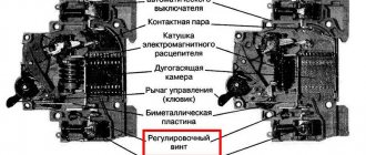
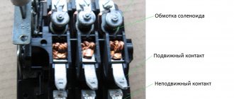
In any machine there are two automatic shut-off elements.
- Electromagnetic release. Designed to trigger when short circuit currents occur. Operated by a current relay.
- Thermal release. Triggers when heated due to overload of the protected area. Based on the operation of a bimetallic contact.
Time-current characteristics are calculated for each separately. They are designated by Latin letters A, B, C, D and are indicated together with the rated current. For the C32 assault rifle this is characteristic “C”.
In order to protect against overload currents, the thermal release is adjusted to certain values. For circuit breaker C32, the time-current characteristic is 1.13-1.45 of the rated current. This means that a device with a rating of 32 Amperes will turn off in an hour at a current of 1.13 × 32A = 36.2 Amperes. If 1.45×32=46 Amperes flow, it will turn off in less than an hour. As the overload increases, the tripping speed will decrease until the electromagnetic release starts to operate.
Electromagnetic release C32 will operate when the current increases 5 times above the rated current - after 0.1 seconds; if the current exceeds the rated current by 10 times, faster than 0.1 seconds.
Types of wires
In the case of the wire brand, the best solution would be the PVS or KG option.
The first type stands for vinyl connecting wire. This product has copper conductors, each of which is protected by insulation and all of which are contained in a white sheath. Such a power wire can withstand voltages up to 450 V, and the insulating material does not burn, which allows the wire in question to be heat-resistant. It is also characterized by high strength and excellent bending resistance. It can even be used in unheated and damp buildings, where it will last 6–10 years, depending on operating conditions. Excellent for connecting electric stoves.
If we talk about wire type KG, then its name stands for flexible cable. Its shell is made of a special type of rubber. In addition, the same sheath protects tinned copper conductors. Between the wires there is a special film that performs a protective function. It must prevent the wires from sticking together due to heat from use.
Typically, a KG wire contains from 1 to 5 cores. As you can understand, the core cross-section determines the power that the cable can withstand. This cable is operated in the temperature range from -40 to +50 degrees. The KG cable can withstand voltages up to 660 V. Typically, this wire has the following designation: KG 3x5+1x4. This means that there are 3-phase conductors with a cross-section of 5 square meters. mm, and one grounding conductor with a cross section of 4 sq. mm.
Regardless of which wire will be selected to connect the electric stove, it should be purchased with a reserve length so that the product can be moved. In addition, the wiring running inside the room and at the entrance to the apartment must be of high quality, which should also be checked before starting the connection.
Rated voltage and load power
Thanks to its modular design, the 32-amp machine can be assembled into blocks of various configurations. In a single-phase circuit it can be single- or double-pole. In three-phase at 380 Volts - three-pole and four-pole. Two-pole ones can also be used in a two-phase circuit, but such networks are rarely used. Protection is usually installed on phase wires. When installed on phase-neutral (2- and 4-pole) switches, they are mechanically connected for simultaneous disconnection.
The 32 A machine is designed for an alternating current voltage of ∼230/400 V. The device is capable of operating for a long time at a given level. When using one pole, the nominal voltage is 230 Volts. When used in a two- or three-phase circuit, when the modules are combined into multi-pole devices - 400 Volts.
Load power is calculated by the formula P=U×I, where P is power, U is network voltage, I is rated current. For a single-phase network of 230 Volts × 32 Amperes, we get 7360 Watts.
A three-pole 32 A circuit breaker is calculated for a three-phase network: 400 Volts × 32 Amperes = 12800 Watts. Since the voltage values are averaged, you need to select a load that is 10% less than the calculations: 7 kW for one phase, 12 kW for three.
Convert Watts (W) to Amps (A).
Converting amperes to kilowatts (single-phase 220V network)
For example, let's take a single-pole circuit breaker with a rated current of 16A.
Those. A current of no more than 16A should flow through the machine. In order to determine the maximum possible power that the machine can withstand, you must use the formula: P = U*I
where: P – power, W (watt);
U – voltage, V (volt);
I – current strength, A (ampere).
We substitute known values into the formula and get the following:
P = 220V*16A = 3520W
The power is obtained in watts. We convert the value into kilowatts, divide 3520W by 1000 and get 3.52kW (kilowatts). Those. the total power of all consumers that will be powered from a machine with a rating of 16A should not exceed 3.52 kW.
Converting kilowatts to amperes (single-phase 220V network)
The power of all consumers must be known:
Washing machine 2400 W, Split system 2.3 kW, microwave oven 750 W. Now we need to convert all the values into one indicator, i.e. convert kW to watts. 1 kW = 1000 W , respectively, Split system 2.3 kW * 1000 = 2300 W. Let's sum up all the values:
2400 W+2300 W+750 W=5450 W
To find the current strength, power 5450W at a network voltage of 220V, we use the power formula P = U*I. Let's transform the formula and get:
I = P/U = 5450W/220V ≈ 24.77A
We see that the rated current of the selected machine must be no less than this value.
Converting amperes to kilowatts (three-phase network 380V)
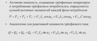
To determine the power consumption in a three-phase network, the following formula is used:
P = √3*U*I
where: P – power, W (watt);
U – voltage, V (volt);
I – current strength, A (ampere);
It is necessary to determine the power that a three-phase circuit breaker with a rated current of 32A can withstand. We substitute the known values into the formula and get:
P = √3*380V*32A ≈ 21061W
We convert watts to kilowatts by dividing 21061W by 1000 and find that the power is approximately 21kW. Those. a three-phase 32A circuit breaker can withstand a load of 21 kW
Converting kilowatts to amperes (three-phase 380V network)
The current of the machine is determined by the following expression:
I = P/(√3*U)
The power of a three-phase consumer is known, which is equal to 5 kW. The power in watts will be 5kW*1000 = 5000W. Determine the current strength:
I = 5000W/(√3*380) ≈ 7.6 A.
We see that for a consumer with a power of 5 kW, a 10 A circuit breaker is suitable.
Source: xn—2-6kchcsatbku0erh.xn--p1ai
Application of S32 assault rifles
A 32 ampere circuit breaker is installed in residential and administrative buildings. Mixed loads, heating and lighting devices, household appliances and electronics are their main areas of application. They do an excellent job protecting household appliances and electronics. They are used as input - installed before meters, or as protection for individual consumers.
It is not recommended to turn on powerful electric motors through C32 devices, even if they are suitable for the load. The time-current characteristic “C” indicates that the protection may falsely operate due to inrush currents.
Video description
How to lay the input cable along overhead lines is shown in the video:
The first is needed to protect the cable from snow melting or falling trees. In these incidents, the fittings break, but the cable remains intact. An insulator is required to protect the jumpers, since due to the rigidity of the SIP, it cannot be directly connected to the panel. To do this, a softer cable is attached to it. Also, when connecting aluminum and copper wires, twisting is prohibited. To do this, all jumpers must be made from terminal boxes, and insulators must be used to protect them.
When tensioning the cable, it should be taken into account that its height above the pedestrian area must be at least 3.5 m, and above the roadway a distance to the ground of 5 m is required. The tension force must be adjusted using a dynamometer. The advantage of air laying is that it requires little resources to connect the cable, and it is also possible to quickly replace the wire.
The disadvantage of this type of entry is that the electrical wiring is exposed and may be subject to damage by trees, weather or other mechanical means. Hanging wires also prevent the access of large vehicles (truck cranes, aerial platforms, fire trucks).
The wire is laid along overhead linesSource samelectrik.ru
Connection diagram
Connection diagram
The wire feeding the switch is connected to a fixed contact, which is usually located on top. The wire to the power receiver is connected at the bottom. To avoid confusion, a simple diagram indicating the contacts is drawn on the case. They are signed with the numbers 1-input, 2-out. In the three-phase version it is similar: even numbers are supply contacts, odd numbers are outputs.
In modern electrical installations, additional devices are used in conjunction with automatic machines: RCD (residual current device), additional contacts, load switches, automatic switching devices. For reliable operation, it is recommended to install devices of the same series from the same manufacturer.
The choice of manufacturers of protective devices is huge. Domestic enterprises can offer reliable equipment, but the range is extremely narrow. The production of additional devices is very rare. Among foreign companies, ABB stands out, having a serious scientific and technical base. Brands such as Legrand, Siemens, GE, Schneider, Electric, Hager also deserve attention. The choice of equipment should be made for a specific project, looking at the range, which is often limited.
Cable calculation
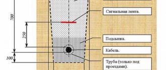
You need to know what cross-section is needed for 15 kW and 380 for input into the house, since with an aluminum and copper core it has different characteristics, and also differs with different connection methods. For open introduction at a voltage of 380 V and a power of 15 kW, a copper conductor with a cross-section of 4 mm² and capable of withstanding a current of 41 A is required, and for an aluminum wire - from 10 mm² and a current of 60 A.
For cables laid in a pipe, copper conductors must have a cross-section of 10 mm², and for aluminum conductors - from 16 mm². The length of the cable depends on the distance of the entry point to the pole, as well as the presence of additional fasteners or supports.
First of all, the wire is connected to the electricity meterSource i.ytimg.com
Why turn off the network when overloaded?
No less dangerous is line overload. When more than rated current flows through the wires, they heat up. This leads to destruction of the cable insulating sheath and subsequent short circuit.
The process of heating the wires takes some time, so to protect the line from overload, protection is used that turns off the power to electrical appliances some time after the problem occurs.
| Information! An increased current when starting an electric motor is normal and lasts less than the response delay of the machine. |
The cause of overload may be the simultaneous switching on of high-power electrical appliances, a malfunction of electrical equipment, or the start of an electric motor, for example, in a vacuum cleaner or air conditioner.
If almost any circuit breaker is tripped by a short circuit, then an incorrectly selected device will turn off the power at the rated current of the line or will not be able to protect the wiring from overheating, so before installation it is necessary to calculate the power of the circuit breaker.
Briefly about the main thing
A cable for laying in the ground for 15 kW of network power must be taken with protection or laid in a pipe. The cross-section of such a wire should be from 10 mm².
Cables are available for overhead and underground installation.
The cable must be routed through the wall in a metal pipe at a slight angle.
The cross-section of the cable directly depends on the method of its entry, as well as the material from which it is made.
For a 15 kW network with a voltage of 380 V, it is necessary to install an additional three-way circuit breaker.
Calculation of cable cross-section method for selecting cable cross-section by current
A simple method for calculating and selecting cable cross-sections.
The question often arises: how to choose a cable for electrical wiring installation. I immediately remember that there are some tables, some cunning methods for calculating the cross-section of cables and wires, and there are also electricians’ reference books. Where can I get all this? And how not to get confused in these tables and formulas.
We will use a simple and practical technique.
First, you should make a reservation: if you do the installation according to the diagram, then you should not have such questions. Since the diagram or project must indicate the cable cross-sections. As they say - “To avoid any bullshit, do everything according to the drawing.
As a matter of fact, let's move on to the methodology for choosing the cross-section of cable cores. As you know, the cable is connected to the machine, that is, the current through the cable will be limited by the current of the machine. The cable could withstand more current, only the machine would work earlier and disconnect the cable from the voltage. Therefore, we will start from the current of the machine.
Now let's see what standard cable cross-sections exist: 1.5; 2.5; 4; 6; 10; 16; 25 is all millimeters squared.
Now let’s see what currents standard machines are designed for: 10A 16A 25A 40A 63A 100A 160A 250A.
You see, whatever the pattern is. The circuit breaker currents and cable cross-sections correspond correctly. And indeed, it is advisable for industry to produce cables with a cross-section suitable for certain machines, and vice versa.
Here is our table for choosing the cross-section of cables and machines.
Table of dependence of cable and machine.
| Power, kWt | Machine | Copper | Aluminum |
| 2,2 | 10 | 1,5 | 2,5 |
| 3,5 | 16 | 2,5 | 4 |
| 5,5 | 25 | 4 | 6 |
| 7 | 32 | 6 | 10 |
| 8,8 | 40 | 10 | 16 |
| 13,8 | 63 | 16 | 25 |
| 17,6 | 80 | 25 | |
| 22 | 100 |
These are the minimum possible values of cable cross-sections, depending on the machines.
Depending on conditions, it may be necessary to increase the cable cross-section.
Using standard tables from the rules, you can determine that a copper cable with conductors with a cross-section of 1.5 mm. sq. will withstand 19A, but where will you get such a machine? 25A will be too much, you will have to take 16A, or even better, take 10A with a margin as in the table above.
Since the resistance of aluminum is greater than that of copper, we take a larger cable cross-section. As can be seen from the table.
Power
For your convenience, I have calculated the power in the table. This is active power at a voltage of 220V on one phase. This makes it easier to select cable cores not only by current, but also by power. At the same time, select the machines based on power.
One more small note - the cross-section of the cable depends on its length and voltage. With a long cable length and low voltage (12-42V), there will be a strong voltage drop, so the cable cross-section should be increased.
Below is a table from the PUE