The process of assembling a switchboard requires special skills and knowledge. The service life of the devices and the reliability of the home’s power supply system depend on the correctness of the chosen scheme and the distribution of consumers. If in old houses with a minimum number of electrical appliances two or three automatic machines were enough, then in modern housing it is necessary to take care of the reliability of the network. Below are basic recommendations on how to assemble a switchboard for an apartment, what circuits and devices should be used, as well as recommendations for eliminating errors.
What is an electrical panel and what is it for?
An electrical panel is a structure consisting of complex modular devices designed to control the power supply network. The main purposes include:
- receiving incoming voltage from the general power supply network of the house;
- analysis of incoming energy parameters and shutdown of the internal network at critical values;
- distribution of consumers into groups by zones, power, purpose;
- direct connection of powerful consumers such as hobs, boiler, washing machines, air conditioning, etc.;
- protection of wiring and household appliances from short circuits and other critical situations;
- ensuring complete safety during operation of the power supply network.
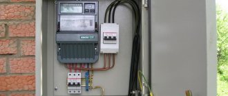
As a rule, they are mounted together with an electricity meter for greater convenience. In new housing stock, where metering devices are located in the corridor, shields are installed at the front door.
Important! It is necessary to provide free access to the panel in order to turn off the machines if necessary.
The electrical panel is the heart of the home electrical system.
We will not be mistaken if we say that the main function of an electrical panel installed at home, in an office, a cafe or any other room is to distribute electricity to consumers and ensure safety when using electrical appliances. Every owner of a residential or business premises at some point is forced to deal with the problem of how to assemble an electrical panel. Long-term uninterrupted operation of the huge number of household appliances that fill any home or office today largely depends on how correctly the electrical panel is assembled.
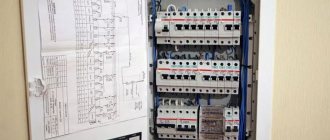
The shield itself is a plastic or metal box in which components (or modules) are placed, each of which performs a specific function. There are so-called internal electrical panels, that is, recessed into the wall, and external ones, located on the wall.
In a private home, the electrical panel is often installed outdoors; in this case, a waterproof design of the device will be required (protection level IP65). Considering the fact that it is unlikely that the electrical panel will be changed annually or even once every five years (as a rule, the device lasts much longer), it would be advisable when choosing a device to give preference to a more expensive, but high-quality panel of a well-known brand with a supply of seats.
Principles of distribution of electricity by groups
Distribution boards, in which several machines are used for the entire apartment, are a thing of the past. The need for a large number of modular devices is explained by convenience and increased safety. If an outlet breaks down in one of the rooms, you can turn off one circuit breaker, and the rest of the network will continue to operate as normal. The basic rules for assigning groups are described below.
- Powerful consumers . All devices with a power of more than 2 kW are connected separately or combined into small groups. For each of them, a separate line is drawn with an individual circuit breaker. As a rule, the cable cross-section and machine rating are chosen with a small margin. For most cases, a copper cable VVGng or NYM with a cross-section of 2.5 mm2, as well as a 16A automatic, is suitable.
- Heavy-duty devices require separate lines. Such devices may include instantaneous water heaters from 5.5 kW and hobs, the power of which starts from 6.5 to 9.5 kW. To connect them, use a cable with a cross-section of 4 or 6 mm2, as well as 25A and 32A circuit breakers.
- Outlet groups are combined by room, and several groups are also created for one large room. The common line runs from the panel to the junction box, where the cable branches. A VVGng or NYM cable with a cross section of 2.5 mm2 and a 16A circuit breaker are sufficient.
- Lighting is distributed among the rooms . For example, different groups for the bathroom, bedroom, balcony. Lines with a 1.5 mm2 wire are protected by 10A circuit breakers.
Reference! The rating of the machine directly depends on the cross-section of the cable, as well as the power of the consumers.
Where to start?
Every experienced electrician will confirm that it is much easier to begin work on installing an electrical panel and wiring, having before your eyes a floor plan indicating the intended placement of household appliances, lighting fixtures, as well as sockets and junction boxes. Having decided on the number and power of consumers, it is necessary to draw up a diagram of the electrical panel itself. A single line diagram might look like this:
In this diagram, all consumers are divided into 20 groups, for each of which the following is indicated:
- wire grade and core cross-section, mm²;
- power;
- current consumption;
- type of circuit breaker indicating the rated current.
For the uninitiated, such a diagram looks quite complicated, so you can use a simplified schematic representation of the location of the electrical panel components.
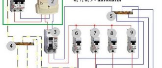
For greater clarity, the electrical panel diagram can be depicted as follows:
Or even like this:
Where
- 1 - introductory AB;
- 2 - counter;
- 3 - zero bus;
- 4 - grounding bus;
- 5–10 — AV consumers.
Having such a diagram in hand, it is much easier to figure out how to properly assemble an electrical panel.
Requirements for distribution panels
There are special requirements for electrical equipment, since it is responsible for the safe operation of household appliances. The following must be required:
- Availability of a technical passport with a description of consumers and rated current.
- Developed connection diagram.
- Marking of wires with the designation of line devices.
- Grounding the shield and all connected devices.
- If the shield is metal, the structure and doors must be grounded, and the housing coating must be dielectric.
- The presence of free terminals on the neutral and ground wire buses.
- The shield is made of non-flammable material.
Reference! All shields must comply with the rules of GOST 51778-2001 and PUE.
Drawing up a diagram
Modern power supply systems involve the use of a three-wire cable, where one wire is a phase, and the rest are ground and zero. Given the growing power of devices, it is also necessary to divide them into groups, which allows to increase the service life of the wiring. Guided by these principles, we proceed to drawing up a diagram of the shield.
Advice! It is better to entrust the design of the panel and electrical wiring of the apartment to a professional so as not to miss important details. Otherwise, you will have to redo the repair.
It is mandatory to install a protection device on the input cable, which will protect the internal network from overvoltage. Then they install a voltage relay to control surges in the network, after which they proceed to the installation of groups and individual lines. It is worth noting that for powerful devices, in addition to switches, additional RCDs or differential circuit breakers are used. Such organization of the home electrical network is not only safe, but also convenient. If necessary, you can turn off the machine and turn off the washing machine. You can also turn off the RCD and de-energize all consumers included in the global group.
Briefly about the main thing
Connecting a private house to a 3-phase network makes it possible to reduce the load on a phase, use conductors of a smaller cross-section and connect both 1-phase and 3-phase equipment. The electrical panel must provide protection not only for electrical appliances and conductors, but also for the people in the house. The main feature of assembling a 3-phase electrical panel for 15 kilowatts is to correctly distribute the load and prevent phase imbalance.
The 3-phase electrical panel should include the following devices:
- Electrical cabinet
- Counter.
- Introductory machine.
- RCD.
- Circuit breakers for groups.
- Voltage relay.
- Current and voltage meters.
The panel can be assembled in several variations - only on automatic machines, with one RCD, with the load distributed over 2 RCDs, with an RCD in each phase and the number of RCDs more than 3 for a powerful device or group. Each scheme has its own pros, cons and application features. The shield must be installed in accordance with special rules and proper load distribution across phases.
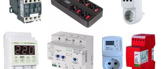
Electrical Panel Components
The distribution board consists of many devices. For reliable operation of the home electrical network and protection of household appliances, it is necessary to use circuit breakers, RCDs and differential circuit breakers, voltage control relays, buses and much more.
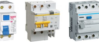
Circuit breakers
Devices for automatic protection of the line that is connected to them. They interrupt the power supply if the current in the line is significantly higher than the rated value. Protection against cable heating is also provided.
RCD and diffautomatic devices
The residual current device (RCD) switches off the load if leakage currents appear. First of all, people can suffer from them. The leak also negatively affects the wiring, causing the wires to heat up and catch fire.
Differential circuit breaker - protects against short circuits, overloads, and current leaks. It is often used instead of a combination of a pair of RCDs and a conventional machine. The main advantage is short circuit protection.
Voltage control relay
The device is used to measure the incoming voltage and maintain a given value. In case of sudden surges in the network, the device turns off the power supply. The electrical circuit is closed only after the indicator and time delay have been restored. The main purpose is to protect electrical appliances from power surges.
Grounding and grounding buses
Busbars for grounding and zero are used for ease of installation, as well as compliance of the shield with all the rules of GOST and PUE. The number of DIN rails depends on the number of machines and other modules, so it is necessary to draw up an installation diagram in advance.
Comb tire
It is used instead of cable jumpers, which were previously made by electricians themselves. The comb looks like a solid plate with protruding teeth and is designed to connect machines standing in the same row.
Other equipment
As additional equipment in the distribution panel, modular contactors, load switches, DIN rail sockets, timers and much more are used. Other devices increase the convenience of managing the power supply network.
The final stage
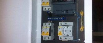
The shield is installed in its place after all dirty repair work is completed. The panel body is mounted in a niche, the DIN rails with the assembled modular equipment are fastened with self-tapping screws. The working (N) and protective (PE) zero buses are fixed. Phase and neutral wires are arranged in separate bundles and laid on opposite sides of the shield. The force with which the connections are clamped is 0.8 Nm.
Before starting commissioning work, you should make sure that all sockets, junction boxes, and switches are assembled. All consumer groups should be signed on the external panel of the electrical panel. After about a month of work, all connections of the shield should be tightened.
How to calculate the number of places in an electrical panel?
All equipment for the switchboard is standardized and installed on a special DIN rail. The unit of measurement for space is considered to be a “module” with a width of 17.5 mm. All panels are sold depending on the amount of space: for 8, 12, 24, 36 modules.
Reference! To calculate the number of seats, it is necessary to take into account all devices, including RCDs, automatic machines, voltage relays, and differential automatic devices.
Circuit breakers have a standard width of 17.5 mm. The remaining devices have the following characteristics:
- two-pole circuit breaker - 2 modules and 35 mm;
- three-pole circuit breaker - 3 modules, 52.5 mm;
- single-phase RCD - 2 modules and 35 mm;
- three-phase RCD - 4 modules and 70 mm;
- diffautomatic - 2 modules and 35 mm;
- voltage relay - 3 modules, 52.5 mm;
- DIN rail socket - 3 modules, 52.5 mm;
- terminals for DIN rail - 1 module 17.5 mm.
Electrical panel assembly
When the panel diagram has been created and the electrical wires have been laid around the apartment, we proceed to assembling the panel. If desired, you can order a prepared shield, which all that remains is to install and connect the input cable.
Advice ! Indoor renovation is a messy process, so it is recommended to assemble the panel in another place, and then install the finished equipment in place.
Marking and installing DIN rails
First, markings are made of where the modules will be located and how long the slats are needed. During the fitting process, they also take into account the distance between the rows, if there are several of them, as well as the distance between the zero and ground buses. When the marking is ready, the slats are installed in the required places.
Reference! Most panels are standardized, so the placement of the slats is limited by the manufacturers.
Installation and switching of modular devices
At the stage of installation of modular devices, automatic machines and additional devices are installed on a DIN rail. They are also connected to each other. First of all, they install an input circuit breaker, then voltage relays, RCDs and differential circuit breakers, which are located in front of conventional switches.
Advice! Install the modules closer to the center, leaving space on the sides for neat cable management.
Organization of cable entry into the electrical panel
At the stage of cable entry, it is necessary to make holes in the shield. As a rule, all insertion points are provided by the manufacturer, so it is enough to squeeze out the plastic. On one side, a general network cable is installed, which is connected to the input circuit breaker, and on the other, internal network wires.
We run cables into the electrical panel
Having a special cable entry with a removable cover can eliminate problems with wiring cables into the panel. On high-quality panels, such an input is usually provided; low-quality ones are better not to be considered at all. If the electrical panel is installed outside, there are usually no problems with cabling. If the shield is hidden in a niche, there may be nuances: getting to the inlet hole in this case can be quite difficult, so the electrician needs to be patient and persevering.
The design of the cable entry of the electrical panel, as a rule, provides for perforated holes, which are brought to the required size by simply removing excess jumpers. The cables are fed into the shield through a corrugated pipe, the standard size of which is 16 or 20 mm; accordingly, the holes should be made of this size.
Often the electrician is hampered by the mobility of the wires inside the corrugated tube. To fix the wires and make them stationary, some use alabaster, which is applied to the input hole from the side of the gate. Let us immediately make a reservation that this method of fixation is not convenient and aesthetically pleasing. It is much more efficient to secure the wires using special removable plugs or gland plates.
To avoid future confusion with wires, you should immediately label them. The input cable is usually connected in the upper left corner - where the input machine is usually installed.
Basic installation mistakes
- A flexible multi-core cable without sleeves at the ends is a weak point in electricity. Over time, the quality of the contact weakens, the connection begins to heat up and cause problems.
- The cable insulation gets into the terminal, and at times of high loads it heats up and melts.
- Wires of different cross-sections per machine - this inevitably leads to poor contact, overheating of the wire and even a fire.
- Soldering the ends is an old and not reliable enough way to connect wires. Only suitable ferrules are used for connection.
Be sure to crimp stranded wire or use rigid solid cable.
6 Connecting cables - entry and termination inside the panel
Correct cable entry greatly simplifies installation and allows for optimal organization of the internal space. You should buy shields that have technological holes for entry, otherwise you will have to cut or drill them. Good shields have plugs that we remove and install the cable. We connect it to the input machine and secure it with a plastic clamp. We mark all cables at once.
Surface insulation on the input is not needed, so carefully, so as not to damage the insulation of the conductors, remove it. It is more convenient to work with individual wires than with a rigid cable. We distribute all the wiring in the panel in bundles: separately phase (L), zero working (N) and protective zero (PE). We strive to ensure that they overlap as little as possible. We pre-mark the ends and tighten them with clamps.
Connecting cables to the panel
When bringing the cable inside the shield, we leave it a length that is twice the height. This is done like this: stretch the cable to the connection point, stretch it again to the inlet hole and cut it off. This is not superfluous at all: the wiring follows its own trajectory, and not the shortest path. When you have to pull them to reach their destination or build them up, this is bad. So it’s not worth saving a few ten centimeters.