The presence of an electrical panel in a residential building or in a country house allows you to solve two problems at once: distribute the load throughout the room and protect devices in case of accidents.
It is advisable that competent organizations deal with this issue, but if you have some skills in handling electricity, then installing an electrical panel and connecting it will not be difficult. As a rule, the main machine and the meter are connected by the electricity supply organization, but after the meter you can do the wiring yourself, only before starting up you will have to invite representatives of this organization so that they check everything and measure everything. Naturally, this will cost some money, but still, it will be much cheaper than if the wiring and installation of the electrical panel were carried out by people from the appropriate company. The only condition is knowledge of the norms and rules for carrying out such work. After all, the panel, sockets and switches are installed at a certain height.
Preparing the site and installing the shield
It is better to make a niche for the electrical panel at a height of 1.5-1.8 meters from the floor.
And it is better to place it near the entrance to the apartment. Before you start, it is better to find out the thickness of the wall in which you are going to make a niche for mounting the panel; if it is not sufficient for installation, it is better to hang an external panel. If the walls are concrete, be patient and use special grinder discs for concrete. Or make a false wall of plasterboard in front of the concrete one; it will be convenient to hide the incoming wires under it. At this stage I was lucky, the walls of my house are made of Crimean shell, a very pliable material. After the future installation site was ready, I began assembling the shield. Replace the zero bus and ground bus.
It was also necessary to ground the door and the panel itself (requirements of the energy company), for this I connected a wire to them as shown in the photo.
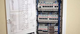
Having determined the locations for all the circuit breakers, I installed them on the rail. I placed the machines of the “strongest” consumer groups closer to the main 32 A machine.
Next it was necessary to make jumpers between them. I made the jumpers from the same copper wire with a cross-section of 4 mm as shown in the figure. But it is better to use a special tire.
All that remained was to put the shield in place.
Through special holes in the shield, I inserted into it all the groups of wires, marked in advance (if you do not mark in advance which group each wire goes to, then confusion may begin)
And he began to insert wires into circuit breakers and differential circuit breakers. Using a mounting knife, I cut off the outer white braiding from the cable and pulled the wires to the connection points by color.
Until the new meter fell into place, I supplied power to the panel from the old meter. As the new group was connected, I supplied power to it.
If you do it correctly, you don’t have enough money, below I showed a cheaper, but also reliable scheme.
Installation and connection of electrical devices
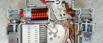
All modern automatic machines and RCDs have a special unified mounting location, which is absolutely compatible with the mounting DIN rail located inside the panel, no matter what its design. A special latch is mounted on the back of the machine or RCD, which can be bent using a screwdriver. Everything is very simple: take a screwdriver and insert it into the hole, after which you need to forcefully pull the latch. The device is installed on the bar and the latch is released. As a result, the machine or RCD is securely held on the DIN rail. At the same time, you can hear a characteristic click.
After installing all electrical devices in their place, proceed directly to the connection. First, connect all the wires that supply power to the corresponding groups of objects. Each wire should have a mark. For example, when laying out wires, you should write on the wires: kitchen, bath, toilet, hallway, bedroom, hall, balcony, etc. If the inscriptions are made in a timely manner, immediately after wiring, then there should be no problems with the connection. After the wires are connected to the lower terminals of each machine, they begin to connect protective devices and supply voltage to all machines. In this case, all machines must be in the off position (“off”).
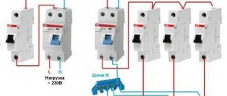
The phase wire is connected to the upper terminals of all machines through a protective device, and the neutral wire is connected to a separate neutral terminal. Modern requirements predetermine the installation of a two-pole input circuit breaker.
The RCD connection diagram looks like this, as shown in the photo.
How to install an RCD on a DIN rail is shown in the video.
How to properly connect an RCD
After everything is connected, you need to check everything and only then, one by one, the machines begin to turn on. If you have certain skills, then it is better to check all the wiring using the device for short circuits. After turning on the machine, it is advisable to check the presence of voltage in the room it protects, if there is no short circuit. If the RCD trips after switching on, it means there is a leak or an indirect short circuit somewhere. In the event of an obvious short circuit, the circuit breaker that was turned on should be triggered. As a rule, group circuit breakers are designed for a lower operating current, which means a lower short-circuit current. This approach ensures selectivity of protection.
How to properly connect an RCD: video.
How to properly connect an RCD
In the process of independently connecting all the elements located in the panel, you should know that the meter and the input machine are subject to sealing. Modern electrical panels have everything covered. Unfortunately, not every model is equipped with a separate box where an introductory machine is installed. If this is not provided for, then the organization will either refuse to seal and write an order, or seal the entire shield, without the right to access it in the future.
In the following video you can see what types of machines there are and how they differ from one another, except for the manufacturer.
Circuit breakers - polarity and connection diagrams
Electrical appliances installed inside the panel are connected to each other using jumpers made of ordinary insulating wire or using a factory-made comb. What it is like to connect circuit breakers with wires can be found in the photo.
Jumpers are manufactured:
- From conductors of the appropriate length, in which the insulation is removed at both ends, and the ends of the conductors are bent with an arc. Two conductors are inserted into each terminal and only one into the outermost circuit breaker, after which they are securely tightened with screws.
- From one long conductor, from which the insulation is removed after a certain distance. After this, using pliers and pliers, the conductor is bent in arcs. The bare ends of the arcs are inserted into the terminals and tightened with screws.
Almost all electricians do this, and if you show care and diligence, the contacts will turn out good. At the same time, there is an alternative option when special tires (combs) are used instead of conductors. How to connect all the machines using a bus can be seen in the video.
Connecting machines using a bus
The phase wire is connected to one of the machines, to the top terminal, where they are connected using a wire or comb. If a wire was used for connection, then power is supplied either to the far right or to the far left machine, where only one conductor is pressed. If you connect the power to other machines, the connection will not be as reliable, since the terminals of these machines already have two conductors and the third conductor is simply superfluous.
If everything is done correctly, we can assume that the shield is ready for use.
Assembly Rules
There are certain rules that should be followed when assembling an electrical panel:
- all wires inside the panel must be of the same cross-section as the input wire;
- any module must have an entrance at the top, an exit at the bottom;
- if installation is carried out using PV3 stranded wire, it is necessary to use NShVI lugs.
The sequence of steps for an electrician performing the assembly may look like this:
- preliminary arrangement of modules on DIN rails in accordance with the existing diagram;
- fixing modules on DIN rails using special fasteners;
- installation of comb buses, with the help of which voltage from the AV input is supplied to the remaining modules;
- distributing the phase to its destination from the lower terminals of the modules using wires with lugs;
- installation of the neutral wire. All wires are mounted behind the DIN rail;
- tightening all connections using a screwdriver;
- supplying voltage to the input machine and checking the functionality of the modules;
- checking the presence of voltage at the inputs and outputs of the modules using a multimeter.
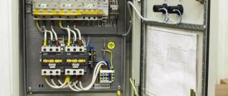
Electrical panel assembly
Experienced electricians assemble electrical panels more accurately and faster than beginners. An experienced assembler is characterized by tight wiring installation, right angles and clarity of the resulting diagram. High-quality assembly requires practical and theoretical knowledge and the ability to use equipment. Therefore, it is important to understand how the switchboard is assembled.
DIN rails
DIN rails are a metal profile designed for quick and convenient installation of modular devices, usually automatic machines or RCDs. The rail is made of iron. If necessary, it can be shortened to the desired size with a grinder.
The rail is attached to the shield with self-tapping screws. Its length is selected based on the number and width of devices that need to be installed on it. However, it is better to leave some margin in size and take a DIN rail 5-10 cm larger. This solution will be useful when upgrading the shield in the future or adding new devices. For example, additional group circuit breakers.
Installation and connection of modular devices
Automatic devices, RCDs and other equipment are installed in the switchboard using DIN rails. For this purpose, a latch is provided on each of the devices in their rear part.
To install a modular device, you need to hook it onto a DIN rail. There is a special “tooth” at the top of the device. There is a latch at the bottom. The modular device is attached (hung) to the upper tooth. Then a slight hand force is applied to the lower part until a characteristic click is heard. Here it is important to understand where the mounted device is top and bottom.
A screwdriver is required for removal. With its help you need to pull back the lower tooth of the mounting ear. It can be found on the back of any modern circuit breaker.
Connecting modular devices is usually done using screw terminals. A little less often, in low-current equipment, WAGO type clamps are used, into which it is enough to insert a wire core terminated with a sleeve.
Cable entry for panel
If the switchboard is to be used in an apartment, then it is enough to insert the wires through one of its holes. It is important to ensure that the wiring insulation does not rub against the metal edges of the hole, which should be smooth and free of metal burrs.
If the operating conditions of the shield are more severe (dust, drops of water), then it is necessary to take care of the tightness of the input and output cables. For this purpose, sealed inputs are used. They come with minimal basic protection. Such bushings are cheap and protect switchboard equipment from large dust. But there are also more expensive models that can ensure complete sealing of the wire entry point and protect panel devices from direct jets of water.
Place for installing an electrical panel
Proper installation will save maintenance personnel from a lot of problems in the future. Therefore, when choosing a place for installation, you should be guided by a number of simple rules:
- The electrical panel must be accessible; its door must be easily and unhindered by qualified personnel. Helps with urgent emergency transfers or repairs.
- The shield should not be placed in places where flooding is possible. No sealed input will save the inside of the shield from a long stay under water. This also applies to dachas with spring floods.
- If the shield is not sealed, then it can only be installed in dry rooms. Rain and moisture from the air can penetrate inside and lead to corrosion.
- Avoid flammable or explosive vapors, as well as flour or wood dust. Contactors, magnetic starters and relays installed in switchboards can spark during operation. This factor can lead to fire or explosion.
Additional Information. According to the rules, a “lightning bolt” type warning sign is located on the door of the electrical panel. It is designed in the form of a pictogram with a black zigzag in a yellow triangle. For household panels, the sign is issued in the form of a sticker. Its purpose is to prevent children and untrained people from electric shock. Do not neglect the installation of this sign.
Stripping cables
If there are few wires, you can use any sharp knife, even a kitchen or stationery knife, to remove the insulation. Here it is important to cut only the insulating layer and not damage the current-carrying conductors. This skill comes with experience.
If there is a lot of wiring, then it is more rational to buy a specialized knife for cutting cables. It allows you to perform electrical installation work faster and better, with less physical effort and the risk of injury (cutting yourself).
Connecting group consumers
For clarity and convenience of connecting individual consumers, they are usually divided into groups. This approach allows you to assemble a horizontal ruler from difavtomats. Usually it is located at the bottom of the shield. Each machine is marked with a separate tag indicating its purpose. For example, “light in the living room” or “washing machine.”
Tags are written by hand on small sheets of paper or purchased at an electrical store. The second option is more convenient, since the store tag for the electrical panel has an adhesive layer and is easier to attach next to the corresponding machine. Regardless of the designation method, it is important to ensure that the indicated inscriptions are legible to other people.
Assembly Requirements
Recognition of phase and zero in a wire
Work carried out on electrical devices and wiring is classified as particularly dangerous. Therefore, assembling an electrical panel requires compliance with certain requirements:
- filling with elements taking into account the recommendations given in technical documents; exceeding the number of devices is prohibited;
- the presence of an electrical protection sign is mandatory; the permissible voltage of the device is indicated here;
- the materials from which the electrical panel and its parts are assembled must not conduct current or ignite;
- Marking is required on the cables; special tags are used to mark individual groups of elements;
- the terminals are connected to the wires one at a time, the tires are distinguished by color (black - phase, blue - zero);
- if several circuit breakers are used, the connection between them is made using a special bus conductor;
- Grounding is mandatory for the body and cover;
- If a private house is built of wood, internal wiring cannot be laid, so special pipes and ducts are used.
Maintenance of electrical panels
Even a correctly assembled and approved electrical panel requires maintenance. The frequency of these measures is determined based on operating conditions, requirements for uninterrupted operation and complexity of the equipment.
The main maintenance activities for the switchboard include the following:
- visual inspection of wires under load;
- listening to the live panel for crackling or unnatural buzzing sounds;
- tightening screw connections and terminal blocks (with stress relief);
- cleaning switchboard equipment from dust and other pollutants;
- checking the presence of tags on the wires and their compliance with the electrical diagram;
- measuring the temperature of individual devices and contacts;
- control of the presence of seals on measuring instruments (in the case of commercial accounting).
Without electrical panels it is impossible to build complex electrical networks. You can’t do without them in a small one-room apartment. With their help, protection and automation devices (RCDs, current and voltage relays) are assembled compactly and in one place. Thanks to this, electricians have convenient access to key power control and distribution units.
The assembly of electrical panels begins with design, drawings and diagrams. This takes into account the dimensions of the devices included in the system. At the same stage, the location of the equipment is also considered, because high humidity and dust can damage the internal electrical devices of the panel.
Recommendations for assembling an electrical panel in an apartment
learn the rules
Finally, instead of summing up, general recommendations for assembling an electrical panel will be given:
- the shield should be slightly larger so that in the future, if there is a need for additional machines, it does not have to be changed;
- It is not recommended to combine several household appliances with different purposes under one residual current device, since it may happen that the computer in the living room turns off, and the hairdryer in the bathroom turns off. Therefore, there are zones geographically: the kitchen is separate, the bathroom with toilet is separate, etc.;
- It is recommended to install a residual current device after the machine according to the diagram, and it should be one step higher than the rated current value. For example, the automatic/RCD pair should be 16A/25A, since the RCD does not respond to a short circuit. The machine must be responsible for this, so it is better to take an RCD with a higher rating to eliminate the possibility of its burnout. You can also set equal values, there will be no error here;
- Ideally, an RCD would be installed in each zone after the machine, but due to the high cost of the former, several machines have to be installed on one RCD;
- RCDs and differential circuit breakers are not recommended to be placed on sockets where the computer will be turned on, since they can cause false operation of the protection, especially if the response threshold is incorrectly calculated;
- electronic or mechanical RCD - many buyers face this question. The most ideal option would be the latter, due to its reliability and independence from electricity;
- RCDs and automatic devices must be installed correctly. If it protects several circuit breakers and stands in front of them according to the diagram, this is already a violation, and in front of the RCD there is an introductory circuit breaker, or even several. The fact is that this is prohibited according to energy supervision rules. According to the requirements of this organization, an automatic circuit breaker must be installed on the incoming cable, followed by a meter and only then an RCD. By the way, you can install a differential machine in front of the meter.
What electrical appliances should be in the panel
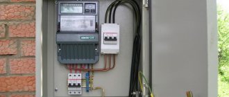
Depending on whether it is an apartment or a private house, electrical panels can be installed differently, depending on where the meter and input machine are installed. Nowadays, the meter and the input machine, if you take a private house, are installed outside, in a place convenient for control. The panel is installed inside the house, where it is convenient to control electric lighting and operating electrical appliances. Several decades ago, both the meter and protective plugs were installed in the house, which was extremely inconvenient for regulatory organizations. They had to enter private houses, which the owners did not really like. Now that the meter is located on the street, it is convenient to both control and reduce readings.
Unfortunately, this option is not always and everywhere possible. In this case, the meter is installed in the apartment in the panel where the circuit breakers are located. Therefore, when installing the panel, it is necessary to take into account the dimensions of the meter and the number of switches.
In apartment buildings, as a rule, meters and input machines are located on staircase landings, in special electrical panels, where several meters are placed at once, serving several apartments. At the same time, no shields are provided in the apartment, especially if the apartment is not of a modern layout. In case of renovation in an apartment, an electrical panel is simply necessary, as this will allow you to share the power supply to almost all rooms, which makes them independent. This is especially true in the event of an accident, when it is possible to provide this line with a separate automatic machine and carry out repair work. At the same time, in the remaining rooms all electrical appliances will function as before.
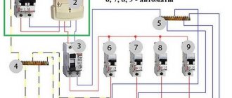
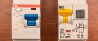
Jokes with electricity always end in failure, therefore, the issue of safety should come first. There is such a device as an RCD - a residual current device (photo above No. 3), which must be installed in front of the machines that distribute the load in the apartment. This device protects the line even if such leaks are minimal, thereby minimizing electric shock. The RCD is turned on as follows: the phase is connected to the inputs of the machines, and the neutral wire is connected to the neutral common wire. The machines also have built-in protection against overload and short circuits.
Another interesting device that you sometimes cannot do without is a stabilizer. It's no secret that the quality of our power supply is disgusting: the voltage constantly “jumps” from 160 V to 280 V, which negatively affects the operation of some electrical appliances, the operation of which is controlled by microprocessors. In this regard, equipment such as computers, washing machines, refrigerators, audio and video systems require stable voltage. If something happens, their repair can be expensive, therefore, it is better to play it safe and purchase a stabilizer not for the entire apartment, but only for critical household appliances. Naturally, you should think about this in advance and combine critical power outlets into one group.
The stabilizer can be installed on one or several groups if you turn it on in front of the machines. At the same time, you need to carefully calculate the required power and take care of a power reserve of at least 20% so that the stabilizer does not overheat. At the same time, you should take into account the fact that the dimensions of the stabilizer will not allow it to be placed in the shield, which means that the stabilizer will have to be installed separately and this must be taken care of in advance.
There are 2 buses in the electrical panel: a grounding bus and a grounding bus. All wires connected to the grounding of instruments and devices are connected to the grounding bus. The wire from the RCD (zero) is connected to the grounding bus. The neutral line is always designated by the letter “N” and when wiring, all white or green-yellow wires are connected to it, and the phase wire is always red or brown. That is why it is advisable to use multi-colored wires for wiring, so that later you do not have to call out each wire. This is especially true for those who are doing this for the first time: you can screw things up that then specialists will have to figure out for several days.
All machines in the panel are connected in parallel, or rather, the upper terminals where the phase is supplied. The lower terminals are each connected to a separate line, which feeds separate rooms.
Option of DIN rails in the panel housing
RCDs and automatic devices are mounted on a special DIN rail using latches, so there should be no problems with installing such devices.
Connecting comb for machines in electrical panels
How to assemble an electrical panel with your own hands
Consumer calculations
A complete list of consumers is compiled. To do this, you do not need to take into account devices like a fan or a table lamp, but write down and number each wire connected to the panel. Sockets must be recorded separately, lighting - separately. High-power appliances (boilers, washing machines, air conditioners, electric stoves) require wiring protection from overload, so they are connected not through distribution boxes, but directly to the panel.
The list of consumers for a three-room apartment usually looks like this:
sockets:
- bedroom;
- living room;
- children's;
- kitchen;
- bathroom;
- entrance hall and corridor.
- Washing machine;
- boiler;
- air conditioner;
- electric stove;
- lighting:
- bedroom;
- living room;
- children's;
- kitchen, bathroom;
- hallway, corridor.
All consumers are divided into groups (circuits) in accordance with power consumption: sockets for household appliances in one room such as an iron, sconce, TV and others can be combined into one group (sockets in one room - one group, in another - another), lighting - to the next one, also by room. Each group has its own circuit breaker (or just a circuit breaker) on the panel, and for high-power appliances - washing machine, boiler, electric stove, air conditioner - there is one separately for each. Machines may also be called fuses or bags.
Next, the list is converted into a table where the ratings of the machines and RCDs are entered.
Schemes for several consumers
Power supply schemes depend on the categories of electrical consumers and their significance. Groups of electrical consumers are distributed by floor, by purpose of the building, by the number of rooms, etc. Usually they separate living rooms and outbuildings, basements and garages, as well as street lighting. If there are many consumers, then not on each individual line, in addition to the main RCD, separate RCDs of lower power should be installed. The kitchen and bathroom must be protected with protective devices according to a separate scheme.
If it is planned to install consumers with a power of up to 2.5 kW, then it is desirable to install separate protection. Household appliances such as a microwave, electric kettle and hair dryer have similar power.
At the stage of developing a power supply scheme for electrical consumers, first of all you should think not about savings, but about safety. All electrical appliances are purchased only from well-known companies, and they cost a lot of money.
Connection diagrams for RCDs in a single-phase network
The industry produces residual current devices designed to operate in single-phase or three-phase networks. Single-phase devices have 2 poles, three-phase devices have 4. Unlike circuit breakers, neutral conductors must be connected to disconnecting devices in addition to phase wires. The terminals to which the neutral conductors are connected are designated by the Latin letter N.
To protect people from electric shock, RCDs that respond to leakage currents of 30 mA are most often used. In damp rooms, basements, and children's rooms, devices set to 10 mA are used. Switching devices designed to prevent fires have an operating threshold of 100 mA and higher.
In addition to the response threshold, the protective device is characterized by its rated switching capacity. This term refers to the maximum current that the disconnecting device can withstand for an unlimited amount of time.
An important condition for the reliable functioning of protection against leakage currents is the grounding of the metal casings of electrical devices. TN grounding can be done via a separate wire or through the ground pin of the mains socket.
In practice, two methods are used to connect residual current devices into an electrical circuit:
- RCD connection diagram with individual protection;
- group consumer protection scheme.
The first switching method is most often used to protect powerful electricity consumers. It can be used for electric stoves, washing machines, air conditioners, electric heating boilers or water heaters.
Individual protection involves the simultaneous connection of an RCD and a circuit breaker; the circuit represents a serial connection of two protective devices. They can be placed in a separate box in close proximity to the electrical receiver. The selection of the disconnecting device is carried out according to the rated and differential current. It will be better if the rated breaking capacity of the protective device is one step higher than the rating of the circuit breaker.
In group protection, a group of circuit breakers that supply different loads is connected to the RCD. In this case, the switches are connected to the output of the leakage current protection device. Connecting an RCD in a group circuit reduces costs and saves space in distribution boards.
In a single-phase network, connecting one RCD for several consumers requires calculating the rated current of the protective device. Its load capacity must be equal to or greater than the sum of the ratings of the connected circuit breakers. The choice of the differential protection response threshold is determined by its purpose and the hazard category of the premises. The protective device can be connected in the panel on the staircase or in the distribution panel inside the apartment.
The connection diagram for RCDs and circuit breakers in an apartment, individual or group, must comply with the requirements of the PUE (Electrical Installation Rules). The rules clearly require that electrical installations protected by RCDs be grounded. Failure to comply with this condition is a serious violation and may lead to negative consequences.
How do machine guns protect?
Automatic switches (circuit breakers) are selected according to their operating current, which is determined by the total current consumption of devices of the corresponding group. To determine the current, you need to add up all the powers of electrical household appliances connected to a given line and divide by 220V. The circuit breaker is selected with some margin so that it does not turn off due to overload. For example, with a total power of 6.6 kW (6600W), if divided by 220V, you get 30A.
Machines are produced with the following current ratings: 6A, 10A, 16A, 20A, 25A, 32A, 40A, 50A and 63A. Based on the calculations, a machine with an operating current of 32A is more suitable, and that is what needs to be installed.
Types of shields for a private home
Electrical panel housing for outdoor installation
Electrical panels are designed for safe supply and distribution of electricity throughout a private home. Depending on their functional purpose they are divided into the following types:
- Input devices installed at the point where the power cable is connected.
- Boxes for installing a remote electric meter.
- Distribution boards mounted directly in the house and designed for distributing internal supply lines, as well as protecting them.
They are practically no different from the same products installed in apartments in urban buildings. The difference usually manifests itself only in the fact that significantly more samples of control, protective and distribution equipment are installed in them. In private households, it is also possible to make a separate panel designed specifically for servicing lighting lines.
Separation of consumers into groups
The electrical panel has a general input circuit breaker. From it, the wires disperse to group circuit breakers, of which there are up to several dozen in a three-room apartment.
Group circuit breakers are designed to divide consumers into separate, independent circuits. For example, sockets in the living room are connected through the QF3 machine. From QF4 - bathroom. And QF5 is apartment lighting. For a private home, separate protection of lighting circuits on the street or in the garage can be performed in a similar way.
Dividing consumers into groups makes it possible to make apartment protection selective. If there is a short circuit in the living room outlet, only the electrical appliances in that room will turn off. The lighting and voltage in the sockets of other rooms will remain intact.
Dimensions and types of electrical panels
Having calculated the number of components and drawn a diagram of the electrical panel, you need to take care of where all these elements will be installed. It's time to buy a cabinet that will fit all the necessary electrical equipment. First of all, we determine the exact location of the electrical panel. The type of cabinet will depend on the location. For example, if the shield will be installed outdoors, you will need a moisture-proof cabinet; if indoors, you can get by with a regular one.
The following types of electrical panels are distinguished:
- plastic and metal;
- wall-mounted and built-in;
- collapsible and solid;
- with a large and small number of places;
- with a solid and transparent door;
- with and without locking mechanisms.
Also, cabinets for household electrical panels differ in size and shape. The cabinet should be selected according to the location and amount of electrical filling, but if you have a choice, take a large panel. A larger panel is easier to work with and will provide extra space in case you ever decide to upgrade your electrical system.
The size of the panel is determined not only by the dimensions of the cabinet itself, but also by the number of spaces for single-pole circuit breakers with a thickness of 12 mm. Consider the fact that your circuit will contain not only single-pole, but also double-pole circuit breakers, which are twice as thick. In general, in order to correctly calculate the number of required spaces in a future cabinet, you will need to know the dimensions of all the machines used in the circuit. But this is not particularly difficult, since most often their sizes are standard.
Let's give an example in which you can see how many spaces in the panel a particular module will take up.
- A single-pole machine will take 1 place.
- A two-pole machine will take up 2 spaces.
- Three-pole machine - 3 places.
- Single-phase RCD – 2 places.
- Three-phase RCD – 4 places.
- Single-phase automatic circuit breaker – 2 places.
- Tire – 1st place.
- Modular socket – 3 places.
- Voltage relay – 3 places.
- Modular electric meter – from 6 to 8 places.
Calculation of panel dimensions and DIN rail length
With the advent of globalization, electrical equipment manufacturers were forced to standardize the dimensions of their products. All automatic devices, RCDs and modular devices have standardized dimensions.
This approach allows you to easily calculate its dimensions at the shield development stage. For example, a standard circuit breaker is 17.5 mm wide. If, according to the diagram, it is necessary to install 10 group circuit breakers at the bottom of the switchboard, then a DIN rail with a width of 175 mm (17.5x10) should be left under them.
Two-pole circuit breakers and RCDs are 2 times larger in size, equal to 35 mm. Three-pole devices have a width of 52.5 mm (17.5x3). And four-pole ones, respectively, are 70 mm.
There are also larger modular devices. Their size is also a multiple of the width of 1 module, that is, 17.5 mm. For example, electricity meters. Their width is 6-8 standard modules (105-140 mm).
What is a module in a shield
The module in the distribution board is a place for installing one single-phase circuit breaker. Each shield is sold for a certain number of modules. Before purchasing a shield, you must know exactly how many and what kind of machines you will have in the shield. Convert machine guns into modules, add 6-9 modules to the stock and buy the corresponding shield.
To convert equipment into modules, use this hint:
- a two-pole circuit breaker is a module,
- Single-phase RCD three modules,
- Three-phase RCD five modules,
- three-phase machine three modules,
- three-phase differential circuit breaker six to eight modules.
6 Connecting cables - entry and termination inside the panel
Correct cable entry greatly simplifies installation and allows for optimal organization of the internal space. You should buy shields that have technological holes for entry, otherwise you will have to cut or drill them. Good shields have plugs that we remove and install the cable. We connect it to the input machine and secure it with a plastic clamp. We mark all cables at once.
Surface insulation on the input is not needed, so carefully, so as not to damage the insulation of the conductors, remove it. It is more convenient to work with individual wires than with a rigid cable. We distribute all the wiring in the panel in bundles: separately phase (L), zero working (N) and protective zero (PE). We strive to ensure that they overlap as little as possible. We pre-mark the ends and tighten them with clamps.
Connecting cables to the panel
When bringing the cable inside the shield, we leave it a length that is twice the height. This is done like this: stretch the cable to the connection point, stretch it again to the inlet hole and cut it off. This is not superfluous at all: the wiring follows its own trajectory, and not the shortest path. When you have to pull them to reach their destination or build them up, this is bad. So it’s not worth saving a few ten centimeters.
Modern modular protection devices
Circuit breaker - a device that opens an electrical circuit in case of overload or short circuit
The demand for electricity is growing steadily. Moreover, most of the distribution equipment has been in operation for decades. Therefore, the quality of the received current often leaves much to be desired. There are other reasons for energy fluctuations - natural, technical.
To protect electrical devices and the panel, modular protection devices - automatic machines are installed. Modern devices quickly react to the appearance of overcurrents and open the electrical network
In switchboards, the same rule for connecting automatic machines works as in other devices - power is supplied only from the top of the device.
The exposed cable cores are secured to the module terminals with special latches, for example, screws. It is necessary to prevent pieces of insulation, moisture and dust from getting on the contacts - if it does not appear immediately, then electricity may be lost in part of the room or in its entirety (depending on the group of connected terminals), and a fire may occur.
If the cable core is solid, for a better connection it is recommended to bend it in a U shape and then twist it. This ensures a larger contact area and better conductivity. For multi-core ones, special fastenings NShVI-2 and NShV should be used.
Assembly of modular panel elements
Three-phase residual current device (RCD)
If the connection is being made for the first time, it is important to follow the step-by-step instructions in order to correctly assemble the electrical panel and machine modules. It is important to remove unnecessary elements and provide sufficient lighting
To begin, prepare the required blocks:
- circuit breakers;
- relay for voltage control (protection of household appliances from power surges);
- RCD;
- differential type automatic machines;
- cross-modules.
If you have some skills in working with electricity and wiring, assembling a single-phase meter will not be difficult. The assembly of a three-phase panel is carried out according to the same scheme, the only difference is in the number of cores and closed contacts. The elements are secured to the rail with clamps in the specified order. Afterwards, check the correctness of the connection, and only then proceed to the terminal contacts. Loosen the screws and distribute the wires using combs.
The phase to the RCD, modular circuit breakers and other components is distributed from the input switch. Zero is taken from the machine terminal at the RCD input. The free end of the neutral cable is connected to the neutral of the main bus (switching is carried out with a single blue wire). If there are unused contacts left, they should be secured with a screwdriver.
After this, a final check is carried out according to the previously prepared electrical panel diagram. Then voltage is applied in test mode. The amount of electricity at the terminals is measured with a multimeter or other device.
The right choice of machines
Three types of electrical devices can be installed in the electrical panel:
- Automatic switches (automatic machines). Switching on and off is done manually, and if there is a short circuit, the machine is triggered automatically.
- RCD (residual current device). These devices respond to increased leakage currents and shut down the line under such conditions.
- Dif-automatic (differential automatic). This device is capable of protecting the line both from short circuits and from increased leakage currents.
So-called differential circuit breakers can replace RCDs and circuit breakers. This is especially true when there is a lack of space.
Due to the fact that differential circuit breakers are much more expensive than a simple circuit breaker and an RCD combined, two devices are installed - a circuit breaker and an RCD. In addition, in emergency modes it is possible to determine what exactly is causing the problem. If it is a short circuit, then the machine is triggered, and if there is a leak somewhere, then the RCD is triggered. If the automatic differential works, it is unlikely that the true cause will be established. In this case, you will have to look for the cause, armed with instruments.
DIY assembly steps and rules
Before you start assembling a 220 V or 380 V electrical panel with your own hands, you must create all the conditions for comfortable work. It is necessary to check the availability of tools and a complete set of equipment, fasteners, and cable products. Prepare a flashlight with a charged battery. You need to check the circuit and determine the correspondence of the picture with the wires laid out.
The panel installation work is divided into several stages:
- Preliminary work. These are all operations in direct preparation for the installation of an electrical panel. To do this: Remove the plugs and drill additional holes (if necessary).
- The door and wall panels that will interfere are dismantled. All rails and terminal block are installed.
- Hinges are screwed in for installation.
The cables must be connected in order. From which side this is done does not matter. You need to follow some rules:
- When installing an electrical panel with your own hands, all wires are laid horizontally and vertically.
- Bends - at an angle of 90 degrees.
- The veins are exposed by about 10 millimeters.
- The lugs are crimped onto the flexible wire.
- All connections are pulled tight.
- According to unwritten rules, the input is connected from above, consumers from below.
- Unstripped areas of wires should not be clamped into terminal blocks.
- For ease of installation and subsequent operation, groups of wires must be assembled into bundles and secured with plastic clamps.
Power is connected to the input device after the voltage has been completely removed and checked with an indicator. The cores are pulled tightly onto the terminals. If there is a ground, the contact is connected to a separate terminal block. After the introductory machine, the metering device is connected and then in groups.
At the final stage of assembling electrical panels, it is necessary to visually check the correctness of all connections, the absence of unnecessary wires and the quality of the contacts, by tugging them with your hand. After this, food is supplied to each group in turn. RCD testing is carried out by pressing a button and checking that there is no power in the corresponding group. If no problems are identified or after they have been eliminated and rechecked, all removed parts are returned to their place and the voltage is switched on to full load.
Correct installation and selection of appropriate components guarantees trouble-free operation of the residential energy system. Not only comfortable living, but also the safety of human health and even human life depends on this.
Switchboard equipment
Power transmission and distribution panels perform many tasks. Protection of wiring from overcurrents, electricity metering, switching of consumers over time - this is only a small part of the functions for which panels are designed. Therefore, their contents are no less diverse.
Electricity metering devices
Present in every residential switchboard and in some substation switchgears. The meter is designed to record the amount of electricity consumed by the consumer.
A 220 V household meter has 4 contacts for wires. If you connect step by step from left to right, then their purpose is as follows:
- Lin. Input of the supply phase of the input cable.
- Lout. Phase output to consumer.
- Nin. Neutral wire input.
- Lout. Output of the neutral wire to the consumer.
To install a three-phase meter, you will need to connect 8 wires. They are connected taking into account the purpose of the device terminals, which is described in the technical documentation.
Circuit breakers
They are installed at the input in front of the meter in every household electrical panel. Not less common in industrial control panels. Circuit breakers are the most common short-circuit and overcurrent protection devices.
At the entrance to the apartment, a switchboard with 2-pole circuit breakers is installed. For individual group consumers - single-pole. There are also 3 and 4 pole devices.
The task of the machines is to de-energize the line if there is a short circuit or overload. In case of a short circuit with high currents, tens of times higher than the rating of the machine, it turns off instantly. With small overloads of 1-2 In, the machine will work after a while.
General Electric modular machines
Additional Information. The rated current and tripping current of a circuit breaker are two different things. By rated we mean the current at which the device remains switched on indefinitely. For example, for a C16 machine it is 16 A. The operating current is always greater than the rated one.
Differential circuit breakers and RCDs
They are also used in apartment panels, but are much less common. RCDs and automatic circuit breakers are usually installed in new buildings and when modernizing old electrical networks.
RCD is used to protect people from electric shock. The electronic filling of this protective device is able to understand that someone has touched a live wire and instantly turn off the dangerous potential. Fire protection RCDs are distinguished separately. They protect wiring from fire, but work on a similar principle.
The difavtomat is a combined device. It combines the functionality of a circuit breaker and a residual current device in one housing.
Voltage control relay
Belongs to the class of protection devices. The control relay protects the consumer from excessive voltage sags or surges, which can damage expensive consumer electronics. RKN is especially relevant for small cities or remote settlements, where tension can spread in an unpredictable way over a wide range.
In the electrical panel, this device is installed after the input machine and metering device. If the voltage is outside the permissible limits, it turns off the supply phase wire. The voltage control relay has an operating range setting. That is, it is possible to independently indicate at what network voltage the apartment is connected and at what it turns off.
Grounding and zero bus
Zero and grounding buses are used for ease of installation and clarity of the assembled panel diagram. The use of these elements is a requirement of the PUE. Therefore, they are provided in most modern electrical panels.
The grounding bus is connected to the building's grounding loop. In the diagram it is denoted by the Latin letters PE. And yellow-green wires are connected directly to the grounding bus in the shield. In houses with old PE wiring, the bus may be missing.
The neutral bus is electrically connected to the neutral conductor of the input cable and the neutral of the transformer substation. It is necessary for the operation of household single-phase electrical appliances. In the diagram it is indicated by the letter N. And in the shield, wires of blue or black (less often) color are connected to it.
Important! If you touch the zero bus, it will not give you an electric shock (do not check). However, when working with it, special care must be taken. If you disconnect the common neutral wire coming to it from the N bus, then a voltage of up to 380 V will flow through the apartments powered by the switchboard. At the same time, some residents are likely to burn out some of their expensive household appliances. And the blame will fall on the person who mistakenly rejected the total zero.
Comb tire
Designed for quick, simple and intuitive assembly of the electrical panel. The comb bus is essentially a jumper. It is installed in horizontal rows of circuit breakers for their simultaneous connection.
If there are 10 machines standing in a row, and each one needs to be supplied with a phase wire, then 1 comb is enough. Previously, for this you had to make special jumpers with your own hands.
RX Legrand comb tire
The comb busbar is made of copper. If desired, you can cut it yourself to the desired size or remove excess leads (teeth) with pliers. The outside of the comb is insulated with a layer of plastic, which makes it much safer than outdated jumpers.
Terminal blocks
They are found in complex devices where dozens or more elements (automatic machines, relays) are used. Terminal blocks are most common in low-current equipment. They also make the circuit easier to install and understand. With their help, it is possible to quickly disconnect or connect one or another element of the electrical panel.
Some terminal blocks are produced in assembled form. If necessary, they can be expanded as a constructor to the desired size. Therefore, they will never take up extra space in the shield.
Trays for wires
Typical for large boards with complex equipment. Trays are used for compact wiring. They are similar in design and purpose to cable ducts. The trays have a cavity for wires and a lid with a latch.
The difference between cable ducts and trays lies in the holes in the side walls. Regular cable channels do not have them. Trays have it. The holes are intended for the output and input of additional wires.
Other devices
Other equipment refers to devices that are not present in every panel. However, without them, some electrical systems cannot operate. Conventionally, these devices are divided into 5 categories:
- Switching devices (relays, magnetic starters, contactors, disconnectors). Designed for mechanical switching on and off of electrical circuits.
- Protection devices. In addition to the listed machines and RCDs, this category includes all kinds of current and voltage relays, powerful fuse links and low-current fuses.
- Frequency drives. They are installed in panels of conveyors, elevators and other equipment where it is necessary to control the rotation speed of motors.
- Indication and alarm. Various indicator lamps displayed on doors, electrical panels, sound alarms, sirens, flashing lights.
- Devices for interacting with other equipment via digital and analog communication channels. For example, RS-485 to USB interface converters, various expansion units. Needed for operation of switchboard equipment with PC programs and various portable diagnostic devices.
USB-RS485 to DIN Rail Converter
Main process
We immediately draw your attention to the fact that the article provides instructions for assembling a 220 V switchboard. If you want to assemble a three-phase switchboard
please read the separate instructions we have linked to!
Step 1 – Create a circuit
To begin with, you must create a connection diagram for all machines, meters and distribution buses in order to quickly and correctly assemble a distribution panel in an apartment (or country house). At this stage, you must also choose the most suitable location for installing each product on the DIN rail. The more compact and logical the machines are arranged, the more you will save connecting wires and make the box convenient for maintenance.
For your attention, here is an example of how a diagram for assembling a switchboard in a 220V apartment should look like:
In your version, everything may be completely different, and this will not indicate that the diagram was drawn up incorrectly. In each individual case, you can assemble a switchboard in your own way.
Step 2 – Prepare materials and tools
Among the tools you will definitely need:
- multimeter (to test the wiring after connecting all the elements).
- a set of screwdrivers (tighten the screws on the terminals).
- an insulation stripping tool or, as a last resort, an electrician’s assembly knife.
- screwdriver (attach the box to the wall)
As for the elements of the circuit, you must choose everything yourself, depending on the total load on the electrical wiring, the voltage in the network (1 or 3 phases) and the branching of the created circuit. We recommend that you familiarize yourself with the following block of articles, which are closely related to self-assembly of a switchboard:
After reading these articles, you can go to the store for suitable automation and materials, after which all that remains is to assemble the switchboard with your own hands.
Types of electrical panels
The manufacturer produces various types of shields, both for indoor and outdoor installation. Panels for outdoor installation are attached with dowels directly to the wall of the building. If the surface is made of wood (fire hazardous), then a non-combustible material, for example, asbestos, is placed between the surface and the shield. Such shields are installed in places where they do not interfere with normal human life. However, the location must be accessible and convenient to use. The outer shield rises 12-18 cm above the wall surface and this factor must be taken into account when determining the installation location.
The panel for internal installation is designed for installation in a specially prepared niche. This type of shield is always at the same level with the surface, therefore, it does not pose any danger to normal life.
The body of the shield is made of either metal or plastic. The size can be selected to suit any specific conditions.
As a rule, choose a shield of the appropriate size. It must freely fit all circuit breakers, all RCDs and at the same time there must be enough space for placing wires. Apart from this, nothing should interfere with the connection.
It is very important to decide in advance on the number of machines and select an electrical panel of appropriate dimensions. At the same time, we should not forget that it is possible to expand the electrical network. In this case, there should be room in the shield for at least two machines.