Let us immediately note that this is a commutator motor, which does not require a starting capacitor. This engine is usually equipped with a tachometer, which, as part of the feedback, stabilizes the rotation speed. Without it, the engine may rev up excessively, leading to engine failure. Electric motors of this type are fast-acting and can produce even several thousand revolutions per minute, which can be a hindrance in some devices.
First of all, you need to read from the sticker on the engine body what power it has. Alternatively, check with a wattmeter plugged into a power outlet to see how much power the motor is using. These types of motors typically consume several hundred watts of power. Different sources indicate power consumption from 120 to 360 W.
The engine has two rotation speeds. At idle (during washing), the motor consumes 40 watts of power. The second rotation speed at which the engine consumes 300 W of power (during spin). These speeds are varied by corresponding switching of the windings on the motor stator. During spinning, the engine speed can even be several thousand rpm.
Types of adjustment
There are quite a few options for adjusting the speed. Here are the main ones:
- Power supply with adjustable output voltage.
- Factory adjustment devices that initially come with the electric motor.
- Push-button regulators and standard regulators that simply limit the voltage.
These types of adjustments are bad because as the voltage decreases or increases, the power also drops. In some power tools this is acceptable, but, as practice shows, in most cases this is unacceptable due to a strong drop in power and, accordingly, efficiency.
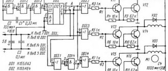
The most acceptable option would be a regulator based on a triac or thyristor. Not only does such a regulator not reduce power when the voltage decreases, it also allows for smoother starting and speed control. In addition, such a scheme can be made with your own hands. Below is a picture of the speed control with power maintenance. The circuit is assembled on the basis of a BTA 41,800 V triac.
All ratings of electrical elements are indicated in the diagram. This is the circuit after assembly, it works quite stably and provides smooth adjustment of the brushed motor. When the output voltage decreases, the power does not decrease, which is a significant plus.
If desired, you can assemble the speed controller of a 220 V brushed motor with your own hands. This circuit is assembled on the basis of a VTA26-600 triac, which must first be installed on a radiator, since this element gets quite hot under load.
The diagram looks like this.
It can successfully cope with the adjustment of power tools such as a drill, grinder, circular saw, and jigsaw. If desired, you can use the circuit as a power regulator for heating elements, heaters, and as a dimmer. The disadvantages include the impossibility of adjusting the power of devices powered by direct current.
https://youtube.com/watch?v=vVeR4jVfTIg
Varieties of models, speed controllers
Speed control devices for single-phase, three-phase and asynchronous motors differ in the fundamental change in rotation speed:
- regulators assembled on thyristors;
- triac speed change systems;
- frequency regulators;
- transformer based regulators.
Thyristor speed controllers are used for single-phase motors and, in addition to changing rotation speeds, allow you to protect equipment from overheating and voltage surges.
Triac devices can control several electric motors at once, operating on both direct and alternating current, but provided that the power parameters do not exceed the limit values. This method of changing the speed is one of the most popular if it is necessary to regulate the speed by changing the voltage readings from the minimum to the nominal value.
A three-phase regulator is more accurate and is equipped with a fuse that controls the current level. And to reduce noise effects at low speeds, a smoothing filter consisting of a capacitor is installed.
A variable speed controller for an asynchronous motor is used to convert the input voltage in the range from 0 to 480 volts, and direct control of the speed is carried out by changing the supplied electrical energy. Most often, such regulators are used in three-phase motors, air conditioning and ventilation systems of sufficiently high power.
Also, for powerful electric motors, a regulator based on a single-phase or three-phase transformer is used. Thanks to this device, it becomes possible to stepwise adjust the speed of the motors. In this case, one transformer can control several devices at once in automatic mode.
Types of devices
Triac device
The triac device is used to control lighting, power of heating elements, and rotation speed.
The controller circuit based on a triac contains a minimum of parts shown in the figure, where C1 is a capacitor, R1 is the first resistor, R2 is the second resistor.
Using a converter, power is regulated by changing the time of an open triac. If it is closed, the capacitor is charged by the load and resistors. One resistor controls the amount of current, and the second regulates the charging rate.
When the capacitor reaches the maximum voltage threshold of 12V or 24V, the switch is activated. The triac goes into the open state. When the mains voltage passes through zero, the triac is locked, and then the capacitor gives a negative charge.
Measurements
It is clear that the number of revolutions needs to be determined somehow. Tachometers are used for this. They show the rotation number at the moment. You can’t simply measure speed with a regular multimeter, except in a car.
As you can see, on electric machines you can change various parameters, adjusting them to the needs of production and household use.
DIY birthday decor
Close…
Pointed-toe cowboy bootsThe principle of operation of a homemade lock is as follows. In one half there is a permanent magnet. and in the other there is a metal plate. One of them is attached to the door. The second, with the metal plate removed, is equipped with a KEM-1 reed switch and attached to the door frame. If the door is in the closed position, the two parts of the lock are pressed, the magnet acts on the reed switch, closing its contacts. If the door opens, the magnet goes away and the reed switch contacts open.
The battery, the computer system unit, even the power supply for a laptop are all best friends. I’m already silent about such good hot water bottles as my husband and I.
Take the filler and stuff the doll. When the stuffing is completely evenly distributed, sew the product up. The handles must be sewn to the body almost near the neck.
From one pallet, sanded, impregnated and varnished, you get a garden table like a coffee table, on the left in Fig. If you have a pair in stock, you can make a wall-mounted work desk-rack out of them in literally half an hour, in the center and on the right. You can also weave chains for it yourself from soft wire, covered with a PVC tube or, better, heat-shrinkable. To fully raise the tabletop, small tools are placed on the shelf of a wall pallet.
Well, if you fill a glass bowl, vase, candy dish, punch vessel or ordinary glasses with water, scattering sea pebbles on the bottom, and let the candle-tablets float freely, you will get magical lighting for a romantic New Year. For a more interesting and unexpected effect, you can experiment with the color of the water. How are studs installed on rubber?
Handmade toys for children are beautiful, cheap and enjoyable. Every child needs original and educational toys, but it is not always possible to purchase them. Today we will show you 5 examples of fun toys that you can make yourself. They can be made from cardboard, paper or wood. In general, be inspired and make your children happy more often.
For the base of such a structure, you can use thick plywood, and for its upper part - polycarbonate. Finding solar panels online today is also not a problem.
Attention! When joining panels, do not use too much force, as you may damage the joint. This is exactly how many knives a housewife should have in her kitchen so that the cooking process is always simple and enjoyable.
This is exactly how many knives a housewife should have in her kitchen so that the cooking process is always simple and enjoyable.
To make a feeder with your own hands we will need:
Timber calculation. The boards, called staves, have biconvex sides to give the cooperage product a convexity. To make them like this, you need to take the lower part of a tree trunk and split it, similar to chopping wood. If you cut it carefully, the natural integrity of the fibers will be disrupted, which is bad for such a product. You shouldn’t start figure sawing right away - the logs need to be dried for 2 months. Moreover, dry it not under the scorching sun, but in a dark, cool room.
How to weave bracelets from laces
The fact that most New Year's costumes for preschool children are easily sewn on the basis of overalls can significantly narrow and facilitate creative search. If you learn how to sew a jumpsuit - the basis for a New Year's costume and come up with (draw from) and make decorative elements for it with your own hands, then you can make amazing and quite interesting models of New Year's outfits for children. The main thing is to think through everything in advance to the smallest detail, arm yourself with knowledge on the topic - so that the result of the work will pleasantly surprise and delight everyone.
Wardrobe design
Images
DIY birthday gift for mom photo instructions
Similar news
.
With the ever-increasing growth of automation in the domestic sector, there is a need for modern systems and devices for controlling electric motors.
Control and frequency conversion in small-power single-phase asynchronous motors, launched using capacitors, allows you to save energy and activates the energy saving mode at a new, progressive level.
Making homemade relays
Making a homemade speed controller for a 12 V electric motor will not be difficult. For this work you will need the following:
- Wirewound resistors.
- Switch for several positions.
- Control unit and relay.
The use of wirewound resistors allows you to change the supply voltage and, accordingly, the engine speed. Such a regulator provides stepwise acceleration of the engine, has a simple design and can be made even by novice radio amateurs. Such simple homemade step regulators can be used with asynchronous and contact motors.
Operating principle of a homemade converter:
- Power from the network is sent to the capacitor.
- The used capacitor is fully charged.
- The load is transferred to the resistor and the bottom cable.
- The thyristor electrode connected to the positive terminal on the capacitor receives the load.
- A voltage charge is transmitted.
- The discovery of the second semiconductor occurs.
- The thyristor passes the load received from the capacitor.
- The capacitor is completely discharged, after which the half-cycle is repeated.
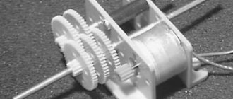
In the past, the most popular were mechanical regulators based on a variator or gear drive. However, they were not very reliable and often failed.
Homemade electronic regulators have proven themselves to be the best. They use the principle of changing step or smooth voltage, are durable, reliable, have compact dimensions and provide the ability to fine-tune the operation of the drive.
The additional use of triacs and similar devices in electronic regulator circuits allows for a smooth change in voltage power; accordingly, the electric motor will correctly gain speed, gradually reaching its maximum power.
DC Power Regulators
Sometimes there is a need to adjust the speed of a brushed DC motor.
If the consumer does not have a lot of power, then it is possible to connect a variable resistor in series, but then the efficiency of such a regulator will drop sharply. There are schemes with which it is possible to regulate the speed quite smoothly without reducing efficiency. Such a regulator is suitable for changing the brightness of various lamps, supply voltage not exceeding 12 V. This circuit also acts as a speed stabilizer; when the mechanical load on the shaft changes, the speed remains unchanged.
This 12V DC motor speed controller circuit is quite suitable for regulating and stabilizing the speed of motors with a current not exceeding 5 A. This circuit includes a bipolar transistor driver and a 7555 timer, which ensures stable operation and smooth regulation speed. The price of the parts is quite low, which is a definite plus. You can also assemble a 12 V electric motor speed controller with your own hands.
Voltage regulation
Speed control in this way is associated with a change in the so-called engine slip - the difference between the rotation speed of the magnetic field created by the stationary engine stator and its moving rotor:
n1—magnetic field rotation speed
n2—rotor rotation speed
In this case, sliding energy is necessarily released - which causes the motor windings to heat up more.
This method has a small control range, approximately 2:1, and can also only be carried out downwards - that is, by reducing the supply voltage.
When regulating speed in this way, it is necessary to install oversized motors.
But despite this, this method is used quite often for low-power motors with a fan load.
In practice, various regulator circuits are used for this.
Autotransformer voltage regulation
An autotransformer is an ordinary transformer, but with one winding and taps from some of the turns. In this case, there is no galvanic isolation from the network, but in this case it is not needed, so savings are achieved due to the absence of a secondary winding.
The diagram shows autotransformer T1, switch SW1, which receives taps with different voltages, and motor M1.
The adjustment is done in steps; usually no more than 5 steps of regulation are used.
Advantages of this scheme:
- undistorted output voltage waveform (pure sine wave)
- good overload capacity of the transformer
Flaws:
- large mass and dimensions of the transformer (depending on the power of the load motor)
- all the disadvantages inherent in voltage regulation
Thyristor engine speed controller
This circuit uses keys - two thyristors connected back-to-back (the voltage is alternating, so each thyristor passes its own half-wave of voltage) or a triac.
The control circuit regulates the moment of opening and closing of the thyristors relative to the phase transition through zero; accordingly, a piece is “cut off” at the beginning or, less often, at the end of the voltage wave.
This changes the rms voltage value.
This circuit is quite widely used to regulate active loads - incandescent lamps and all kinds of heating devices (so-called dimmers).
Another method of regulation is to skip half-cycles of the voltage wave, but at a network frequency of 50 Hz this will be noticeable for the motor - noise and jerking during operation.
To control motors, regulators are modified due to the characteristics of the inductive load:
- install protective LRC circuits to protect the power switch (capacitors, resistors, chokes)
- add a capacitor at the output to adjust the voltage waveform
- limit the minimum voltage regulation power - for guaranteed engine start
- use thyristors with a current several times higher than the electric motor current
Advantages of thyristor regulators:
Flaws:
- can be used for low power engines
- During operation, noise, crackling, and jerking of the engine may occur.
- when using triacs, a constant voltage is applied to the motor
- all the disadvantages of voltage regulation
It is worth noting that in most modern mid- and high-level air conditioners, the fan speed is adjusted in this way.
Transistor voltage regulator
As the manufacturer himself calls it, an electronic autotransformer or PWM regulator.
The voltage is changed using the PWM (pulse width modulation) principle, and transistors are used in the output stage - field-effect or bipolar with insulated gate (IGBT).
The output transistors are switched at a high frequency (about 50 kHz); if you change the width of the pulses and pauses between them, the resulting voltage at the load will also change. The shorter the pulse and the longer the pause between them, the lower the resulting voltage and power input.
For a motor, at a frequency of several tens of kHz, a change in the pulse width is equivalent to a change in voltage.
The output stage is the same as that of a frequency converter, only for one phase there is a diode rectifier and two transistors instead of six, and the control circuit changes the output voltage.
Advantages of an electronic autotransformer:
- Small dimensions and weight of the device
- Low cost
- Clean, undistorted current output waveform
- No hum at low speeds
- 0-10 Volt signal control
Weak sides:
- The distance from the device to the engine is no more than 5 meters (this disadvantage is eliminated when using a remote controller)
- All the disadvantages of voltage regulation
Regulators are standard
As for these components, they are implemented in many ways. The first and simplest circuit is a thyristor circuit. This technology is used in household appliances: washing machines, drills, screwdrivers, vacuum cleaners, etc. They can easily be connected to alternating current networks, including for household purposes.
Standard scheme
The operation of this circuit is quite simple: in all sections of the network currents, the capacitor receives current using a resistor. Charging is carried out to the opening level of the dinistor, which is connected to the regulating electrodes of the sismistor. After this, the latter opens and current passes through it to the CD loads.
The circuit makes it possible to productively regulate the recharging time of the capacitor in the control circuit, as well as determining the average voltage power supplied to the motor.
Let's streamline all the steps of this scheme. Here they are:
- supplying current to the capacitor from a 220 volt power source;
- the voltage for breakdown of the dinistor is also supplied, but through a variable resistor;
- direct breakdown;
- opening of the triac. The component works directly with load indicators;
- the higher the voltage, the more often the triac opens.
This technology provides simple, but at the same time effective regulation of speed intensity. But, at the same time, the use of a standard scheme does not provide feedback, which should also be taken into account when implementing it. Based on this, you also need to know that when the load indicators change, the engine speed will need to be adjusted in parallel.
Triac circuit
This mechanism has many common parameters with a dimmer used to regulate the brightness level of incandescent lamps. There is also no feedback. Implement mono current reverse, but with the use of auxiliary electronics. This is done in order to smoothly maintain power at the specified levels, avoiding overheating and overloads.
Rheostat circuit
It refers to modified schemes, but despite this, its implementation is also simple. With the help, it is possible to stabilize the speed, as well as dissipate the huge amount of generated heat. The adjustment is carried out using a radiator, which must be prepared in advance. It is also necessary to ensure effective heat removal, which leads to energy losses and, as a consequence, efficiency. In order to prevent these shortcomings, it is recommended to use active cooling on an ongoing basis.
Rheostat circuit example
The resulting limiter regulator is distinguished by its efficiency when changing the engine speed. Power transistors, which “take away” a certain portion of the voltage, will also help achieve performance. This is due to the fact that the amount of current from the 220V network reaches the motor in a smaller volume, due to this, the power unit does not encounter heavy loads.
Integral
Stabilization also applies to modified schemes. Here, the control process is based on an integral action timer. Its main task is to control the load levels on the electric motor. Transistors also find their use here. The peculiarity is determined by the microcontroller that is part of the system, which at the same time has high output voltage parameters.
In situations where there is a load of 0.1 ampere, all currents flow directly to the board, bypassing the transistors. To ensure efficient operation of the regulator, it is necessary that there is a voltage of 12V at the gate. Therefore, for smooth operation, the electrical circuit and voltage level in the power source must correspond to this range. The resource of the regulator allows you to install the component in powerful modifications for precise and quick regulation of their operation.
Integrated circuit
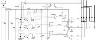
Using Pulse Width Modulation
To control and adjust the speed of rotation of an asynchronous type electric motor, you can use a pulse regulator-voltage stabilizer (inverter). It will act as a power source. It is based on the use of a TL494 pulse PWM regulator. The supply voltage of the electric motor, coming out after the PWM controller, will change in accordance with the change in rotation speed. Using this method, a greater economic effect is achieved, the device is quite simple and at the same time increases the efficiency of regulation.
The figure above shows a diagram of using a PWM controller for a three-phase asynchronous motor connected through a capacitor to a single-phase network.
This method, despite its effectiveness, has two significant drawbacks:
- impossibility of reverse motor control without the use of additional switching devices;
- frequency converters used in the regulator are high cost and are produced by a limited number of manufacturers.
Purpose and functions of regulators
Not so long ago, devices for adjusting the rotation speed of an asynchronous electric motor consisted of simple manual switches and a magnetic relay, thanks to which it was only possible to start the motor at maximum speed or completely turn it off.
Any engine speed controller, including a frequency controller, is designed to change the engine rotation speed. In this case, the main function of the speed controller is to change the performance of the exhaust system or other equipment. But besides this, such devices also have additional capabilities that should not be forgotten:
- reduction of equipment wear during operation;
- saving consumed electrical energy;
- reduction of noise at maximum speed.
Most devices that regulate the rotation speed of an electric motor can be used as a separate element of the system, or as an addition to an electronic control unit, a household appliance driven by a motor.
Operating principle of a single-phase asynchronous machine
When an asynchronous machine is supplied with single-phase power, instead of a rotating magnetic field, a pulsating one appears in it, which can be decomposed into two magnetic fields, which will rotate in different directions with the same frequency and amplitude. When the electric motor rotor is stopped, these fields will create moments of the same magnitude, but of different signs. As a result, the resulting starting torque will be zero, which will not allow the engine to start. In its properties, a single-phase electric motor is similar to a three-phase one, which operates with a strong distortion of voltage symmetry:
Figure a) shows a diagram of an asynchronous single-phase machine, and b) a vector diagram
Main types of single-phase electric drives
As mentioned, a single-phase motor cannot develop starting torque, which makes it impossible to start it independently. To do this, they came up with several ways to compensate for a magnetic field that is opposite in sign to the main one.
Motors with starting winding
In this starting method, in addition to the main winding P, which has a phase zone of 120 0, a starting winding P, which has a phase zone of 60 0, is also wound on the stator. Also, the starting winding shifts relative to the working winding by 90 0 electrical. In order to create a phase shift between the winding currents Ip and Ip, an element leading to a phase shift ψ (phase-shifting resistance Zp) is connected in series to the starting winding:
Where: a) connection diagram of the machine, b) vector diagrams when using different resistances.
The best conditions for starting are to include a capacitor in the starting winding. But since the capacitor capacity is quite large, its cost and dimensions also increase accordingly. It is often used to obtain increased starting torque. Inductive starting has the worst performance and is not currently used. Quite often, starting with the help of active resistance can be used, while the starting winding is made with increased active resistance. After the electric motor starts, the starting winding is turned off. The connection diagrams and their starting characteristics are shown below:
Where: a, b) motors with a starting winding, c, d) capacitor motors
Capacitor motor
This type of electric motor has two working windings, one of which is connected to the working capacitance Cp. These windings are shifted relative to each other by 90 0 electrical and have phase zones also 90 0. In this case, the powers of both windings are equal, but their currents and voltages are different, and the number of turns is also different. Sometimes the size of the working capacitor is not enough to generate the required starting torque, so a starting one can be hung in parallel with it, as shown in the figure above. The diagram is shown below:
Where: a) circuit of a capacitor electric motor, b) its vector diagram
In this type of single-phase machines, the power factor cosφ is even higher than that of three-phase machines. This is due to the presence of a capacitor. The efficiency of such an electric motor is higher than that of a single-phase electric motor with a starting winding.
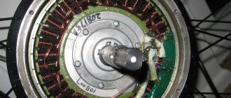
Types of engines and operating principles
Motors are divided into three types: commutator, asynchronous and brushless. Most power tools use the first type. This electric motor has a fairly compact size. Its power is significantly higher than that of asynchronous, and the price is quite low. As for asynchronous ones, this type is mainly used in the metalworking industry, and they are also widespread in coal mines. Quite rarely they can be found in everyday life.
The brushless electric motor is used where high speeds, precise positioning and small dimensions are needed. For example, in various medical equipment, aircraft modeling. The principle of operation is quite simple. If a rectangular frame, which has an axis of rotation, is placed between the pluses of a permanent magnet, then it will begin to rotate. The direction depends on the direction of the current in the frame. This type contains an armature and a stator. The armature rotates, but the stator stands still. As a rule, there is not one frame at anchor, but 4.5 or more.
An asynchronous motor works on a different principle. Thanks to the effect of an alternating magnetic field in the stator coils, it is driven into rotation. If you delve deeper into the course of physics, you can remember that a kind of magnetic field is created around the conductor through which the current passes, causing the rotor to rotate.
The principle of operation of the brushless type is based on turning on the windings so that the magnetic fields of the stator and rotor are orthogonal to each other, and the torque is regulated by a special driver.
The figure clearly shows that in order to move the rotor it is necessary to perform the necessary commutation, but it is not possible to regulate the speed. However, the brushless motor can rev up very quickly.
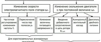
Changing the speed of an IM with a squirrel-cage rotor
There are several ways:
- Rotation control by changing the electromagnetic field of the stator: frequency regulation and changing the number of pole pairs.
- Changing the slip of the electric motor by decreasing or increasing the voltage (can be used for IMs with a wound rotor).
Frequency regulation
In this case, the adjustment is made using a frequency conversion device connected to the engine. For this purpose, powerful thyristor converters are used. The process of frequency regulation can be considered using the example of the EMF formula of a transformer:
This expression means that in order to maintain a constant magnetic flux, which means maintaining the overload capacity of the electric motor, the supply voltage level should be adjusted simultaneously with frequency conversion. If the expression calculated by the formula is saved:
then this means that the critical moment has not been changed. And the mechanical characteristics correspond to the figure below; if you do not understand what these characteristics mean, then in this case the adjustment occurs without loss of power and torque.
The advantages of this method are:
- smooth regulation;
- changing the rotor speed up and down;
- rigid mechanical characteristics;
- efficiency.
There is only one drawback - the need for a frequency converter, i.e. increase in the cost of the mechanism. By the way, on the modern market there are models with single-phase and three-phase input, the cost of which with a power of 2-3 kW is in the range of 100-150 dollars, which is not too expensive for full adjustment of the drive of machine tools in a private workshop.
Switching the number of pole pairs
This method is used for multi-speed motors with complex windings that allow you to change the number of pairs of its poles. The most widely used are two-speed, three-speed and four-speed IMs. The adjustment principle is easiest to consider on the basis of a two-speed IM. In such a machine, the winding of each phase consists of two half-windings. The rotation speed changes when connecting them in series or parallel.
In a four-speed electric motor, the winding is made in the form of two parts independent from each other. When the number of pole pairs of the first winding changes, the speed of the electric motor changes from 3000 to 1500 rpm. Using the second winding, rotation is adjusted at 1000 and 500 rpm.
When the number of pole pairs changes, the critical moment also changes. To keep it unchanged, it is necessary to simultaneously regulate the supply voltage while changing the number of pole pairs, for example, by switching the star-delta circuit and their variations.
Advantages of this method:
- rigid mechanical characteristics of the engine;
- high efficiency.
- step adjustment;
- large weight and overall dimensions;
- high cost of the electric motor.
Engine device
To make a speed controller with your own hands, you will first need to understand the details. The high demand for self-assembly lies in its versatility. By making a simple speed controller with your own hands, you can use it in various situations. So, first, let's understand a little about the structure of a simple commutator motor.
It consists of the following components:
- Collector.
- Brushes.
- Rotor.
- Stator.
Operating principle of a commutator motor:
- The source of electricity is a standard 220 V socket. Power goes to the main winding.
- After electricity is supplied from a source to the stator winding, a magnetic field is created in it.
- The magnetic field drives the rotor.
- Through graphite brushes, the voltage is transmitted to the commutator, whose task is to constantly switch the direction of the current so that the rotor ultimately rotates in one direction.
Design Features
The microcircuit is equipped with everything necessary for high-quality engine control in various speed modes, from braking to acceleration and rotation at maximum speed. Therefore, its use greatly simplifies the design, while simultaneously making the entire drive universal, since you can select any speed with a constant torque on the shaft and use it not only as a drive for a conveyor belt or drilling machine, but also for moving a table.
The characteristics of the microcircuit can be found on the official website. We will indicate the main features that will be required to construct the converter. These include: an integrated frequency-to-voltage conversion circuit, an acceleration generator, a soft starter, a Tacho signal processing unit, a current limiting module, etc. As you can see, the circuit is equipped with a number of protections that will ensure stable operation of the regulator in different modes.
The figure below shows a typical circuit diagram for connecting a microcircuit.
The scheme is simple, so it is quite reproducible with your own hands. There are some features that include limit values and speed control method:
- The maximum current in the motor windings should not exceed 10 A (subject to the configuration shown in the diagram). If you use a triac with a large forward current, the power can be higher. Please note that you will need to change the resistance in the feedback circuit downward, as well as the inductance of the shunt.
- The maximum rotation speed is 3200 rpm. This characteristic depends on the type of engine. The circuit can control motors up to 16 thousand rpm.
- Acceleration time to maximum speed reaches 1 second.
- Normal acceleration is achieved in 10 seconds from 800 to 1300 rpm.
- The engine uses an 8-pole tachogenerator with a maximum output voltage of 30 V at 6000 rpm. That is, it should produce 8 mV per 1 rpm. At 15,000 rpm it should show 12 V.
- To control the motor, a 15A triac with a maximum voltage of 600 V is used.
If you need to organize a motor reverse, then for this you will have to supplement the circuit with a starter that will switch the direction of the excitation winding. You will also need a zero speed control circuit to give permission for reverse. Not shown in the picture.
DIY making
If there is no opportunity or desire to purchase a factory-type regulator, then you can assemble it yourself. Although regulators of the "tda1085" type have proven themselves very well. To do this, you need to familiarize yourself with the theory in detail and start practicing. Triac circuits are very popular, in particular the speed controller of a 220V asynchronous motor (diagram 5). It's not difficult to make. It is assembled using a VT138 triac, which is well suited for these purposes.
Scheme 5 - Simple speed controller on a triac.
This regulator can also be used to adjust the speed of a 12-volt DC motor, as it is quite simple and universal. The speed is regulated by changing the parameters P1, which determines the phase of the incoming signal, which opens the transition of the triac.
The operating principle is simple. When the engine starts, it slows down, the inductance changes downward and contributes to an increase in U in the “R2—>P1—>C2” circuit. When C2 is discharged, the triac opens for some time.
There is another scheme. It works a little differently: by providing a reverse type of energy flow, which is optimally beneficial. The circuit includes a fairly powerful thyristor.
Scheme 6 - Design of a thyristor regulator.
The circuit consists of a control signal generator, an amplifier, a thyristor and a circuit section that functions as a rotor rotation stabilizer.
The most universal circuit is a regulator based on a triac and dinistor (scheme 7). It is able to smoothly reduce the shaft rotation speed, reverse the motor (change the direction of rotation) and reduce the starting current.
The principle of operation of the circuit:
- C1 is charged until U breakdown of dinistor D1 through R2.
- When D1 breaks, it opens the junction of triac D2, which is responsible for controlling the load.
The load voltage is directly proportional to the frequency component when D2 opens, which depends on R2. The circuit is used in vacuum cleaners. It contains universal electronic control, as well as the ability to easily connect 380 V power. All parts should be placed on a printed circuit board made using laser-iron technology (LUT). You can find out more about this board manufacturing technology on the Internet.
Thus, when choosing an electric motor speed controller, you can buy a factory one or make it yourself. Making a homemade regulator is quite simple, since if you understand the principle of operation of the device, you can easily assemble it. In addition, you should follow safety rules when installing parts and when working with electricity.
Smooth engine operation, without jerks or power surges, is the key to its durability. To control these indicators, an electric motor speed controller is used for 220V, 12V and 24V; all of these frequencies can be made with your own hands or you can buy a ready-made unit.