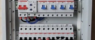
In recent decades, the range of protective electrical devices has been supplemented with residual current devices (RCDs), differential circuit breakers (DIFs), and surge protection devices (SPDs). The listed protection devices make it possible to increase the safety of operation of electrical networks. This material is dedicated to RCD. More precisely, one of the varieties of residual current devices - an electromechanical RCD.
On a note! RCDs are often called residual current devices (RCDs). This name is associated with the principle of operation of protective devices. The design and principle of operation of the UDT will be discussed below.
Purpose of RCD
Most current protection devices (fuses, circuit breakers, etc.) protect electrical wiring and electrical receivers connected to it from overload and short circuit currents. Residual current devices perform other functions. Depending on the triggering current, they protect people from electric shock or prevent fire.
Every electrician knows that industrial frequency alternating current flowing through the human body becomes hazardous to health if its value exceeds 0.01 ampere. Currents above 0.1 A are deadly. Therefore, the threshold operating current (setting) of the RCD protecting a person from electric shock is usually selected from the ratings of 10 mA or 30 mA. The first setting is used for damp rooms, children's rooms, and so on. The 30 mA setting applies to normal conditions.
To prevent fires, devices are installed that are configured for differential currents exceeding 300 mA.
Correct connection diagram for RCD and circuit breaker installation errors
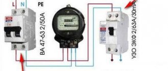
Stable operation of the RCD in electrical applications is ensured by a suitable circuit. The main groups of product designations must comply with GOST. In the circuit, before installing the RCD, it is necessary to install the AB.
The connection is made according to schemes depending on the type of electrical line:
- Connection without grounding - for single-phase wiring, for three-phase wiring.
- With existing grounding - for the TN-CS, TN-S system, for a single-phase or three-phase network.
The circuit breaker and the RCD must work together in the power supply circuit. The machine is located in front of the protection device. Install the RCD in the electrical installation panel.
Installation errors lead to improper operation of the device.
The most common of them:
- Galvanic connection of the neutral protective and working neutral conductors in the area of the product. In this case, a difference appears, since part of the current will flow past the device along the grounding conductor, which will lead to a false operation of the device.
- The neutral working wire is used as the neutral protective conductor. Using also an external conductor for these purposes. These cases lead to incorrect operation of the RCD.
For general consumer protection, an introductory RCD is installed directly after the AV.
Operating principle of an electromechanical RCD
Residual current devices respond to leakage currents that occur when the insulation of electrical wiring is broken or when a person touches live parts that are energized. The main feature of leakage currents is that they upset the balance (equality) of currents flowing through the phase wires and the neutral wire.
A differential transformer is used to detect leakage. Structurally, it consists of:
- a ferrite ring serving as a magnetic circuit (core);
- primary windings, which are phase conductors and a neutral wire passed through the core;
- secondary (measuring) winding.
In the absence of leakage currents, the total magnetic flux created in the transformer core by the primary windings is zero. In this case, there is no EMF in the secondary winding. If a leak occurs, the balance of currents is disrupted and an EMF begins to be induced in the secondary winding. A potential difference occurs at the terminals of the measuring winding. The higher the leakage current, the higher the potential difference.
On a note! Electrical protection based on comparison of currents is called differential current protection .
The voltage removed from the secondary winding of the differential measuring transformer is supplied to the threshold organ (comparison device). The threshold organ generates a shutdown signal when the leakage current reaches the set value.
A polarized relay is used as a threshold element in electromechanical disconnecting devices. In an electronic RCD, the comparison device is a DC amplifier made on an operational amplifier chip.
According to the diagram on the RCD body
On the body of all modern RCDs its electrical circuit is depicted. If it is not on the front of the case, look at the top.
The electronic RCD circuit is somewhat different from the electromechanical circuit. If you know these differences, you can easily recognize the type of RCD before purchasing.
Electro-mechanical RCD diagram:
- differential transformer drawn
- a relay is drawn that is connected to a transformer
- disconnecting mechanism drawn
- the TEST button is still displayed
An example of such a scheme:
Electronic RCD diagram:
The elements that are depicted on the electronic RCD diagram are almost no different from those indicated on the electromechanical one. What's the difference? And it consists of an additional electronic board.
Two conductors are suitable for this element - phase and neutral, that is, 220V. This is the external power required for the operation of the electronic RCD.
Electromechanical UDT device
Electromechanical RCDs consist of the following main parts:
- housings;
- contact system consisting of terminals to which power wires are connected, moving and fixed contacts used for switching;
- instrument transformer and rectifier;
- polarized relay;
- mechanical shutdown systems (release);
- electric arc extinguishing systems;
- test button and resistor.
Purpose of some elements
Polarized relay
The executive element in electromechanical differential current devices is a polarized relay. A polarized relay belongs to the class of bistable DC relays. It can be either in the off or on state in the absence of voltage on its winding. In the RCD, the winding of the polarized relay receives rectified voltage from the measuring transformer. When the threshold value is reached, the relay switches, which is mechanically connected to the release. As a result, the UDT is turned off.
TEST button
Unlike circuit breakers and other protective devices, RCDs have the ability to check the functionality of the device. The test is performed by pressing the “Test” button. This button, together with a specially selected resistor, forms a chain that simulates the occurrence of leakage current. The ends of the chain are connected to the neutral and phase wires. The string conductors do not pass through the ring core of the differential transformer. Therefore, during the test, the balance of magnetic fluxes in the measuring system is disrupted. The resistor value is chosen so that the artificial leakage current is equal to the rated operating current of the differential protection.
Criteria for correct selection
Rated current
The first thing you need to pay attention to is what current the device is designed for. To choose the right RCD for current, you must first decide for what purpose the product will be installed. If you want to protect a separate network element, for example, a washing machine, an electric floor heating system or a water heater (boiler), the value can be no higher than 16 A
For all electrical wiring in the apartment, you need to install the unit at least 32 A. To select the correct value, you first need to calculate the load from all connected electrical appliances and, based on the resulting amount, select the most suitable RCD model. Manufacturers usually indicate the rated current load on the case of modern equipment, so calculations should not be difficult.
Differential current
We have considered all the existing values, which range from 10 to 500 mA, now we will figure out which RCD is better to choose based on amperage in certain situations. Protection of a person from electric shock is provided by settings from 6 to 100 mA. At the same time, leaks above 30 mA will be felt by the human body. That is why it is better to choose a 10 mA model for children’s rooms and bathrooms, and 30 mA to protect sockets and lamps.
It should also be noted that each electrical appliance has a natural leakage current, which is indicated in the attached technical data sheet. When choosing an RCD based on leakage current, be sure to take into account the following rule: the sum of natural leakages should not exceed the rated value of the protective device by more than 30% (1/3). Otherwise, false positives will occur, which will cause a lot of trouble.
Product type
So, in simple words we explain the purpose of each type of RCD:
- AC - mainly used to protect electrical appliances at home when using both single-phase and three-phase networks. Such a product cannot protect household appliances with pulsating current, for example, a washing machine.
- A - is used specifically for separate protection of washing machines in apartments and private houses.
- B - mainly used in production, so there is no point in choosing this type for home.
- S - as we have already said, shutdown does not occur immediately when a leak is detected, but after a certain time setting. As a rule, it is used to prevent fire and is connected at the input panel, servicing all electrical wiring (therefore, the setting for the leakage current is selected at least 100 mA).
- G – mainly connected to a separate electrical device for control and timely fire protection. Unlike the “S” type, it has a shorter exposure time.
Design
There is nothing special to talk about here; electronic ones have a more complex operating principle and function only if there is a power source (external or mains power). Electromechanical ones are more reliable and durable, so it is better to choose an electromechanical RCD for an apartment or house, and the cost will be much lower.
Manufacturer
Well, the last, no less important criterion for choosing an RCD is based on the manufacturer. Today, the best companies in the production of these products are the following companies:
- Legrand;
- ABB;
- AEG;
- Schneider electric;
- Siemens;
- DEKraft.
Among budget models, the highest quality is from the companies Austro-UZO and DEK.
We recommend giving preference to more expensive products, but if the budget does not allow, domestic manufacturers will also cope well with protection. In any case, before purchasing, we advise you to visit electrical forums and read customer reviews about the chosen model! This way you will probably find out all the advantages and disadvantages of the product and determine exactly which RCD is better to choose.
The difference between an electronic RCD and an electromechanical UDT
Electronic and electromechanical protection devices differ only in the type of threshold device. As noted above, electronic protection devices use an electronic amplifier as a threshold device, which generates a shutdown signal. This signal is sent to a conventional relay, which acts on a mechanical release. Electronic components, unlike electromechanical relays, are cheaper and have less technological variation. Therefore, an electronic RCD, as a rule, costs less than an electromechanical protection device.
People who have not previously encountered residual current devices often ask the question: how to distinguish an electromechanical RCD from an electronic one? Devices can be identified by markings on the front of the device. For all RCDs on the body you can see a symbolic image of a differential transformer. It is depicted as an ellipse enclosing power conductors. A symbolic communication line is drawn from the transformer going to the comparison device. The comparison device is depicted as a rectangle or triangle. If a triangle is drawn, then this is an electronic RCD. If the rectangle is an electromechanical device.
Important! If one or all of the images of the phase conductors connected to the moving contacts have bends in the form of an arc or a rectangular protrusion, then you are dealing with a circuit breaker. These bends represent the electromagnetic and thermal release respectively. If a measuring transformer and a comparison device are added to the “bends”, then this is a difavtomat.
On a note! All RCDs always have an even number of poles. Devices used in a single-phase network have two poles - phase and zero. Three-phase UDTs respectively have 4 poles. Zero terminals are always marked with the Latin letter “N”.
The eternal dispute about RCD
On electricians forums, debates continue on the topic: which protection device is better to use, electronic or electromechanical RCD?
In principle, there are no functional differences between devices with different threshold devices. Both types of differential current devices successfully perform their functions. But meticulous researchers have noticed one feature that the electronic RCD has. An op amp requires power to operate. It is taken from the input terminals of the protection device. Therefore, in the event of a break in the zero or phase supplying the electronic circuit, the device loses its functionality. An electromechanical RCD is free of this drawback, since the actuator is powered from the secondary winding of the transformer. Therefore, if the neutral wire breaks, the “electromechanics” will still work in the event of a phase leak.
Division of devices by number of poles
There are two types of RCDs according to the number of poles: two-pole, which are installed in a network with a power of 220 volts, and four-pole for a network of 380 volts.
The most widespread in housing construction are two-pole circuit breakers, which are installed in apartment panels. Four-pole ones are designed to protect three-phase wiring and are most often used in industrial electric motors.
An ouzo socket will help increase the reliability of your apartment, which will ensure your safety when using any household appliance. And the ouzo-fork will protect you when operating devices in any adverse environmental conditions.
How to choose the right RCD
We discussed the issue of using electronic and electromechanical devices above. They also talked about choosing a setting for different types of premises. There is one more parameter that should be taken into account when choosing a UDT. This parameter is the rated operating current. That is, the current that the RCD can withstand for an unlimited amount of time. When choosing a working “nominal value” you can follow a simple rule. The operating current must be no lower than the operating current of the machine, which protects the supply line from short circuit and overload.
What to consider when choosing an RCD
In order to choose an effective and safe device, you need to know some factors:
- Understanding the purpose and principle of operation of the device you have chosen;
- Know exactly its parameters and characteristics;
- Study the regulatory documents supplied with the device.
An important role when choosing a machine is the age of your wiring, the condition and quality of the connections. Whether your apartment is new or old, whether there is a transformer substation nearby, the temperature conditions of the room where the electrical panel is installed - these are factors that influence the choice of a device that will protect you in any adverse situations.
A typical home electrical circuit diagram should look like this:
- Input electrical panel;
- Electrical panel on the lower floor;
- Electrical panel on the second floor;
- Each floor of the house has an electrical panel equipped with a group of automatic circuit breakers, individually for each apartment.
There are different types of RCDs, each of which performs specific tasks. Let's look at the indicators by which RCDs are classified.
Gradation:
- type of current leakage;
- response time;
- shutdown principle;
- number of poles.
Before making a purchase, you should determine exactly why you need the machine and what load it must withstand.
How to properly connect residual current devices
When connecting leakage current protection devices, several basic rules must be observed.
First and most important. RCDs and automatic devices must be operated in networks with a solidly grounded neutral with a separate grounding wire (three-wire or five-wire system). In this case, the housings of all electrical receivers protected by devices from leakage currents must be reliably grounded. Grounding can be carried out through the socket contacts or with a separate bolt-on wire.
Dangerous! Never use the neutral wire as grounding. Only a separate land!
Second. It is necessary to ensure that the wires are connected correctly. Zero should be connected to the terminals marked with the letter “N”, and phases to the phase terminals. This rule, which at first glance is not obvious, is associated with connecting the test button and the electronic protection circuit.
Third. Conductors of the same name protected by different RCDs cannot be connected to each other. This mistake is often made by inexperienced electricians when they use a common zero for several socket blocks. Such a connection, when connecting a load, immediately triggers the protection.
What needs to be protected?
If we are talking about RCDs , then you need to understand that we are protecting people first of all. We protect against direct contact with parts of equipment and electrical wiring that contain dangerous potential. The potential there may be normal, to ensure normal operation (as at the phase terminal of a socket), or it may appear as a result of an accident (for example, 220 V may appear on the body of a washing machine due to poor insulation of the heating element).
PUE recommends installing RCDs on all outlet lines (PUE 7.1.71) , but usually they are not installed in dry rooms. But I think it’s better not to save money, but to put them on each group (line).
RCD is an additional protection against direct contact. The main protection against direct contact is primarily insulation and a circuit breaker. Everything is clear with insulation, but the machine should work if a phase hits the ground.
“It should” - but it won’t always succeed, since the short circuit current is sometimes insufficient to work on electromagnetic protection, but on thermal protection it can work in a second, or in an hour, or never. I have written about this more than once. In this case, it is necessary to install an RCD (PUE 7.1.72) .
The protection works on the principle of comparing the difference (differential) of currents in phase and zero. Current can “leak” for various reasons - poor insulation, short circuit, touch - but in all cases, if the leakage current is sufficient, the RCD will de-energize its line.
Here we can recall Kirchhoff’s first law for a closed loop, which can be expressed as follows: the current “flowing” from the power source is equal to the “flowing” current. If these currents are not equal, then there is a leak somewhere and the RCD should react.
By the way, leakage can occur not only from phase to ground. It can be from the neutral wire or to another phase. In any case, if the current finds a “loophole” and begins to leak out of the closed circuit, and when a certain value of the leakage current is reached, the RCD will turn off.
How to quickly check an RCD without connecting to the network
Each leakage current protection device has a test button. With its help, it is easy to carry out periodic checks of the UDT during operation. To test a large batch of disconnecting devices that are not connected to the network, you can use a regular 1.5 V AA battery.
If it is connected to the same poles (for example, to terminals 1-2), a working device will work instantly, since the current pulse during connection will not be balanced by the reverse current. RCDs with a rated differential current of 10 or 30 mA are triggered even by a dead battery.
Checking the RCD using a battery
Necessary equipment for testing:
- ⚡
battery (pen or crown) - ⚡
two wires 10-15cm long
The verification process is as follows. Connect one of the wires to the upper contact of the RCD, the other wire to the lower contact. The main thing is that the contact is single-pole, i.e. either the phase of the same name (if it is a 3-phase RCD), or zero. And close the wires to the plus and minus of the battery.
If the RCD does not turn off, reverse the connection poles of the wires on the battery. If it didn’t work this time, it means the RCD is electronic.
Triggering of an RCD means that it is of the electromechanical type.
Marking, main characteristics of RCD
In order not to confuse RCDs with other similar devices (circuit breakers and automatic circuit breakers), let us dwell on their markings. In addition, knowledge of the markings will help you choose and connect the RCD correctly. The RCD marking contains a connection diagram and the main selection parameters: rated current (A), differential current (mA), operating voltage (V), conditional limit short-circuit current (A). The table provides a more detailed description of the main characteristics of the RCD and other designations that manufacturers may provide in the technical documentation.
| Name | Decoding |
| Un, V | Rated voltage (electronic RCDs are very sensitive to voltage surges) |
| In, A | Rated load current (maximum current that the RCD can pass for a long time without harm to the device) |
| fn, Hz | Rated network frequency |
| I∆n, mA | Rated residual current or sensitivity, setting by leakage current (leakage current at which the RCD is triggered) |
| I∆no, mA | Rated non-tripping differential current (at which the RCD should not trip). Formula IΔn0 = 0.5 IΔn. |
| Im, A | Rated switching capacity. Formula Im = 10 In |
| I∆m, A | Rated making and breaking capacity for differential current |
| Inc, A | Rated conditional short-circuit current (resistance to short-circuit currents) |
| I∆c, A | Rated differential short-circuit current |
| Tn, ms | Tripping time at rated differential current |
| N | The neutral conductor is designated by the letter N (neutral). |
| Indicator | Contact position indicator - shows whether the RCD was turned off manually or whether it was triggered by a leak. |
Main features of the ABB F202 series machine
- Residual current device
- Rated currents from 16 to 63 A
- Leakage currents from 10 mA to 300 mA
- Breaking capacity 10
- The use of an innovative solution - a cylindrical bidirectional terminal, allows you to simultaneously connect two conductors, both from below and from above
- Possibility of simultaneous connection of wires of different sections
- Possibility of connecting both single-core and stranded conductors
- A special mount allows you to easily remove the device from the DIN rail without dismantling the distribution bus - just push up
- Power connection from above or below, distribution busbars from above or from below, the busbar is connected to the rear terminal, the cable to the front, the connection point is clearly visible
- Connecting wires with a cross-section of up to 50 mm2 vertically or laterally using an additional adapter
- A wide range of accessories can be used (disconnectors, contacts, etc.)
- Marking holder allows the protected circuit to be clearly identified
- There is a “test” button to check the functionality of the device
- A unique serial number is assigned to verify the authenticity of the device
- The contact position indicator allows you to determine their current state (red – contacts are closed, green – open)
Who should buy ABB F202
Purpose: protection against alternating sinusoidal leakage current to ground, protection against indirect contact and additional protection against direct contact, disconnecting the power supply to circuits with resistive and inductive loads.
Application: residential premises, commercial and industrial facilities.
Differences between ABB RCD series F200 and FH200
The F200 series RCD (or VDT, residual current circuit breaker) is a professional series of modular equipment. Its main area of application is industrial and commercial facilities, but it is also well suited for installation in household panels. ABB supplies these devices in two- and four-pole versions, both for alternating current (type AC) and alternating and pulsating direct current (type A). They have bidirectional terminals that allow you to simultaneously connect two conductors, both from below and from above. It is possible to connect additional control and alarm devices.
The FH200 series is a budget version of the F200, aimed at installation in household and office power supply systems. It is part of the Compact Home line and provides the consumer with all the advantages of this model range, such as compact dimensions and lower cost compared to the professional series. The price reduction was achieved by eliminating functions that do not affect reliability and are not in demand in the private sector. Also, devices in this series do not have the ability to connect auxiliary accessories. FH200 RCDs are available in two- and four-pole versions for alternating current networks (AC type). Externally, they differ from the devices of the older series in the color of the handle - it is black.
| Specifications | F200 | FH200 |
| Rated current | 16–125 A | 25–63 A |
| Voltage | 230/400 V | |
| Nominal sensitivity | 10, 30, 100, 300 and 500 mA | 30, 100, 300 mA |
| Rated short circuit current | 10 kA | 6 kA |
| Connected cable cross-section | up to 35 mm 2 | up to 25 mm 2 |
