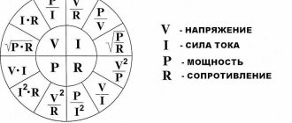
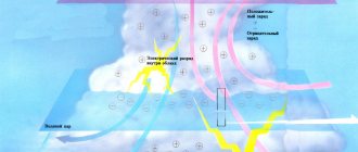
During operation, electrical circuits are constantly closed and opened. It has long been noted that at the moment of opening an electric arc is formed between the contacts. For its appearance, a voltage of more than 10 volts and a current of more than 0.1 ampere are sufficient. At higher current and voltage values, the internal temperature of the arc often reaches 3-15 thousand degrees. This becomes the main cause of melted contacts and live parts.
If the voltage is 110 kilovolts or higher, in this case the length of the arc can reach a length of more than one meter. Such an arc poses a serious danger to persons working with powerful power plants, therefore its maximum limitation and rapid extinguishing are required in any circuits, regardless of the voltage.
Further Study
In the late nineteenth century, the voltaic arc was widely used for public lighting. The tendency of electrical arcs to flicker and hiss was a serious problem. In 1895, Hertha Marx Ayrton wrote a series of articles on electricity, explaining that the voltaic arc was the result of oxygen coming into contact with the carbon rods used to create the arc.
In 1899, she was the first woman ever to read her own paper before the Institution of Electrical Engineers (IEE). Her report was entitled "The Mechanism of the Electric Arc." Shortly afterwards, Ayrton was elected as the first female member of the Institution of Electrical Engineers. The next woman was admitted to the institute in 1958. Ayrton applied to read a paper before the Royal Society, but she was not allowed to do so because of her gender, and The Mechanism of the Electric Arc was read in her place by John Perry in 1901.
Destructive potential
An electric arc has a nonlinear relationship between current and voltage. Once the arc has been created (either by progression from the glow discharge or by momentarily touching the electrodes and then separating them), the increase in current results in a lower voltage between the arc terminals. This negative resistance effect requires that some positive form of impedance (like electrical ballast) be placed in the circuit to maintain a stable arc. This property is why uncontrolled electrical arcs in a device become so destructive, because once the arc occurs, it will draw more and more current from the DC voltage source until the device is destroyed.
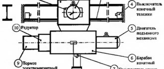
Arc. Conditions for the occurrence and burning of an arc. Arc extinguishing methods.
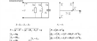
As shown in Fig.
1, the voltage on the arc is the sum of the cathode Uk and anode Ua voltage drops and arc barrel voltage Usd: Ud=Uk+Ua+Usd=Ue+ Usd. If a long arc, which occurs when the contacts are opened, is pulled into an arc-extinguishing grid of metal plates, then it will be divided into N short arcs. Each short arc will have its own cathode and anode voltage drop Ue. The arc goes out if:
Un Ue,
where U is the network voltage; Ue is the sum of the cathode and anode voltage drops (20-25 V in a DC arc).
An AC arc can also be divided into N short arcs. At the moment the current passes through zero, the near-cathode space instantly acquires an electrical strength of 150-250 V.
The arc goes out if
Un.
Arc extinction in narrow slots.
If an arc burns in a narrow gap formed by an arc-resistant material, then due to contact with cold surfaces, intensive cooling and diffusion of charged particles into the environment occurs. This leads to rapid deionization and arc extinction.
Rice. 4. Arc extinguishing methods:
a – division of a long arc into short ones; b – drawing the arc into a narrow slot in the arc-extinguishing chamber; c – rotation of the arc in a magnetic field; d – arc extinguishing in oil: 1 – fixed contact; 2 – arc trunk; 3 – hydrogen shell; 4 – gas zone; 5 – oil vapor zone; 6 – moving contact
Movement of an arc in a magnetic field.
An electric arc can be considered as a conductor carrying current. If the arc is in a magnetic field, then it is acted upon by a force determined by the left-hand rule. If you create a magnetic field directed perpendicular to the axis of the arc, then it will receive translational motion and will be pulled inside the slot of the arc-extinguishing chamber (Fig. 4, b).
In a radial magnetic field, the arc will receive rotational motion (Fig. 4, c). The magnetic field can be created by permanent magnets, special coils, or the circuit of current-carrying parts itself. Rapid rotation and movement of the arc contributes to its cooling and deionization.
The last two methods of extinguishing the arc (in narrow slots and in a magnetic field) are also used in disconnecting devices with voltages above 1 kV.
4. The main methods of extinguishing the arc in devices above 1 kV.
In switching devices over 1 kV, methods 2 and 3 described in paragraphs are used. 1.3. and the following arc extinguishing methods are also widely used:
1. Arc extinction in oil.
If the contacts of the disconnecting device are placed in oil, then the arc that occurs during opening leads to intense gas formation and evaporation of the oil (Fig. 4, d). A gas bubble is formed around the arc, consisting mainly of hydrogen (70-80%); rapid decomposition of the oil leads to an increase in pressure in the bubble, which contributes to its better cooling and deionization. Hydrogen has high arc-quenching properties. Contacting directly with the arc shaft, it contributes to its deionization. Inside the gas bubble there is a continuous movement of gas and oil vapor. Arc quenching in oil is widely used in circuit breakers.
2. Gas-air blast .
Arc cooling is improved if a directed movement of gases is created - blasting. Blowing along or across the arc (Fig. 5) promotes the penetration of gas particles into its barrel, intense diffusion and cooling of the arc. Gas is created during the decomposition of oil by an arc (oil switches) or solid gas-generating materials (autogas blast). It is more effective to blow with cold, non-ionized air coming from special compressed air cylinders (air switches).
3. Multiple current circuit break.
Switching off large currents at high voltages is difficult. This is explained by the fact that at high values of the supplied energy and recovery voltage, deionization of the arc gap becomes more difficult. Therefore, in high-voltage circuit breakers, multiple arc breaks are used in each phase (Fig. 6). Such switches have several extinguishing devices designed for part of the rated value.
yarn The number of breaks per phase depends on the type of switch and its voltage. In 500-750 kV circuit breakers there can be 12 breaks or more. To facilitate arc extinction, the recovery voltage must be evenly distributed between the breaks. In Fig. Figure 6 schematically shows an oil switch with two breaks per phase.
When a single-phase short circuit is disconnected, the recovering voltage will be distributed between the breaks as follows:
U1/U2 = (C1+C2)/C1
where U1,U2 are the voltages applied to the first and second discontinuities; C1 is the capacitance between the contacts of these gaps; C2 is the capacitance of the contact system relative to the ground.
Rice. 6. Voltage distribution over breaks in the switch: a – voltage distribution over breaks in the oil switch; b – capacitive voltage dividers; c – active voltage dividers.
Since C2 is significantly greater than C1, the voltage U1 > U2 and, consequently, the damping devices will operate under different conditions. To equalize the voltage, capacitances or active resistances are connected parallel to the main contacts of the circuit breaker (MC) (Fig. 16, b, c). The values of capacitances and active shunt resistances are selected so that the voltage at the breaks is distributed evenly. In switches with shunt resistances, after extinguishing the arc between the main circuits, the accompanying current, limited in value by the resistances, is broken by the auxiliary contacts (AC).
Shunt resistances reduce the rate of rise of the recovery voltage, which makes it easier to extinguish the arc.
4. Arc extinction in vacuum.
Highly rarefied gas (10-6-10-8 N/cm2) has an electrical strength tens of times greater than gas at atmospheric pressure. If the contacts open in a vacuum, then immediately after the first passage of the current in the arc through zero, the strength of the gap is restored and the arc does not light up again.
5. Arc extinction in high pressure gases.
Air at a pressure of 2 MPa or more has high electrical strength. This makes it possible to create fairly compact devices for extinguishing an arc in a compressed air atmosphere. The use of high-strength gases, such as sulfur hexafluoride SF6 (SF6 gas), is even more effective. SF6 gas not only has greater electrical strength than air and hydrogen, but also better arc-extinguishing properties even at atmospheric pressure.
Nature and structure
When an arc is ignited, an electrical circuit is created. It involves two electrodes - the anode and the cathode, as well as a section of ionized gas. Flowing through a gas cloud, an electric current causes it to heat up and produce an intense glow associated with the emission of photons.
According to the sections of the circuit, the structure of the welding arc includes three main areas:
- anode - 10-4 cm thick;
- cathode 10-5 cm;
- arc column, 4-6 mm long.
In the first two zones, active spots appear; the maximum voltage drop and maximum heating occur in them.
The voltage drop in the welding column itself is small.
When exposed to an electric arc, in addition to elevated temperature, there is another important factor - very intense ultraviolet radiation. It has a harmful effect on the human body, primarily on the organs of vision and skin.
Welding arc structure
To avoid harm to health when working with electric welding, it is necessary to use personal protective equipment: a welding mask, gloves and thick clothing and shoes made of non-flammable materials.
How a welding arc is formed
- Initially, contact appears between the end of the electrode and the workpiece, affecting both surfaces.
- Under the influence of high-density current, surface particles quickly melt, forming a layer of liquid metal. It constantly increases in the direction of the electrode, after which it ruptures.
- At this moment, the metal evaporates very quickly and ions and electrons begin to fill the discharge gap. The applied voltage causes them to move towards the anode and cathode, resulting in the initiation of a welding arc.
- The process of thermal ionization begins, during which positive ions and free electrons continue to concentrate, the gas in the arc gap becomes even more ionized, and the arc itself becomes stable.
- Under its influence, the metals of the workpiece and the electrode melt and, being in a liquid state, mix with each other.
- After cooling, a weld seam is formed in this place.
Current density values for a welding arc.
When welding metal products with an electric arc, the current density indicator also plays an important role. In conventional manual arc welding mode, the current density is standard, namely 10-20 A/mm2. Welders set the same value when welding in certain gases. High current density, namely 80-120 A/mm2, and also higher, is used for semi-automatic or other types of welding carried out under the protection of gases or flux.
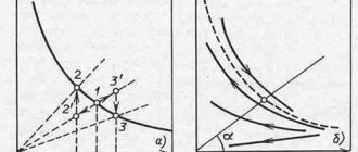
Current density affects arc voltage. This dependence is usually called the static characteristic of the arc (it is depicted graphically). Note that if the current density is small, then this characteristic can be decreasing: that is, a voltage drop occurs when the current, on the contrary, increases. This phenomenon is due to the fact that as the current value increases, the conductivity of electricity increases, as well as the cross-sectional area of the arc column, while the current density decreases.
When the current density usual for manual welding is used, the voltage loses its dependence on the current value. In this case, the area of the column increases in proportion to the current. Note also that the electrical conductivity remains virtually unchanged, and the current density in the column also remains constant.
ARC DISCHARGE
ARC DISCHARGE, independent quasi-stationary electrical discharge in gas, burning at almost any gas pressure exceeding 0.01–1 Pa (10–4–10–2 mm Hg), with a constant or varying low frequency (up to 103 Hz) potential difference between the electrodes. For D. r. characterized by a high current density at the cathode (102–108 A/cm2) and a low cathode potential drop, not exceeding the effective ionization potential of the medium in the discharge gap. For the first time D. b. between two carbon electrodes in the air was observed in 1802 by V. V. Petrov and independently of him in 1808 by G. Davy. The luminous current channel of this discharge, when the electrodes are horizontally positioned under the influence of convective flows, is bent in an arc shape, hence the names - D. r., electric. arc.
For the majority of D. r. at a high current density, a small, very bright spot appears on the cathode, moving over the entire surface of the cathode. The temperature in the spot can reach the boiling (or sublimation) temperature of the cathode material. Means. role in the mechanism of maintaining current D. r. Thermionic emission plays a role. A layer of positive space charge is formed above the cathode spot, which ensures the acceleration of emitted electrons to energies sufficient for impact ionization of atoms and gas molecules. Since this layer is very thin (less than the electron mean free path), it creates a high field strength at the cathode surface, especially near microinhomogeneities, therefore both field emission and thermal field emission are significant. The high current density and “jumping” of the spot from point to point create conditions for explosive electron emission.
From the zone of cathode potential drop to the anode there is the so-called. positive column. A bright anode spot usually forms on the anode, in which the surface temperature is almost the same as in the cathode. In some types of D. r. at currents of tens of amperes, torches appear on the cathode and anode in the form of plasma jets flying out at high speed perpendicular to the surface of the electrodes. At currents of 100–300 A, additional torches appear, forming a beam of plasma jets. Heated to a high temperature and ionized gas in the column is plasma. The electrical conductivity of a plasma can be very high, but it is usually only slightly higher. orders of magnitude lower than the electrical conductivity of metals.
When the concentration of charged particles is more than 1018 cm–3, the plasma state can sometimes be considered close to equilibrium. At lower densities, up to 1015 cm–3, a state of local thermodynamics may arise. equilibrium (LTE), when at each point of the plasma everything is statistical. distributions are close to equilibrium at one temperature value, which is different at different points. The only exception in this case is plasma radiation: it is far from equilibrium and is determined by the plasma composition and radiation rates. processes. With limited dimensions of the column D. r. even in dense plasma on the column axis, the LTE state is disrupted due to radiation. losses. This is expressed in a strong deviation of the plasma composition and the populations of excited levels from their equilibrium values. Kinetics of plasma in the column of D. r. at high densities it is determined mainly. collision processes, and as the density decreases (moving away from the axis), radiation plays an increasingly important role. processes.
Diameter of column D. r. determined by the conditions of the balance of emerging and lost energy. With increasing current or pressure, the loss mechanisms due to thermal conductivity of the gas, ambipolar diffusion, and radiation change. processes, etc. With such shifts, self-compression (contraction) of the column may occur (see Contracted discharge).
Depending on the combustion conditions of D. r. its parameters vary widely. Classic example D. r. – a direct current discharge burning freely in the air between carbon electrodes. Its typical parameters: current from 1 A to hundreds of amperes, distance between electrodes from millimeters to several centimeters, plasma temperature approx. 7000 K, anode spot temperature approx. 3900 K.
D. r. used as a laboratory light source and in technology (carbon arc lamps). D. r. with a carbon anode, drilled and filled with test substances, used in the spectral analysis of ores, minerals, salts, etc. D. r. used in plasmatrons, arc furnaces for smelting metals, electric welding, etc. electronic and lighting. devices T.n. a vacuum arc, which ignites in a vacuum and burns in metal vapor that has evaporated from the cathode, is used in vacuum high-voltage circuit breakers.
The nature of the phenomenon
The arc formation process is as follows:
- The welder touches the metal workpiece with the electrode for a split second.
- At the moment of contact, a short circuit occurs, accompanied by the flow of high current and, as a consequence, a powerful release of heat.
- The metal melts at the point of contact. It becomes viscous and viscous.
- At the moment the consumable is separated from the workpiece, a drop of melt trails behind it.
- Lengthening, it becomes thinner with the formation of the so-called. cervix. At some point, it evaporates and turns into a cloud of charged particles. At the same time, due to the high temperature in this zone, the air or shielding gas is ionized.
- Under the influence of an electric field, negative charge carriers rush to the anode, positive charge carriers - to the cathode. The process of current flow in the plasma begins.
At the moment of contact, a short circuit occurs and the metal at the point of contact melts.
Each stage lasts milliseconds, the discharge occurs almost instantly. The current is then maintained by the emission of electrons at the cathode. On their way to the anode, they ionize gas and metal vapor, increasing the number of free charge carriers.
Under what conditions does combustion begin?
An electric welding arc occurs at a current strength of 10 to 1000 A and a potential difference of 15-40 V. In cold air, ignition is difficult because it is weakly ionized. Under such conditions, the workpiece is heated or warm shielding gas is supplied.
Arc Power Supplies
To create a discharge, both direct and alternating voltages are used. In the first case, the weld is of higher quality, and the metal spatters less.
The current from the 220 V network is converted by a transformer, giving an output of 15-40 V.
In order to reduce its dimensions, modern welding machines use a circuit consisting of the following units:
- Input rectifier.
- An inverter is an electronic device with fast-switching transistors controlled by a microcircuit.
- Transformer.
- Output rectifier.
The inverter is the arc power source.
The inverter converts direct current into alternating current with a frequency of up to 80 kHz. This allows not only to reduce the size of the transformer, but also to increase the efficiency of the device.
The source parameters are selected taking into account the method of performing the work. For example, during manual welding, the arc length fluctuates, so you need a device with a steeply falling current-voltage characteristic. Thanks to it, the discharge does not go out when stretched, and when it is shortened, the current does not become too large.
When welding with a consumable electrode, drops of metal flow from it onto the workpiece. At such moments, a short circuit current occurs that exceeds the arc current by 20% -50%. It burns out the formed metal bridge, and the plasma discharge is formed again. These fluctuations occur in short moments of time, so the source must quickly respond to them, stabilizing the potential difference.
What and how power is determined
Plasma is a conductor with electric current flowing through it. This means that the question of how the power of a welding arc is determined is given the same answer as for any resistor: voltage and amperage. The rate of heat release is equal to the product of these quantities.
The power varies with the current strength, which depends on the length of the arc.
More often, the power is varied by the current strength, which, in turn, depends on the length of the arc. At the same time, the heating temperature of the metal changes, and with it the speed of work.
The meaning of the word arc discharge
arc discharge
discharge, one of the types of stationary electrical discharge in gases. It was first observed between two carbon electrodes in air in 1802 by V. V. Petrov and independently in 1808-09 by G. Davy. The luminous current channel of this discharge was arced, which gave rise to the name D. r. Formation of D. r. preceded by a short non-stationary process in the space between the electrodes - the discharge gap. The duration of this process (the time it takes to establish the discharge) is usually ~ 10-6-10-4 sec, depending on the pressure and type of gas, the length of the discharge gap, the condition of the electrode surfaces, etc. D. r. obtained by ionizing gas in the discharge gap (for example, using an auxiliary, so-called ignition electrode). In other cases, to obtain D. r. heat one or both electrodes to a high temperature or move the electrodes closed for a short time apart. D. r. may also occur as a result of breakdown of the electrical discharge gap during a short-term sharp increase in voltage between the electrodes. If the breakdown occurs at a gas pressure close to atmospheric, then the non-stationary process preceding the breakdown is a spark discharge. Typical parameters of D. r. For D. r. Characterized by the extreme variety of forms it takes: it can occur at almost any gas pressure - from less than 10-5 mm Hg. Art. up to hundreds of atm; potential difference between electrodes D. r. can take values from several volts to several thousand volts (high-voltage D. r.). D. r. can occur not only at constant, but also at alternating voltage between the electrodes. However, the half-cycle of an alternating voltage is usually much longer than the time it takes to establish the voltage, which makes it possible to consider each electrode as a cathode during one half-cycle, and as an anode in the next half-cycle. The distinctive features of all forms of D. r. (closely related to the nature of electron emission from the cathode in this type of discharge) are the small value of the cathode drop and the high current density at the cathode. Cathode drop in D. r. usually on the order of the ionization potential of the working gas or even lower (1-10 V); The current density at the cathode is 102-107 A/cm2. With such a high current density, the current strength in the D. r. usually also large - about 1-10 a and higher, and in some forms D. r. reaches many hundreds and thousands of amperes. However, there are also D. r. with a low current intensity (for example, a fire starter with a mercury cathode can burn at currents of 0.1 a and below). Electronic emission in D. rub. The fundamental difference between D. r. from other types of stationary electric discharge in gas lies in the nature of the elementary processes occurring at the cathode and in the near-cathode region. If secondary electron emission occurs in a glow discharge and negative corona discharge, then in D. r. electrons are ejected from the cathode in the processes of thermionic emission and field emission (also called tunnel emission). When in D. r. Only the first of these processes occurs; it is called thermionic. The intensity of thermionic emission is determined by the temperature of the cathode; therefore, for the existence of thermionic D. r. it is necessary that the cathode or its individual sections be heated to a high temperature. Such heating is carried out by connecting the cathode to an auxiliary energy source (Dr. with external heating; D.r. with artificial heating). Thermionic D. r. It also occurs when the temperature of the cathode is sufficiently increased by the impacts of positive ions formed in the discharge gap and accelerated by the electric field towards the cathode. However, more often with D. r. Without artificial heating, the intensity of thermionic emission is too low to maintain the discharge, and the process of field emission plays a significant role. The combination of these two types of emission is called thermal field emission. Field emission from the cathode requires the existence of a strong electric field at its surface. Such a field in D. r. is created by a volume charge of positive ions removed from the cathode at a distance of the order of the free path of these ions (10-6-10-4 cm). Calculations show that field emission cannot independently support the D. r. and is always, to one degree or another, accompanied by thermionic emission. Due to the difficulty of studying processes in a thin near-cathode layer at high current densities, experimental data on the role of field emission in D.R. Not enough has been accumulated yet. Theoretical analysis cannot yet satisfactorily explain all the phenomena observed in various forms of D. r. The relationship between the characteristics of D. r. and emission processes. The layer in which the electric field arises, causing field emission, is so thin that it does not create a large drop in the potential difference at the cathode. However, in order for this field to be strong enough, the volume charge density of the ions at the cathode, and therefore the ion current density, must be high. Thermionic emission can also occur at low kinetic energy of ions at the cathode (i.e., at a low cathode incidence), but under these conditions it requires a high current density - the cathode heats up the more, the greater the number of ions bombarding it. Thus, the distinctive features of D. r. (small cathode drop and high current density) are due to the nature of near-cathode processes. Plasma D. r. Discharge gap D. r. is filled with plasma, consisting of electrons, ions, neutral and excited atoms and molecules of the working gas and the substance of the electrodes. Average energies of particles of different types in plasma D. r. may be different. Therefore, when talking about the temperature of a electron, a distinction is made between the ionic temperature, the electron temperature, and the temperature of the neutral component. If these temperatures are equal, the plasma is called isothermal. Dependent D. r. D. r. is called dependent. with artificial heating of the cathode, since such a discharge cannot be maintained using its own energy: when the external heat source is turned off, it goes out. The discharge is easily ignited without auxiliary ignition electrodes. Increasing the voltage of such a D. r. first, it amplifies its current to a value determined by the intensity of thermionic emission from the cathode at a given filament temperature. Then, up to a certain critical voltage, the current remains almost constant (the so-called free mode). When the voltage exceeds the critical voltage, the nature of the emission from the cathode changes: the photoelectric effect and secondary electron emission begin to play a significant role in it (the energy of positive ions becomes sufficient to knock electrons out of the cathode). This leads to a sharp increase in the discharge current - it goes into a captive mode. Under certain conditions, D. r. with artificial heating continues to burn steadily when the voltage between the electrodes is reduced to values less than not only the ionization potential of the working gas, but also its lowest excitation potential. This form of D. r. called low voltage arc. Its existence is due to the appearance near the cathode of a maximum potential that exceeds the potential of the anode and is close to the first excitation potential of the gas, as a result of which stepwise ionization becomes possible (see Ionization). Independent D. r. Maintaining such D. r. is carried out due to the energy of the discharge itself. On refractory cathodes (tungsten, molybdenum, graphite) independent D. r. is purely thermionic in nature - bombardment with positive ions heats the cathode to a very high temperature. The substance of the low-melting cathode intensively evaporates during D. r.; evaporation cools the cathode, and its temperature does not reach values at which the discharge can be supported by thermionic emission alone—along with it, field emission occurs. Independent D. r. can exist both at extremely low gas pressures (so-called vacuum arcs) and at high pressures. Plasma of independent D. r. low pressure is characterized by non-isothermality: the ion temperature only slightly exceeds the temperature of the neutral gas in the space surrounding the discharge region, while the electron temperature reaches tens of thousands of degrees, and in narrow tubes and at high currents - hundreds of thousands. This is explained by the fact that more mobile electrons, receiving energy from the electric field, do not have time to transfer it to heavy particles in rare collisions. In D. r. high pressure plasma is isothermal (more precisely, quasi-isothermal, because, although the temperatures of all components are equal, the temperature in different parts of the plasma column is not the same). This form of D. r. characterized by significant current strength (from 10 to 103 A) and high plasma temperature (about 104 K). The highest temperatures in such a D. river. are achieved when the arc is cooled by a flow of liquid or gas - the current channel of the 'cooled arc' becomes thinner and, at the same current value, heats up more. It is this form of D. r. called an electric arc - under the influence of externally directed or convection gas flows caused by the discharge itself, the current channel of the D. r. bends. Cathode spots. Independent D. r. What distinguishes low-melting cathodes is that thermal field emission of electrons occurs in it only from small areas of the cathode - the so-called cathode spots. The small size of these spots (less than 10-2 cm) is due to the pinch effect - contraction of the current channel by its own magnetic field. The current density in the cathode spot depends on the cathode material and can reach tens of thousands of a/cm2. Therefore, intense erosion occurs in the cathode spots - jets of vapor of the cathode substance fly out of them at a speed of about 106 cm/sec. Cathode spots also form during D. r. on refractory cathodes, if the working gas pressure is less than approximately 102 mm Hg. Art. At higher pressures, thermal field emission D. r. with cathode spots moving chaotically along the cathode, it transforms into thermionic radiation. without cathode spot. Applications of D. r. D. r. widely used in arc furnaces for smelting metals, in gas-discharge light sources, in electric welding, and serves as a plasma source in plasmatrons. Various forms of D. r. occur in gas-filled and vacuum electric current converters (mercury rectifiers, gas and vacuum electric switches, etc.). D. r. with artificial heating of the cathode is used in fluorescent lamps, gastrons, thyratrons, ion sources and sources of electron beams. Ref.: Electric current in a gas. Steady current, M., 1971; Kesaev I.G., Cathode processes of the electric arc, M., 1968; Finkelnburg V., Mecker G., Electric arcs and thermal plasma, trans. from German, M., 1961; Engel A., Ionized gases, trans. from English, M., 1959; Kaptsov N. A., Electrical phenomena in gases and vacuum, M.-L.,1947. A.K. Musin.
Great Soviet Encyclopedia, TSB
What is an electric arc
This is one of the types of electrical discharge in gas (physical phenomenon). It is also called – Arc discharge or Voltaic arc. Consists of ionized, electrically quasi-neutral gas (plasma).
It can occur between two electrodes when the voltage between them increases or approaches each other.
Briefly about the properties: electric arc temperature, from 2500 to 7000 °C. Not a low temperature, however. The interaction of metals with plasma leads to heating, oxidation, melting, evaporation and other types of corrosion. Accompanied by light radiation, explosive and shock waves, ultra-high temperature, fire, release of ozone and carbon dioxide.
There is a lot of information on the Internet about what an electric arc is, what its properties are, if you are interested in more details, take a look. For example, in ru.wikipedia.org.
Now about my accident. It's hard to believe, but 2 days ago I directly encountered this phenomenon, and unsuccessfully. It happened like this: on November 21, at work, I was tasked with wiring lamps in a junction box and then connecting them to the network. There were no problems with the wiring, but when I climbed into the shield, some difficulties arose. It’s a pity I forgot my android at home, I didn’t take a photo of the electrical panel, otherwise it would have been more clear. Maybe I'll do more when I get back to work. So, the shield was very old - 3 phases, a zero bus (also known as grounding), 6 circuit breakers and a package switch (it seemed simple), the condition initially did not inspire confidence. I struggled with the zero bus for a long time, since all the bolts were rusty, after which I easily installed the phase on the machine. Everything is fine, I checked the lamps, they work.
Afterwards, I returned to the switchboard to carefully lay the wires and close it. I would like to note that the electrical panel was located at a height of ~2 meters, in a narrow passage, and to get to it, I used a stepladder (ladder). While laying out the wires, I discovered sparks on the contacts of other machines, which caused the lamps to blink. Accordingly, I pulled out all the contacts and continued inspecting the remaining wires (to do it once and not return to this again). Having discovered that one contact on the bag has a high temperature, I decided to extend it too. I took a screwdriver, leaned it against the screw, turned it, bang! There was an explosion, a flash, I was thrown back, hitting the wall, I fell to the floor, nothing was visible (blinded), the shield did not stop exploding and buzzing. I don't know why the protection didn't work. Feeling the falling sparks on me, I realized that I had to get out. I got out by touch, crawling. Having got out of this narrow passage, he began to call his partner. Already at that moment, I felt that something was wrong with my right hand (with which I was holding a screwdriver), I felt terrible pain.
Together with my partner, we decided that we needed to run to the first aid station. I don’t think it’s worth telling what happened next, I just got injected and went to the hospital. I will never forget this terrible sound of a long short circuit - itching with a buzzing sound.
Now I’m in the hospital, I have an abrasion on my knee, the doctors think that I was electrocuted, this is the way out, so they are monitoring my heart. I believe that I was not shocked, but the burn on my hand was caused by an electric arc that occurred during a short circuit.
I don’t yet know what happened there, why the short circuit occurred, I think that when the screw was turned, the contact itself moved and a phase-to-phase short circuit occurred, or there was a bare wire behind the package switch and an electric arc appeared when the screw approached. I'll find out later if they figure it out.
Damn, I went to get a bandage, they wrapped my hand so much that I’m writing with my left hand now)))
I didn’t take a photo without bandages; it was a very unpleasant sight. I don’t want to scare novice electricians….
So, let's move on:
General information about the electric arc
- home
- >
- Library
- >
- Steel production in chipboard
The priority for the discovery of the arc belongs to the Russian scientist academician Vasily Vladimirovich Petrov (1761–1834).
Petrov published the results of his experiments in 1803. He described the phenomenon of an arc in the atmosphere at normal pressure, as well as the oxidation of materials in the arc; recovery of metals from oxides (mixed with reducing agents - charcoal, lard, oils). The first information about the electric arc appeared in European literature in 1812.
Electric arc , or arc discharge, is one of the types of electrical discharges in gas or vapor. Gas is electrically neutral by nature, i.e. it consists of particles that have no electrical charge. For an electric discharge to pass through a gas, electrically charged particles - ions and electrons - must appear in the latter.
If charged particles appear in a gas due to some external influence on the gas and then an electrical discharge occurs, then such a discharge is called non-self-sustaining.
Ionization of the interelectrode gap can occur under the influence of short-wave radiation - ultraviolet, x-rays and gamma rays, as well as alpha, beta and cosmic rays.
If the appearance of charged particles in a gas is associated only with the presence of an electric field that causes a discharge, then such a discharge is called independent.
The voltage at which a self-sustained discharge is formed is called the ignition voltage or ignition potential. Its value depends on the properties of the gas and the product of the gas pressure p and the distance between the electrodes d. At a certain value p * d, the ignition potential reaches a minimum (Paschen's law), which is, for example, for air 330 V at p * d = 75.4 Pa-cm; at larger and smaller values of p * d, the ignition potential increases.
At atmospheric pressure, the ignition voltage is usually much higher than the minimum: for example, at d = 1 cm for air it is 3x10⁴ V.
Since there is always a certain amount of charged particles in the gas, an independent discharge can begin without an external ionizer when the voltage applied to the electrodes exceeds the corresponding ignition potential.
The arc arises and is maintained as a result of:
- emission of electrons from the cathode;
- accelerating them in an electric field;
- ionization of gases located in the discharge gap with the formation of ions due to collisions with accelerated electrons.
Electron emission from the cathode occurs:
- electrostatic or field electronic - emission of electrons under the influence of only a strong electric field at the cathode;
- thermionic – emission of electrons from the cathode as a result of the high temperature of the latter, which ensures an increase in the kinetic energy of the cathode electrons to a level exceeding the electron work function.
In metallurgical processes, both types of electron emission operate in the cathode region, but thermionic emission is predominant.
Arc discharges can be classified according to several criteria:
- by type of medium - arc in vacuum, in gas, in vapor (in the absence of vapors of substances, an arc discharge is possible at a pressure not lower than 10 mm Hg);
- according to external features - short arcs, long arcs.
Arcs are considered long if the electrodes between which it burns are so far away that the thermal state of one electrode does not affect the thermal state of the other. In electrometallurgy, arcs are long.
In an arc discharge, three structural regions can be distinguished - cathode, anode, and arc column (Fig. 1).
Rice. 1
Scheme of characteristic arc regions
Cathode region
– length approximately 10-7 m. Practically does not depend on the total length. It is formed as a result of the fact that electrons are more mobile than ions, and they are removed from the cathode region faster than positive ions reach it. Therefore, an uncompensated positive charge is formed in front of the cathode, which causes a cathode voltage drop.
The anode region is 10-5 – 10-6 m, on the order of the mean free path of an electron at atmospheric pressure. Here, practically no new charges arise, since the anode cannot emit heavy ions, therefore the transfer of charges is carried out by electrons coming from the arc column and an uncompensated negative charge is formed near the anode. This charge causes the anode voltage drop.
The arc column is the middle and longest part of the discharge; here the transformation of the main part of the electrical energy into thermal energy occurs. In chipboards, the arc column length ranges from 20 to 50 cm. The main source of particles is thermal ionization. In addition to ionization, recombination reactions occur in the column. In stationary mode, the arc column is electrically neutral. Since the speed of charged particles is proportional to their mass, the current in the column is transmitted mainly by electrons.
An arc discharge is characterized by a high current density (hundreds and thousands of A/cm2) and is possible only at certain gas pressures: at very low pressures (average vacuum p less than 0.1333 Pa (10-5 mm Hg)) - an arc discharge is impossible from - due to the lack of charge carriers, at very high pressures - the arc is impossible due to the increasing recombination of charges.
An electric arc column is a movable conductor that is easily deformed under the influence of magnetic fields. Therefore, the interaction of electric and magnetic fields in the working space of the furnace leads to the presence of the following magnetohydrodynamic effects: the pinch effect is the effect of compression of the arc column in the radial direction. The magnetic field formed around the arc column creates a compressive effect, which consists in the fact that when a current passes through the arc column, radial compressive forces arise, directed from the surface to the axis.
Blowing electric arcs in the direction opposite to the center of the furnace, i.e. towards the lining, typical for three-phase chipboards. This phenomenon is explained to a large extent by the interaction of the current flowing in the arc column and the current perpendicular to it in the liquid bath.
The indicated magnetohydrodynamic effects in practice lead to the appearance of circulation of metal and slag. The pressure and inclination of the arcs lead to the circulation of the metal, which accelerates the transfer of heat from the arc to the bath and promotes mixing of the metal and equalization of the temperature in it throughout the volume. The intense movement of metal and slag under the influence of electrodynamic forces covers a zone that is estimated at approximately 30% of the surface of the central part of the bath mirror.
The formation of a meniscus at the point of contact of the arc with the molten metal, which is caused by the pressure of the arc (due to the compressive effect) transmitted to the liquid slag and metal. In this case, the arc burns in the meniscus and its radiation to the side walls and the arch is shielded by metal and slag, the heat transfer from the arc directly to the metal increases. The higher the arc current, the more significant the effect.
The arc pressure on the metal F (H) is determined by the equation
F=5*10-8I2
(The arc pressure on the liquid metal at a current of 50 kA and an arc diameter of 5.7 cm will be equal to 125 N, which corresponds to the hydrostatic pressure of a column of liquid steel approximately 0.3 m high).
During the initial period of scrap melting, when the electrodes are lowered and there is a lake of liquid metal under them, it is important that a significant part of the heat emitted by the arc spreads into the scrap in the horizontal direction to avoid overheating of the hearth under the electrodes. This condition is realized when using an arc of greater length. As the direct threat of overheating the side walls of the furnace increases, the horizontal component of the heat flow should be reduced by shortening the arc and immersing it in the melt. In this case, the thermal effect of the arc should be directed downward into the bath. For this reason, if there is liquid metal in the furnace, it is preferable to work with a shorter arc.
- ← Section 2.2.4
- Section 3.2 →
Practical use
On an industrial scale, electric arcs are used for welding, plasma cutting, electric discharge machining, as an arc lamp in film projectors and in lighting. Electric arc furnaces are used to produce steel and other substances. Calcium carbide is obtained in this way because a large amount of energy is required to achieve an endothermic reaction (at temperatures of 2500 ° C).
Carbon arc lights were the first electric lights. They were used for street lamps in the 19th century and for specialized devices such as floodlights until World War II. Today, low pressure electric arcs are used in many areas. For example, fluorescent lamps, mercury vapor lamps, sodium vapor lamps and metal halide lamps are used for lighting, while xenon arc lamps are used for film projectors.
The formation of an intense electrical arc, similar to a small-scale arc flash, is the basis of explosive detonators. When scientists learned what a voltaic arc is and how it can be used, the variety of world weapons was replenished with effective explosives.
The main remaining application is high voltage switchgear for transmission networks. Modern devices also use sulfur hexafluoride under high pressure.
Literature
- Electric arc
- article from the Great Soviet Encyclopedia. - Spark discharge
- article from the Great Soviet Encyclopedia. - Raiser Yu. P.
Physics of gas discharge. — 2nd ed. - M.: Nauka, 1992. - 536 p. — ISBN 5-02014615-3. - Rodshtein L. A. Electrical devices, L 1981
- Clerici, Matteo; Hu, Yi; Lassonde, Philippe; Milian, Carles; Couairon, Arnaud; Christodoulides, Demetrios N.; Chen, Zhigang; Razzari, Luca; Vidal, François (2015-06-01). "Laser-assisted guiding of electric discharges around objects." Science Advances 1(5):e1400111. Bibcode:2015SciA….1E0111C. doi:10.1126/sciadv.1400111. ISSN 2375—2548.
Electric arc origin story
In 1801, the British chemist and inventor Sir Humphry Davy demonstrated the electric arc to his comrades at the Royal Society of London and proposed a name - electric arc. These electrical arcs look like jagged lightning strikes. This demonstration was followed by further research into the electric arc, shown by Russian scientist Vasily Petrov in 1802. Further advances in early electric arc research led to industry-leading inventions such as arc welding.
Compared to a spark, which is only instantaneous, an arc is a continuous electrical current that generates so much heat from the charge-carrying ions or electrons that it can vaporize or melt anything within the range of the arc. The arc can be maintained in DC or AC electrical circuits and must include some resistance so that the increased current does not go unchecked and completely destroy the actual source of the circuit with its consumption of heat and energy.
Arc discharge
The arc discharge was discovered by V.V. Petrov in 1802. This discharge is one of the forms of gas discharge, carried out at a high current density and a relatively low voltage between the electrodes (of the order of several tens of volts). The main cause of the arc discharge is the intense emission of thermionic electrons from the hot cathode. These electrons are accelerated by the electric field and produce impact ionization of gas molecules, due to which the electrical resistance of the gas gap between the electrodes is relatively small. If you reduce the resistance of the external circuit and increase the arc discharge current, then the conductivity of the gas gap will increase so much that the voltage between the electrodes decreases. Therefore, they say that an arc discharge has a falling current-voltage characteristic. At atmospheric pressure, the temperature of the cathode reaches 3000 C. Electrons, bombarding the anode, create a depression (crater) in it and heat it. The crater temperature is about 4000 C, and at high air pressures it reaches 6000-7000 C. The gas temperature in the arc discharge channel reaches 5000-6000 C, so intense thermal ionization occurs in it.
In some cases, an arc discharge is observed at a relatively low cathode temperature (for example, in a mercury arc lamp).
In 1876, P. N. Yablochkov was the first to use an electric arc as a light source. In the “Yablochkov candle” the coals were arranged parallel and separated by a curved layer, and their ends were connected by a conductive “ignition bridge”. When the current was turned on, the ignition bridge burned out and an electric arc formed between the coals. As the coals burned, the insulating layer evaporated.
The arc discharge is still used as a light source today, for example in spotlights and projection devices.
The high temperature of the arc discharge makes it possible to use it for the construction of an arc furnace. Currently, arc furnaces, powered by a very high current, are used in a number of industries: for the smelting of steel, cast iron, ferroalloys, bronze, for the production of calcium carbide, nitrogen oxide, etc.
In 1882, N. N. Benardos first used an arc discharge for cutting and welding metal. A discharge between a stationary carbon electrode and the metal heats the junction of two metal sheets (or plates) and welds them. Benardos used the same method to cut metal plates and make holes in them. In 1888, N. G. Slavyanov improved this welding method, replacing the carbon electrode with a metal one.
The arc discharge has found application in a mercury rectifier, which converts alternating electric current into direct current.
Varieties
There are several classifications of the element in question, which have different current supply schemes and the environment where it appears.
Welding
- With direct action. In this case, the equipment is installed parallel to the metal product that needs to be welded. The arc, in turn, becomes at right angles towards the electrodes and the metal surface.
- With indirect action. Appears when using two electrodes that are located at an angle of 50 degrees from the work being welded. An arc appears between the electrode and the material being welded.
The appearance of a welding arc.
In addition, it can be divided according to the principle of the atmosphere where the welding arc appears:
- Open sphere. The arc can burn in an open space with the formation of a gas phase, which contains vapor of the metal, electrode and surfaces after processing with a welding tool.
- Closed sphere. The arc burns under flux. In the gas phase near the arc, vapor from the material, electrodes and the flux layer itself enters.
- With supply of gas mixture. The arc may contain compressed gas such as helium, carbon dioxide, hydrogen, argon and other gaseous impurities. They are necessary so that the welded surface of the product is not subject to oxidation. Thanks to their supply, the environment is restored or becomes neutral to external factors. The gas supplied for operation, steam from the product being welded and the electrodes enter the arc.
In addition to the listed classifications, we can also distinguish types by duration of action:
- classic is used for constant use;
- pulse – for one-time use.
One of the most popular parts is steel, i.e. consumable electrode. However, today most professionals prefer non-melting, from which we can conclude that the types of elements under consideration are quite different from each other.
What are Foucault currents?
In a massive body, for example, a core (magnetic core) or a unit body, a volumetric current arises in the form of the movement of charged particles along circular (vortex-like) trajectories. This is called eddy currents.
A change in the magnetic flux crossing the conductor is observed in two cases:
- the conductor and the permanent magnet field move relative to each other. Example: the rotor core of an electric generator, in which the stator is a magnet (in many types the magnet is the rotor);
- There is no relative motion, but the magnetic field parameters change. To implement this option, an electromagnet (a wire wound into a coil) is used, through which alternating current is passed. Just like the current, the field will periodically change the direction of the field lines and the intensity of the magnetic flux (in antiphase with the current). Example: transformer magnetic circuit.
This phenomenon is called “Foucault currents” - in honor of the scientist J. B. L. Foucault, who did a lot of work on their study. The first to discover this phenomenon was the French scientist D. F. Arago, who in 1824 conducted an experiment with a copper disk and a magnetic needle rotating above it. The disk also began to perform similar actions. This effect began to be called in scientific circles the “Arago phenomenon.”
Magnetic field of Foucault currents
The researcher was unable to correctly explain the rotation mechanism; this was done a few years later by M. Faraday, who discovered EI:
- a flat round object is placed in a rotating magnetic field;
- its effect on the part is expressed in the induction of eddy currents in it;
- Foucault currents, in turn, interact with the magnetic field;
- the disk begins to spin.
The strength of eddy currents directly depends on the rate of change of magnetic flux.
Structure and zone of the anode spot
There are 3 sections in the structure of the arc:
- Cathode spot. It is the site of acceleration and emission of electrons and has a negative charge. The size of this zone is approximately 1 micron (0.001 mm). 38% of the heat is released here, the voltage drop is 12-17 V.
- Arc pillar. Has a neutral charge because positive and negative particles are present in equal quantities. The average length is 5-10 mm. In this area, 20% of the heat is released and 2-12 V is lost.
- Anode spot. Bombarded with electrons, which gives it a concave shape (crater). The length of this zone is 10 µm. 42% of heat is released, 2-11 V is lost.
Structure and properties of the electric welding arc.
Nature and structure
Structure and parameters of the welding arc.
In terms of its characteristics, the characteristics of the welding arc and its nature are quite easy to understand. The maximum temperature in the electrical element under consideration for welding can be up to 10 thousand degrees.
This is achieved by passing an electric current through the cathodes, where it enters the ionized gas, and then, after a discharge with a bright flash, makes it possible to warm up to the required temperature.
Afterwards, the current hits the metal, which is welded and further processed.
Since the temperature is quite high, this welding element emits infrared and ultraviolet rays, which are dangerous to the human body. This may impair vision or cause severe burns on the skin.
To protect yourself from negative consequences, you need to study its properties, characteristics, and also provide yourself or the master with reliable protection.
Another important aspect is the structure of the welding arc. The question of how many parts a welding element consists of is quite interesting and educational. First of all, it is worth noting that it has three main zones: anode, cathode and column.
When the mechanism on the cathode or anode burns, small spots appear - places where the temperature is maximum. Electric current flows through these areas, and the anodic and cathodic places on the surface imply a reduced voltage effect.
The pillar is often located in the middle of these locations, and the tension in it may subside slightly. Due to this, the welding element has a length that includes all of the listed areas.
Peculiarities
It has the following features compared to other electric charges:
- High current density, which reaches several thousand amperes per square centimeter, due to which very high temperatures are achieved;
- Uneven distribution of the electric field in the space between the electrodes. Near the electrodes the voltage drop is very high, when in the column it is the opposite;
- Huge temperature, which reaches the highest values in the column due to the high current density. As the length of the column increases, the temperature decreases, and when it narrows, on the contrary, it increases;
- Using welding arcs, you can obtain a wide variety of current-voltage characteristics - the dependence of the voltage drop on the current density at a constant length, that is, steady combustion. At the moment, there are three current-voltage characteristics.
The first is falling, when with an increase in strength and, accordingly, current density, the voltage drops. The second is hard, when a change in current does not affect the voltage value in any way, and the third is increasing, when as the current increases, the voltage also increases.
Thus, the welding arc can be called the best and most reliable way of fastening metal structures. The welding process has a major impact on today's industry because only the high temperature of the welding arc is capable of holding most metals together. To obtain high-quality and reliable seams, it is necessary to correctly and correctly take into account all the characteristics of the arc, monitor all values, thanks to this the procedure will be quick and most effective. It is also necessary to take into account the properties of the arc: current density, temperature and voltage.
DC arc discharge
Participation in the use of the method of finding the analyte in a light source when conducting chemical analysis.
DC arc discharge
An arc discharge is an independent electrical discharge in a gas, burning at almost any pressure exceeding 10-2-10-4 mm. rt. Art., with a constant or varying low frequency (up to 103 Hz) potential difference between the electrodes and characterized by a high current density at the cathode and a low cathode potential drop. During an arc discharge, the current at the cathode is contracted into a small, very bright cathode spot, moving randomly across the entire surface of the cathode.
The surface temperature in the spot reaches the boiling (or sublimation) temperature of the cathode material. Therefore, thermionic emission plays a significant (sometimes the main) role in the cathode mechanism of current transfer.
A layer of positive space charge is formed above the cathode spot, which ensures the acceleration of emitted electrons to energies sufficient for impact ionization of atoms and molecules of the medium.
Heated to a high temperature and ionized gas in the column is in the state of plasma. The released Joule heat replenishes all energy losses from the plasma column, maintaining its state unchanged.
For spectral and analytical purposes, a low voltage arc is predominantly used between carbon (graphite) electrodes (current is 5-15 A, supply voltage is 220 V, the current is limited by ballast resistance RB).
In spectral analysis methods, a direct current electric discharge is one of the first light sources. It has not lost its importance today and is widely used for qualitative and quantitative analysis of powdered materials - ores, minerals, highly pure substances, etc.
In a direct current arc, almost all elements are excited, with the exception of difficult-to-excite elements, for example, inert gases.
Figure 1 – DC arc diagram
Figure 1 shows a DC arc circuit. The ignited discharge is maintained by thermionic emission from the surface of the hot cathode. The voltage drop across the electrodes is usually 30–70 V and depends on many factors: electrode material, arc current, arc gap, atmospheric composition and pressure. The maximum voltage drop is observed when using carbon electrodes; the introduction of easily ionized elements into the arc discharge reduces the voltage. In operating mode, the strength of the current feeding the arc varies from several units to several tens of amperes, depending on the task.
When using a direct current arc, a portion of the sample is placed in the channel of an electrode made of carbon or graphite; evaporation of the substance occurs due to heat exchange between the electrode material and the substance. The temperature of the electrode depends on many factors: the thermal conductivity of the material, its configuration, the electrical parameters of the arc discharge and is determined by the overall power balance for the electrode.
The maximum arc temperature between carbon electrodes is about 7000 °K, between iron or copper electrodes – 5500 °K.
As already noted, the main mechanism of sample evaporation from the electrode channel is thermal vaporization of the substance as a result of heat transfer from the walls of the electrode to the sample. The kinetics of vaporization of elements is determined by the temperature of the electrode and the thermophysical properties of the sample. Evaporation is fractional in nature. Since the anode temperature is higher than the cathode temperature, the sample is most often evaporated from the anode channel.
A detailed study of fractional evaporation from the electrode channel made it possible to compile the so-called volatility series for elements in various chemical forms. This information is very important when analyzing samples of complex composition and using an arc as a light source.
Solid samples are introduced into the channel of the lower electrode, which is most often a rod of spectrally pure graphite. When the bottom electrode is connected to the positive pole of the current source, a particularly high temperature is obtained at its end, sufficient to evaporate even non-volatile compounds. Due to the good evaporation of the substances under study in a direct current arc, extremely high sensitivity of determination is achieved (which is especially valuable when analyzing traces) with more or less good reproducibility of measurement results. Liquid samples are introduced into the arc plasma in the form of an aerosol. Stabilized arc discharges can be used to quantify difficult-to-excite elements just as well as gas flames can be used to quantify easily excited elements.
A DC arc is an unstable light source. To stabilize it and achieve better metrological characteristics, various techniques are used:
Introduction of spectroscopic buffers and additives that allow you to change the temperature and evaporation rate of individual sample components.
Stabilization by blowing with inert gas, applying a magnetic field, etc.
The most effective use of a direct current arc is when determining small quantities of refractory compounds.
For a number of elements, the absolute limits of detection are 10-7–10-9 g, however, the determination error can reach 20–30%.
Arc Flash Injuries
When people think about arc flash injuries, they often assume that electric shock is the only risk. While electrocution is certainly a major hazard, it is really just the beginning of the potential problems. Below are some of the other ways electric arcing can harm people.
Burns - Even if the arc does not come into direct contact with a person, it can still cause a burn. Arc flash temperatures can reach 20,000 degrees Celsius, which can cause serious burns.
Fire. There is a danger of getting into fire. If there are any flammable items in the area, they should be removed.
Object Flying - An arc flash can create a lot of pressure that can send objects flying through the air. Things like molten metal and machine parts can become very dangerous projectiles.
Explosion Pressure – Pressure from an explosion can reach 2,000 pounds per square foot. This can throw people into the air. This is also what triggers the projectiles mentioned above.
Hearing damage - arc flashes are very loud. In fact, they can reach 140 dB in some cases. This is approximately the same sound level as a pistol shot. Because this happens quickly, it can cause serious hearing damage to those in the area.
Severity of potential injury
There are many ways an arc flash can cause injury to people and the surrounding area. The severity of the injury will depend on a number of factors. Understanding how dangerous the situation is can help agencies and employees properly prepare when entering an area where an arc flash is possible.
The following factors can affect how serious an injury may be:
Electricity. The force of electricity creating an arc flash will have a significant impact on potential injury. The higher the current, the greater the risk.
Proximity. The closer someone is to an actual arc flash, the more danger they are in
Therefore, it is important to keep people who are not trained and qualified to work on electrical equipment away from any area where there is the potential for an arc flash.
Length - The arc flash will usually continue until the circuit breaks. When the circuit breakers are working correctly, it only takes a split second. However, even a small increase in arc flash length can increase the likelihood of injury.
Temperature. Arc flash temperatures can also cause an increased risk of burns and other injuries.
Neighborhood. Objects in the area where an arc flash occurs can be a key indicator of the potential for injury. If an arc flash occurs around a warehouse, these objects can be thrown throughout the area, causing serious injury.
Area of influence. The location on the body where the arc hits also affects the potential for injury. While electricity itself can pass through the body from any entry point, the places where it enters and exits the body are susceptible to more severe burns.
Extinguishing the electric arc in switching equipment
Disabling elements of the electrical circuit must be done very carefully, without damaging the switching equipment. Opening the contacts alone will not be enough; it is necessary to properly extinguish the arc that occurs between them.
The processes of arc combustion and extinguishing differ significantly depending on the use of direct or alternating current in the network. If there are no particular problems with direct current, then with alternating current there are a number of factors to consider. First of all, the arc current passes the zero mark at each half-cycle. At this moment, the release of energy stops, as a result, the arc spontaneously goes out and lights up again. In practice, the current approaches zero even before crossing the zero mark. This is due to a decrease in current and a decrease in energy supplied to the arc.
Accordingly, its temperature decreases, which causes the cessation of thermal ionization. Intense deionization occurs in the arc gap itself. If at this moment you quickly open and route the contacts, then a breakdown may not occur, the circuit will turn off without the appearance of an arc.
In practice, creating such ideal conditions is very difficult. In this regard, special measures have been developed to accelerate arc extinction. Various technical solutions allow you to quickly cool the arc gap and reduce the number of charged particles. As a result, there is a gradual increase in the electrical strength of this gap and a simultaneous increase in the restoring voltage across it.
Both quantities are interdependent and affect the ignition of the arc in the next half-cycle. If the electrical strength exceeds the restoring voltage, the arc will no longer ignite. Otherwise, it will burn steadily.
Basic methods of arc extinguishing
Quite often the method of arc extension is used, when in the process of divergence of contacts when the circuit is disconnected, it stretches (Fig. 1). By increasing the surface area, cooling conditions are significantly improved, and a higher voltage is required to support combustion.
Application area
The welding arc is used in manual electric arc welding, which has become a reliable assistant for professionals and home craftsmen. Manual welding uses fusible electrodes coated with a flux compound. During the welding process, the rod material melts, forming the weld material, and the coating, when burned, releases a cloud of gases that protect the weld pool from exposure to oxygen. Manual welding is used both when working with conventional unalloyed structural steels and in unique welding operations on stainless, high-alloy alloys and non-ferrous metals.
The same arc is used in semi-automatic installations. Instead of an electrode, they use a welding wire fed by a mechanical device at a constant speed. Inert gases are pumped into the working area through the burner nozzle. This technology is characterized by optimal consumption of welding materials and high stability of weld parameters. Due to the high cost of the equipment, it is cost-effective for large volumes of welding work.
Automatic welding is carried out in special hermetically sealed volumes filled with inert gas. It is used for welding work with non-ferrous metals and especially critical operations with stainless alloys.
Tags: , machine, ampere, anode, sconce, throw, type, harm, switch, generator, house, , grounding, protective, pulse, like, , , magnet, power, voltage, neutral, variable, constant, potential, principle, wire, project, start, , work, size, resistor, row, garden, light, lamp, network, resistance, ten, type, current, transistor, transformer, , installation, phase, photo, shield, electricity, electrical panel, effect