One of the mandatory requirements for relay protection is the ability to back up individual protections in the event of their failure.
To do this, if the emergency mode is not switched off, the connection’s own protection must trigger another one. This other protection usually disconnects the section of the substation busbars to which the faulty feeder is connected. But to ensure selectivity, the shutdown will occur over a longer period of time, necessary to allow the feeder to disconnect from its own devices. During this time, a short circuit will cause great destruction and may increase in scale.
To speed up this process, one of the types of emergency automation is used - breaker failure protection. This abbreviation stands for “breaker failure backup device.”
Even a new and reliable switch controlled by a microprocessor relay protection device is not immune from malfunctions.
The causes of failures can be not only in its mechanics or in the welding of contacts. Trip circuits can also have problems that interfere with the command path from the output relay to the trip coil. But the list of possible problems does not end there. Sometimes the human factor is to blame for failures: choosing the wrong mode of operation of the protection, putting it out of action.
Watch an interesting video about the operation of a breaker protection system below:
Operating principle of breaker failure protection
The device is included in all modern microprocessor terminals, or is made separately for electromechanical protection. Its task is to issue a signal in the event of a failure, which is sent to the relay protection circuit of the upstream feeder.
For example, if there is a failure in the protection of the feeder leaving the substation buses, the breaker failure signal issues a shutdown command to the line switch supplying the bus section, as well as the sectional switch (if any).
It should be taken into account that in the disconnection circuits of the input and sectional switches, the disconnection signals from the breaker failure protection from all connections of the section fed by them are collected together.
In order for a breaker failure signal to be generated, the following events must coincide:
- tripping of the main feeder protection;
- continuation of the emergency process after the generation of a command to turn off its own circuit breaker, or the absence of a signal that the circuit breaker has turned off.
The logic of the breaker failure failure is extremely simple: a short circuit has occurred, causing the protection to start, a shutdown command has been sent, and the signal from the current transformers about the presence does not stop. This means that the switch does not turn off, or it was blocked by an electric arc.
An indispensable attribute of the breaker failure level is its own time delay.
It is counted between the moment the command to disconnect from the main protection is given and the command to the upstream circuit breaker. The shutter speed is short, but it is necessary to allow the mechanics to work, because any switch has its own shutdown time.
Principle and description of the operation of breaker failure protection.
The operation of the breaker failure protection depends on the primary connection diagram of the electrical installation.
Below are descriptions of the operation of the most common breaker failure protection circuits for substation with typical primary circuits of outdoor switchgear 110 - 500 kV.
1.2.1.For substations with single or double bus systems with fixed connection of elements, a common RUURV is provided for the entire system, performing the following functions:
1.2.1.1.In the event of a short circuit on the line or in a transformer (autotransformer) and failure to open the 110 (220) kV circuit breaker, the breaker failure acts on the output relays of the DZSh, which leads to the shutdown of the corresponding bus system.
1.2.1.2.In the event of a short circuit on the 110 (220) kV buses, the operation of the busbar protection and the failure of the line breaker, the breaker failure acts to stop the HF transmitter of the HF protection (if it is present on this line), which leads to the disconnection of the overhead line switch from the specified protection from the opposite side.
In addition, if there are organized maintenance channels in the power system, the breaker protection system generates a maintenance command with AR prohibition, and the UPASK equipment transmits it to the opposite end of the line, which also leads to the disconnection of the overhead line switch on the opposite side
1.2.1.3.In the event of a short circuit on the busbars, operation of the busbar protection (BPS) and failure of the transformer switch (autotransformer) with two- or three-way power supply, the breaker failure acts on the output protection relays of the transformer (autotransformer), which leads to the disconnection of the transformer (autotransformer) from all sides.
1.2.1.4.In the event of a short circuit on the buses, the operation of the busbar switch and the failure of the bus connection (sectional switch), the breaker failure acts on the output relays of the busbar system (section) of another bus system (section), which leads to its shutdown.
1.2.1.5.When a breaker failure occurs, the automatic reclosure of the circuit breakers of the bus system on which the connection with the failed circuit breaker is connected is prohibited (if at the enterprise the automatic reclosure is prohibited only in the event of a circuit breaker failure due to damage to transformers or autotransformers, then the text of this paragraph should be revised).
1.2.2.For switchgears with bridge circuits with three switches (switches towards the lines), a breaker failure common to the entire switchgear is provided, which performs the following functions:
1.2.2.1.In case of damage on the line and failure of the line switch, the breaker failure acts on the output protection relays of the transformer (autotransformer) with the 110 (220) kV switch disconnected in the jumper and with all transformer switches disconnected. In some cases, the breaker failure acts directly to trip circuit breakers without affecting the output relays of transformer protection.
1.2.2.2.If the transformer (autotransformer) is damaged and the line switch fails, the breaker failure acts on the HF transmitter of the main HF line protection with subsequent disconnection of the line from the opposite end.
If there are organized maintenance channels in the power system, the breaker failure device generates a maintenance command with AR prohibition, and the UPASK equipment transmits it to the opposite end of the line.
1.2.2.3.If the transformer (autotransformer) is damaged and the 110 (220) kV switch in the jumper fails, the breaker failure protection acts through the output protection relays of the transformer (autotransformer) to disconnect the second transformer (autotransformer) with complete shutdown of the substation.
1.2.2.4.When a breaker failure fails, the automatic reclosure of circuit breakers disconnected from the breaker failure at a given substation is prohibited (if the enterprise has adopted another option for prohibiting automatic reclosure, then this point should be revised).
1.2.3.For switchgears with bridge circuits with three switches (switches towards transformers), a common RUUROV is provided for the whole, performing the following functions:
1.2.3.1.In case of damage on the line and failure of the transformer switch, the breaker failure acts on the output protection relays of the transformer (autotransformer) with the 110 (220) kV switch disconnected in the jumper and with all transformer switches disconnected. In some cases, the breaker failure acts directly to trip circuit breakers without affecting the output relays of transformer protection.
1.2.3.2.If there is damage on the line and failure of the 110 (220) kV switch in the jumper, the breaker failure acts on the disconnection of the adjacent transformer (autotransformer) on the HV side and on the stop of the HF transmitter for HF protection of the undamaged line, followed by disconnecting it from the opposite end.
1.2.3.3.If the transformer (autotransformer) is damaged and the transformer switch fails, the breaker failure acts to disconnect the 110 (220) kV switch in the jumper and to stop the HF transmitter for HF line protection, followed by disconnecting the line from it from the opposite end.
If there are organized tele-shutdown (TO) channels in the power system, the breaker protection system generates a TO command with AR prohibition, and the UPASK equipment transmits it to the opposite end of the line, which also leads to a line shutdown.
1.2.3.4.When a breaker failure fails, the automatic reclosure of circuit breakers disconnected from the breaker failure at a given substation is prohibited (if the enterprise has adopted another option for prohibiting automatic reclosure, then this point should be revised).
1.2.4.For a switchgear with a quadrangle circuit, an individual breaker failure protection is provided on each switch, which performs the following functions:
1.2.4.1.If there is damage on the line and failure of one of the line switches, its breaker failure acts on the complete shutdown of the transformer (autotransformer) adjacent to the failed switch, through the output relays of its protections.
1.2.4.2.In case of damage in the transformer (autotransformer) and failure of one of the quadrangle switches, the breaker failure protection acts on:
— output relays of backup protection of the line that is adjacent to the failed circuit breaker, in which case the second line circuit breaker is turned off;
- stopping the HF transmitter of the HF protection of the above line, which leads to the disconnection of the line from the opposite side.
In addition, in this case, the breaker failure generates a tele-shutdown command with the automatic reclosure prohibited, and the UPASK equipment, if available, transmits it to the opposite end of the line, which also leads to its shutdown.
1.2.4.3.When a breaker failure fails, the automatic reclosure of circuit breakers that have tripped at a given substation is prohibited (if the enterprise has adopted another option for prohibiting autoreclose during the operation of a breaker failure, then the text of this paragraph is revised accordingly).
1.2.5.For a switchgear with a transformer - busbar circuit with an overhead line connected through two switches, an individual breaker failure is provided on each line, performing the following functions:
1.2.5.1.In case of damage on the line and failure of one of the breaker circuit breakers, the breaker failure acts through the output relays of the DZSh to disconnect all circuit breakers adjacent to the same bus system as the failed circuit breaker and, through the output protection relays of the transformer (autotransformer), on the circuit breakers of the MV and LV sides of the transformer ( autotransformer) rigidly connected to the same busbar system as the failed circuit breaker.
1.2.5.2.If there is damage in the transformer (autotransformer) or on the busbars and the failure of one of the line switches, the breaker failure acts through the output relays of the backup line protection to turn off the second switch of this line, as well as to stop the HF transmitter of the HF line protection of the same line, which leads to its shutdown with the opposite side.
In addition, in this case, the breaker failure generates a maintenance command with AR prohibition, and the UPASK equipment, if available, transmits it to the opposite end of the line, which also leads to disconnection of the line.
1.2.5.3.When a breaker failure fails, the automatic reclosure of circuit breakers that have tripped at a given substation is prohibited (if the enterprise has adopted another option for prohibiting autoreclose during the operation of a breaker failure, then the text of this paragraph is revised accordingly).
1.3. In order to carry out an additional attempt to eliminate the short circuit. at the connection, by disconnecting the connection's own breaker failure circuit, the breaker failure circuit provides for an instantaneous command to disconnect the failed circuit breaker directly from the breaker failure protection circuit (the so-called “self-acting”). To record this action, there are indicator relays in the breaker failure circuit, the operation of which occurs along with the operation of indicator relays from connection protection.
1.4. The response time of the breaker failure failure in all versions is 0.3 - 0.5 s.
1.5. In a switchgear with two bus systems, the breaker failure circuit is designed to work with rigid fixation of connections along the bus systems, therefore the breaker failure consists of two half-sets for 1 and 2 SB 110 (220) kV. Each half-set reserves the failure to disconnect the circuit breakers of those connections that are assigned to the corresponding bus system. If the fixation on the bus systems is violated, the breaker failure acts to disconnect all connections by combining the circuits of the 110 (220) kV DZSh output relays with the “DZSh without fixation on operational circuits” switch on the DZSh panel.
1.6. When any of the normally de-energized breaker failure relays are triggered and for a long time (several seconds) non-return, the circuit is automatically taken out of action with a light and sound signal indicating a breaker failure failure.
1.7. Interaction with other relay protection devices:
The breaker protection device interacts with relay protection devices of all connections and buses.
Interaction is organized according to the following chains:
- via breaker failure failure starting circuits equipped with switching devices in accordance with tables 1.5, 1.16
— on the output circuits of the breaker failure protection system, affecting the output relays of the auxiliary protection switch, on the output relays of transformer protections, on stopping the HF transmitters of the main line protections, generating a maintenance command with the prohibition of automatic reclosure on circuits equipped with switching devices in accordance with tables 1.3, 1.4.
1.8. Location and purpose of breaker failure protection panels
Table No. 1.1
| № | Panel purpose | Panel No. |
| Breaker level-220 kV | __R | |
| Level breaker level-110 kV | __R |
1.9. Operating current circuits
Table No. 1.2
| № | Designation according to the diagram | Location | Name |
| AB_ | __U (from the installation side) | Operating current breaker protection level - 220 kV. | |
| AB_ | __U (from the installation side) | Operating current breaker protection level - 110 kV. |
1.10. Signaling and switching devices Breaker level failure protection-220 kV panel No.___R
Table No. 1.3
| № | Designation according to the diagram | Name | Purpose |
| KN1 | Operation of breaker failure protection during a short circuit at the connection | Trigger signal for breaker failure protection in the event of a short circuit at the connection and failure of the circuit breaker | |
| KN2 | Operation of breaker failure protection during short circuit at I SSH-220 kV | Trigger signal for breaker failure protection in case of short circuit on I SS and circuit breaker failure | |
| KN3 | Operation of breaker failure protection during short circuit at II SSh-220 kV | Trigger signal for breaker failure protection in case of short circuit at II secondary level and circuit breaker failure | |
| KN4 | Breaker failure failure | Breaker failure failure signal | |
| SX1 | Shutdown I SSh-220 | Trip circuit I SS | |
| SX2 | Shutdown II SSH-220 | Trip circuit II SS | |
| SX3 | Shutdown 1T (AT)-220 | Shutdown circuit 1T(AT) | |
| SX4 | Disabling 2T (AT)-220 | Shutdown circuit 2T(AT) | |
| SX5 - SX8 | Reserve | Reserve | |
| SX9 | Breaker failure failure input | Putting the breaker breaker into operation |
1.11. Signaling and switching devices UROV-110 kV panel No.___R
Table No. 1.4
| № | Designation according to the diagram | Name | Purpose |
| KN1 | Operation of breaker failure protection during a short circuit at the connection | Trigger signal for breaker failure protection in the event of a short circuit at the connection and failure of the circuit breaker | |
| KN2 | Operation of breaker failure protection during short circuit at I SSh-110 kV | Trigger signal for breaker failure protection in case of short circuit on I SS and circuit breaker failure | |
| KN3 | Operation of breaker failure protection during short circuit at II SSH-110 kV | Trigger signal for breaker failure protection in case of short circuit at II secondary level and circuit breaker failure | |
| KN4 | Malfunction UROV-110 | Breaker failure failure signal | |
| SX1 | Shutdown I SS | Trip circuit I SS | |
| SX2 | Shutdown II SS | Trip circuit II SS | |
| SX3 | Shutdown 1T (AT) -110 | Shutdown circuit 1T(AT) - 110 | |
| SX4 | Shutdown 2T (AT) -110 | Shutdown circuit 2T(AT) -110 | |
| SX5 - SX8 | Reserve | Reserve | |
| SX9 | Breaker failure failure input | Putting the breaker breaker into operation |
1.12. List of protections (lines, transformers, buses), when taken out of service, the 220 kV breaker failure protection circuit must be taken out of service.
Table No. 1.5
| № | Name of connection | Protection | Panel No. | Name of pads |
| VL-220 “PS A” | DFZ-201 | __R | N 5 “Start UROV-220” | |
| Distance protection | __R | N ... “Start UROV-220 from distance protection” | ||
| MFTO | __R | N... “Start-up UROV-220 from MFTO and TZNP” | ||
| TZNP (ground protection) | ||||
| 1AT | Basic protection and side protection 220 kV T (AT) | __R | N__ "Start UROV-220" | |
| … | … | … | … | |
| I SSH-220 | DZSHT-I SSH | __R | N28 “Start UROV-220” | |
| II SSH-220 | DZShT-II Secondary School | __R | N29 “Start UROV-220” |
1.13. List of protections (lines, transformers, buses), when taken out of service, the 110 kV breaker failure protection circuit must be taken out of service.
Table No. 1.6
| № | Name of connection | Protection | Panel No. | Name of pads |
| VL-110 “PS S” | DFZ-201 | __R | N 5 “Start UROV-110” | |
| Distance protection | __R | N ... “Start UROV-110 from distance protection” | ||
| MFTO | __R | N... “Start-up UROV-110 from MFTO and TZNP” | ||
| TZNP (ground protection) | ||||
| 1AT | Basic protection and side protection 110 kV T (AT) | __R | N__ “Start UROV-110” | |
| … | … | … | … | |
| I SSh-110 | DZSHT-I SSH | __R | N28 “Start UROV-110” | |
| II SSh-110 | DZShT-II Secondary School | __R | N29 “Start UROV-110” |
Breaker failure protection circuits on an electromechanical basis
To implement the breaker failure failure algorithm based on electromechanical relays, several methods are used.
The simplest one: the output protection relay triggers a relay that counts the breaker failure delay.
An overlay is installed in this circuit to disable the automation. The closed contacts of the time relay generate a shutdown command.
This scheme is not widely used due to insufficient reliability. Too many factors can lead to its false alarm.
A reasonable way out of this situation is to add a node to the circuit that monitors the presence of a short circuit in the network. The simplest option is to install a voltage relay. It closes its contacts in the circuit when the line voltage decreases or reacts to its positive or reverse sequence. But sometimes it does not feel significant changes during a short circuit behind transformers.
Automation with control of the connection current works more efficiently.
The signal is formed when two factors coincide: the protection of the output relay is triggered and the presence of current through the switch, controlled by an additional current relay.
To further increase reliability, contacts are included in the breaker failure circuit that disable it when operating the control key. An additional circuit for shutting down the own circuit breaker using the breaker failure command is also introduced, independent of the circuit breaker circuits for protection.
In the event of incorrect actions of the breaker failure protection, this sometimes allows you to avoid large-scale outages, limiting yourself to false tripping of the circuit breaker of your connection.
But the influence of the human factor on false actions of the breaker protection device is difficult to exclude. If the overlay is not removed (the shutdown circuit is open), then when checking or testing the relay protection, a situation may arise when a shutdown pulse is nevertheless generated.
Backup device in case of breaker failure
- home
- Relay protection
- Level of failure
First, let's decipher what the mysterious abbreviation UROV means.
Breaker failure protection means a backup device in the event of switch failure. It is used on high voltage power lines from 35 kV and above. In relay protection, the concepts of short-range and long-range redundancy are used. Let me briefly remind you what it is.
With short-range redundancy, if the protections of a damaged element fail to operate, the damage is eliminated by the action of other protections of this element, and with long-range backup, by the action of protections of adjacent elements.
So the breaker failure rate refers to short-range redundancy. The principle of operation of the breaker protection on the fingers can be explained as follows:
- line B1 switch fails
- with a time delay T* the protection is triggered
* T consists of the time necessary to prevent the flow of short-circuit current during normal operation of the switch (it should be slightly longer than the switch-off time). Or more precisely from the return time of starting protections, relays, reserve time, switch off time taking into account arc extinction, relay scatter time;
- The protection switches off adjacent connections through which the short-circuit point can be fed. In the example, these are switches B2 and B3
- – Redundancy device for failure of 35-500 kV circuit breakers. “Guidelines for relay protection. Issue 6". Already 1966.
- – I.R. Taubes - Redundancy device in case of circuit breaker failure (CBF) in 110-220 kV networks (Electrician's Library, issue 608) - 1988
- – Rubinchik V.A. – Redundancy for shutting down short circuits in electrical networks.
The protection is duplicated by the second set, which reserves the first. The protections are made independently and are powered from different opercurrent circuits through separate CTs and are made with different relays. This is necessary so that the failure of one set of protection does not lead to the shutdown of the second set.
The advantage of breaker failure over long-distance backup is that breaker failure requires fewer shutdowns, which has a positive effect on reliability.
In addition, the breaker failure protection is performed directly on the protection of the element itself, therefore it is highly sensitive.
However, breaker failure circuits are quite complex, since they contain many relay circuits and control circuits for all switches involved in the circuit. Therefore, false alarms are possible, including due to the actions of personnel. Such accidental operations can lead to serious consequences, therefore, serious reliability requirements are imposed on breaker failure protection systems.
More detailed information on typical breaker failure protection circuits and operating principles can be found in the following literature:
AVR in everyday life and at work
Breaker failure failure as part of microprocessor devices
By default, modern relay protection terminals contain breaker failure protection. Whether or not to include it is a design decision made for a specific application.
In the terminal's breaker failure protection settings, all the configuration necessary for its operation is selected, including time and current control settings.
Since all protections are collected in one housing and interconnected, the operation of the automation becomes more reliable. There is only one problem left: it is mandatory to remove the breaker failure protection device from operation before checking the protection by electrical laboratory personnel. When checking the tripping and reset settings of any protection, the current corresponding to the emergency parameter exists at the terminal input for a long time, which is more than enough to generate a breaker failure signal.
Therefore, the repair and commissioning of devices containing emergency automation must be carried out according to pre-designed programs.
ads
Greatping writes:
1. One eminent relay operator is definitely sure that in addition to Obagley’s remark (kudos to him), the main function is to turn off one circuit breaker, and not half of the substation, in the event of a false start of the breaker failure. there is a second main function - to reserve the failure of protections associated with their erroneous output - the exploded 3xAODTSTN at Arzamas 500 kV is a mute confirmation of this - therefore action on oneself is necessary.
Unfortunately, as scorp correctly noted, the action to disconnect and start the breaker failure protection must be input/output by different switching devices in the protection cabinets. Only then will the breaker circuit breaker be able to reserve the personnel error. But not all projects have such devices in the breaker failure protection circuit. There are cases when the breaker failure circuits as part of the ACU are generally hard-wired, without keys. On the one hand, it’s good, you won’t lose the effect, on the other hand, hemorrhoids during maintenance. In general, you need to look at design decisions very carefully and weigh the pros and cons. And all the difficulties are due to the fact that currently there are no standard projects for URZA based on MP terminals. Nobody wants to do this work and take responsibility.
Greatping writes:
2. Answering the question from the experienced Bogatikov: We had a case in Dagestan when one of the switches of a 330 kV overhead line was turned off solely by the action of the breaker failure on itself. Calculated by chance. And why introduce a delay in the operation of the breaker failure protection system on yourself? Answer: To calculate it at the first shutdown and not by chance.
Do you mean that the delay in the action of the breaker failure protection on itself would help to calculate? Perhaps, but when information passes through dispatch channels that everything is working normally (not a single operative will notice a delay of 100-150 ms), no one carefully analyzes the oscillograms. In this situation, there was an overlap of several factors and the overall picture could only be clarified after connecting the overhead line protection and breaker failure switches to PARMA using analog and discrete signals.
Greatping writes:
4. Setting I< breaker failure, Ic max, t breaker failure are closely related. You can have t LEV < 100ms but then I< LEV should be >0.05 I kzmax. The constant is empirical, I think Obagley can offer a more reasonable value
grsl writes:
The choice of current level for breaker failure is of course related to time t1
This is what I didn’t understand, what is the connection between current and time? More? The time depends on the technical characteristics of the primary and secondary equipment, and the current is selected for AT, T, overhead lines 110, 220 kV based on sensitivity to short circuit. For overhead lines 330 and above - according to detuning from capacitive currents. Ideally, the breaker failure protection system should include capacitive compensation. This condition is fulfilled only by PDE-2005 and SHE2710 511. In the last settings that we issued for the breaker failure protection in S60, we generally had to sacrifice sensitivity to short circuit on the LV AT side for the sake of detuning from the capacity of a 500 kV overhead line (more than 400 km). At the same time, as part of the main AT protections, it was necessary to install an analogue of the LV breaker failure with start-up from the main AT protections, control of the HV current and the on position of the HV switches.
grsl writes:
so the minimum time settings: t1>tcb+tv+tmargin=40ms+19ms+20ms>79ms
Why do you need to incur such difficulties in Urov?
grsl writes:
1. Level of failure from no-current protection (for example, gas protection, or reverse power protection of a generator); what will be the current settings?
For gas, none, because it reacts to turn faults, and this is not the design mode. What is reverse generator power?
grsl writes:
2. Start the breaker failure protection - and at what constant should we do the boom? 3. What is the permanent position of the AUV?
What do you mean, power supply via operational circuits?
grsl writes:
4. Why is the breaker failure level at 150ms if the system can’t handle 200-250ms?
Of course he does. But a calculation is a calculation. If he allows it, why wait longer? For four years with such settings, there was not a single hint of improper operation. I'll knock on the wooden head. On the other hand, if you believe the calculations of the regime operators, during a short circuit at a nuclear power plant outdoor switchgear, the stability of the units is disrupted after 100 ms. In this case, a reasonable reduction in breaker failure time is justified.
Relay protection of electrical networks 110-220 kV.
The reliability of disconnecting a short circuit on an overhead line is ensured by both the reliability of the operation of the overhead line protection and the reliability of the disconnection of the overhead line switch. Reliability of operation of overhead line protection is ensured by short-range protection redundancy. But no matter how many protections work on the overhead line, if the overhead line switch fails, the damaged overhead line will still not turn off. In this case, long-range backup protection will work.Disadvantages of long-range backup protection in case of failure of an overhead line switch:
1. Extinguishing the entire 110-220 kV outdoor switchgear, from which the damaged overhead line with a failed switch originates. Protections at 110-220 kV SHSV are usually disabled, so at simple step-down substations the SHSV is not turned off in this case, which leads to the extinguishing of both substation bus systems. To disconnect the busbar system and thereby preserve one bus system in operation at large substations and power plants, the following is used: backup protection of (auto)communication transformers and generator-transformer units operate with two time delays: with the first time delay the busbar system is turned off, with the second - (automatic) )coupling transformer or generator-transformer unit.
2. Redemption of tapping PS.
3. If the short circuit on the overhead line is stable, then voltage is re-applied to it in turn by the automatic reclosure devices of all supplying overhead lines.
4. The difficulty of restoring the normal network diagram after eliminating a short circuit, since switches were disconnected at many substations.
5. Long total short circuit elimination time (several seconds), since with long-range backup, 3-4 stages of backup protection usually operate. If, under conditions of long-range redundancy, the protections operate in cascade, then the total time to disconnect the short circuit can reach several tens of seconds.
6. The sensitivity of protection for long-range redundancy is not always sufficient - there is no long-range redundancy.
All these disadvantages are eliminated if a special device for reserving circuit breaker failures (CBF) is used at the substation. The breaker failure failure is designed to quickly disconnect switches adjacent to the failed one. Principle of operation of the breaker failure protection system: if the protection acting to open the circuit breaker has been triggered, and the current through the circuit breaker does not stop within a specified time, then the breaker failure failure system disconnects all circuit breakers adjacent to the failed one with automatic reclosure prohibited.
Initially, breaker failure protection was used only at power plants and large, responsible substations. Nowadays, a breaker protection system is installed at almost every 110-220 kV substation that has a double SS and even at a substation with a simplified outdoor switchgear circuit (bridge).
To perform a breaker failure failure on a substation, in addition to the breaker failure failure itself, you must do the following:
1. All protections that act on tripping the circuit breakers must have 2 output contacts: one contact - on tripping the circuit breaker, the second contact - on starting the breaker failure protection (so that the breaker failure protection system knows that the protection has acted on tripping the circuit breaker, and that the circuit breaker must be turned off).
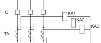
2. A special current relay is installed on each switch, which monitors the presence of current through the switch for the breaker failure protection (Fig. 5.16.1). A three-phase current relay of type RT-40/R has been developed specifically for breaker failure protection, which is triggered when there is current in one, two or three phases. Current relays for breaker failure protection are installed on all standard backup protection panels of 110-220 kV overhead lines: EPZ-1636, ShDE-2801(2), ShE2607 011, 012, 016, 021, 022.
The breaker failure failure time delay is usually taken to be 0.3-0.4 seconds. During this time, the switch should have time to turn off.
Switch failure redundancy device (CBF)
Breaker failure redundancy devices (CBF) are designed to disconnect with a short time delay the circuit breakers of all substation connections feeding the short circuit in the event of a failure to disconnect from the protection of one of the circuit breakers controlled by this breaker failure. The breaker failure can be bus or linear. The following conditions are required for the breaker protection system to operate:
— the effect of protection on tripping the circuit breaker;
- failure of the switch to turn off;
— presence of current in the circuit of the failed switch.
Switch failure backup devices are installed, as a rule, complete with differential busbar protection (DBP) or differential busbar protection (DBP). When the line protection is operating and the breaker failure circuit breaker fails, through the DZSh circuit it acts to disconnect all connections of the bus system with automatic reclosure prohibited. When the DPS is operating and the circuit breaker of one of the lines fails, in the presence of high-frequency protection of the line, the breaker failure operates to stop the HF transmitter of the corresponding line to disconnect the line from the opposite end. If emergency automatics equipment is available, the breaker failure protection circuit operates in the emergency automatics circuit to transmit a command to disconnect the line from the opposite end with automatic reclosure prohibited. When the DPS is operating and the circuit breaker of one of the transformers fails, the breaker failure protection acts to disconnect adjacent sides of the transformer with automatic reclosure prohibited.
Effect of breaker failure at substations with a double bus system (bus breaker failure).
For the correct operation of the breaker failure protection system at these substations, it is necessary to adhere to strict fixation of connections on busbar systems (as for DZSh).
In case of replacement of a circuit breaker of any connection with a bypass switch, the current circuits are replaced and the position of the replaced circuit breaker and its protections in the circuit breaker failure circuit on the circuit breaker failure protection and its protection are monitored, ensuring the correct operation of the circuit breaker failure in the event of failure of the circuit breaker and the disconnection of the circuit breaker from the circuit breaker failure.
Let's consider the operation of a bus breaker failure protection system using the example of outdoor switchgear-110 of a state district power plant (Figure 2-5).
The breaker failure circuit with a short time delay (0.3 - 0.5) seconds acts on tripping and prohibiting automatic reclosure of adjacent circuit breakers. Some breaker failure circuits provide repeated tripping of a failed circuit breaker with a time delay. Algorithm for the action of breaker failure protection on adjacent switches:
— when the protection of outgoing lines, AT or generators is operating and the linear circuit breaker is not disconnected, a command is issued through the output relays of the DZSh to disable all circuit breakers of the bus system behind which the failed circuit breaker is located, and through additional output relays to prohibit the automatic reclosure of the corresponding circuit breakers;
— when the DZSh is operating and the outgoing line switch equipped with UPASK fails (section “Channels of emergency automatics and devices for transmitting emergency signals and commands”), it acts on the start of command No. 1 (tele-shutdown with AR prohibition) to disconnect the line from the opposite end;
— when the DZSh is operating and the switch of the outgoing line equipped with the main high-speed double-acting protection (DFZ or DZL) fails, it acts to stop the HF transmitter DZL or undermine the connecting wires of DZL-2 to disconnect the line from the opposite end;
— when the DPS is operating and the AT switch fails, through the output relays of the main protections of the autotransformer, it acts to turn off the AT from all sides with the automatic reclosure prohibited;
— when the closed circuit breaker of one bus system is operating and the ShSV-110 fails, it acts to disconnect all switches of the adjacent bus system and to prohibit the automatic reclosure of the corresponding switches.
The breaker failure circuit is started when the output protection relays of each connection are activated with control of the connection switch current. The operation of the output protection relay with the continuation of current flow through the circuit breaker beyond the normal shutdown time is a sign of circuit breaker failure.
The breaker failure circuit provides for monitoring the position of intermediate relays that ensure the operability of the device. If the relay position does not correspond to a serviceable breaker failure circuit, a fault signal is issued with a short time delay, the breaker failure is automatically taken out of operation and blocked.
If the connection is an overhead line that is equipped with a DFZ, the breaker failure additionally stops the HF transmitter of the DFZ of this line and, therefore, ensures quick disconnection of the line from the opposite end. When the DZSh operates and there is a refusal to turn off the transformer switch (or AT), the breaker failure protection switches off the transformer (AT) switches of other voltages, eliminating the feeding of the short circuit on the busbars through the transformer (AT).
In addition, the breaker failure circuit also disconnects the remaining connections of the bus system to which the failed transformer switch (AT) is connected. When the DZSh operates and there is a refusal to disconnect the ShSV, the breaker failure protection circuit, through the DZSh circuit, disconnects all connections of the undamaged bus system with the automatic reclosure prohibited.
Additional information related to the specifics of terminology is on the Breaker Failure Protection page. Features of terminology
[ Back ][ Home ][ Up ][ Next ]