Torque of asynchronous electric motor
The equivalent circuit of an asynchronous electric motor, discussed in the previous article, makes it possible to obtain an expression for the electromagnetic torque that an asynchronous electric motor develops. The power consumed by an electric machine from the network will be spent not only on useful work, but also on losses in the magnetization circuit and in the windings.
Therefore, the power expression will look like:
Based on formula (1), we can obtain the following equation:
In turn, electromagnetic power can be expressed in this way:
From the above equations we can obtain the value of the electromagnetic torque:
By multiplying the denominator and numerator of this expression by S2 and in order to simplify the form of the equation, we take the value Xk = X1 + X2/. Xk – inductive resistance of an asynchronous electric motor during a short circuit:
To simplify the notation, as in equality (5), the index “um” will be skipped.
The electromagnetic torque of an asynchronous machine is a rather complex sliding function S. In order to find the maximum torque of an asynchronous machine, we equate the derivative of S to zero:
The derivative will become equal to zero only if the factor in the numerator brackets is equal to zero:
Or:
Where can we express sliding:
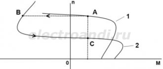
Sк is called critical, since during the transition S = Sк the engine torque will decrease. This is due to the fact that with an increase in the rotor current (S > Sk), its active part will not increase, but, on the contrary, will decrease, which in turn will lead to a decrease in torque.
If Sk is positive, this is the motor operating mode, and if negative, this is the generator operating mode.
In high-power asynchronous machines, r1 is significantly less than Xk, and, as a rule, lies in the range r1 = 0.1 - 0.12 Xk. Therefore, the value of r12 is significantly small compared to Xk, and it can be neglected without compromising accuracy:
Substituting positive values of Sk (6) into expression (5), we find the value of the critical moment for the motor mode:
Opening the brackets in the denominator (8) and reducing the fraction to the value Mkd we get:
For high-power machines for which the value of r1 can be neglected, expression (9) will take the form:
The value of the critical moment for the generator mode is obtained in a similar way:
The ratio of the moments of the generator and motor modes of operation of the IM:
Dividing the numerator and denominator by and denoting the ratio, expression (12) takes the form:
ε can also be expressed as:
Since asynchronous electric motors usually have r1 ≈ r2/, we can approximately assume:
From expressions (12) and (13) one can see that in the generator mode the value of the critical moment will be greater than in the motor mode. This is explained by the influence of the voltage drop in the active resistance of the stator winding.
The ratio of the electromagnetic torque to its critical value in the motor mode Mdk = Mk will have the form:
From where we express:
This expression is a refined equation for the mechanical characteristics of an asynchronous electric motor.
If we accept, as was done above, r1 = 0, then ε = 0 and instead of (15) we obtain a simplified equation for the mechanical characteristic:
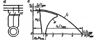
M, expressed by formulas (5), (15) and (16), is a function of slip S. By specifying different values of slip S, it is possible to construct a mechanical characteristic of an asynchronous machine.
The mechanical characteristic constructed according to formula (15) is shown below:
For asynchronous three-phase machines with a squirrel-cage rotor of general use with a power of 0.6 - 100 kW, the ratio should lie in the range of 1.7 - 2.2; wherein the larger value corresponds to a higher rotor speed of 3000 rpm, and the smaller value corresponds to 750 rpm. For machines with power over 100 kW, they should have λm = 1.7 - 1.8. For crane and metallurgical plants:
Equations (15) and (16) have a significant advantage over equation (5) in that there is no need to know the parameters of the windings of an asynchronous machine and calculations can be made using the catalog data of the electric motor.
But in the catalog data the value of the critical slip is not given and they have to be determined from relations (15) and (16), using the values of the overload capabilities of the machines λm.
Having written the equation of the mechanical characteristic for Mnom, we obtain:
Using the approximate equality ε ≈ Sк, we obtain:
This equality can be represented as a quadratic equation with respect to Sк:
Having solved it:
In high-power electric motors ε ≈ 0 and the equation for Sк will take the simpler form:
In expressions (17) and (18), a plus sign should be taken before the root, since a negative sign corresponds to the location of the point Snom, Mnom on the mechanical characteristic in the zone where S>Sк. This case has no practical application, so the second solution is discarded.
The above mechanical characteristics (5), (15), (16) are valid only under the restrictions stated above. Asynchronous electric motors with a wound rotor have characteristics quite accurately described by these equations. In machines with a squirrel-cage rotor, there is a process of displacement of current in the rotor rods. The consequence is that their parameters are inconsistent and their mechanical characteristics may differ significantly from those constructed using formulas (5), (15), (16). However, this does not make these formulas (especially (15), (16)) lose their significance, since due to their simplicity they allow many calculations to be made and general conclusions to be made about the operation of asynchronous machines. In cases where greater accuracy is required, experimentally measured or specially calculated mechanical characteristics are used.
As an example, the mechanical characteristics of some types of electric motors with a short-circuit rotor are shown below:
Related materials:
- How a Microstepping Controller Provides Smoother...
Work and power
If we're talking about rotation, power is expressed as torque (T) multiplied by speed (w).
The rotational speed of an object is determined by measuring the time it takes for a certain point on a rotating object to complete a full rotation. Typically this value is expressed in revolutions per minute, i.e. min-1 or rpm. For example, if an object makes 10 complete revolutions per minute, that means its rotation speed is: 10 min-1 or 10 rpm.
So, rotation speed is measured in revolutions per minute, i.e. min-1.
Let's bring the units of measurement to a general form.
For clarity, let's take different electric motors to analyze in more detail the relationship between power, torque and speed. Although the torque and speed of electric motors vary greatly, they can have the same power.
For example, let's say we have a 2-pole motor (3000 rpm) and a 4-pole motor (1500 rpm). The power of both electric motors is 3.0 kW, but their torques are different.
Thus, the torque of a 4-pole electric motor is twice the torque of a two-pole electric motor with the same power.
How are torque and speed generated?
Now that we've covered the basics of torque and speed, we need to look at how they are created.
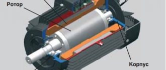
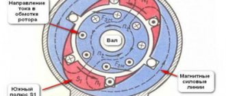
In AC motors, torque and speed are created by the interaction between the rotor and the rotating magnetic field. The magnetic field around the rotor windings will tend to the magnetic field of the stator. In real operating conditions, the rotor speed always lags behind the magnetic field. Thus, the magnetic field of the rotor crosses the magnetic field of the stator and lags behind it and creates a torque. The difference in the rotational speed of the rotor and stator, which is measured in %, is called the sliding speed.
Slip is the main parameter of an electric motor, characterizing its operating mode and load. The greater the load the electric motor must handle, the greater the slip.
Keeping in mind what was said above, let’s look at a few more formulas. The torque of an induction motor depends on the strength of the magnetic fields of the rotor and stator, as well as on the phase relationship between these fields. This relationship is shown in the following formula:
The strength of the magnetic field primarily depends on the design of the stator and the materials from which the stator is made. However, voltage and frequency also play an important role. The torque ratio is proportional to the square of the stress ratio, i.e. if the supplied voltage drops by 2%, the torque therefore decreases by 4%.
Pump Load and Motor Load Types
The following types of loads are distinguished:
Constant power
The term "constant power" is used for certain types of loads that require less torque as the rotation speed increases, and vice versa. Constant power loads are typically used in metalworking applications such as drilling, rolling, etc.
Constant torque
Variable torque and power
The rest of this section will focus solely on variable torque and power.
Having determined that variable torque is typical for centrifugal pumps, we must analyze and evaluate some of the characteristics of a centrifugal pump. The use of variable speed drives is subject to special laws of physics. In this case, these are similarity laws , which describe the relationship between pressure differences and flow rates.
Power and efficiency (eta) of the electric motor
There is a direct relationship between the power consumed by the electric motor from the network, the power on the electric motor shaft and the hydraulic power developed by the pump.
In the manufacture of pumps, the following designations are used for these three different power types.
P3 (kW) Pump input power = P2, assuming that the coupling between the pump and motor shafts does not dissipate energy.
Source
Electric motor power consumption
The rotor current is induced through the power supply to which the electric motor is connected, and the magnetic field is partially created by the voltage. The input power can be calculated if we know the motor power supply data, i.e. voltage, power factor, current consumption and efficiency.
In Europe, shaft power is usually measured in kilowatts. In the US, shaft horsepower is measured in horsepower (hp).
If you need to convert horsepower to kilowatts, simply multiply the corresponding value (in horsepower) by 0.746. For example, 20 hp. equals (20 • 0.746) = 14.92 kW.
Conversely, kilowatts can be converted to horsepower by multiplying the kilowatt value by 1.341. This means that 15 kW equals 20.11 hp.
Matching the electric motor to the load
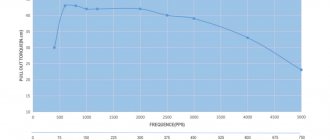
If you need to determine whether the torque of a particular motor meets the load requirements, you can compare the speed/torque characteristics of the motor with the speed/torque characteristics of the load. The torque produced by the motor must exceed the torque required by the load, including periods of acceleration and full speed.
Characteristics of the dependence of torque on the rotation speed of a standard electric motor and centrifugal pump.
As the motor approaches its rated speed, the current decreases. As would be expected, during the initial start-up period losses on the motor are high, so this period should not be long to prevent overheating.
It is very important that the maximum rotation speed is achieved as accurately as possible. This is related to power consumption: for example, a 1% increase in rotation speed over the standard maximum results in a 3% increase in power consumption.
Power consumption is proportional to the diameter of the pump impeller to the fourth power.
Reducing the diameter of the pump impeller by 10% leads to a decrease in power consumption by (1- (0.9 * 0.9 * 0.9 * 0.9)) * 100 = 34%, which is equal to 66% of the rated power. This dependence is determined solely in practice, as it depends on the type of pump, the design of the impeller and how much you reduce the diameter of the impeller.
Number of motor starts per hour
Today's sophisticated motor control systems can control the number of starts per hour for each specific pump and motor. The need to control this parameter is that every time the electric motor is started and then accelerated, a high starting current consumption is noted. The starting current heats the electric motor. If the motor does not cool down, the continuous load from the inrush current will significantly heat the motor stator windings, resulting in motor failure or shortened insulation life.
Typically, the number of starts a motor can make per hour is the responsibility of the motor supplier. For example, Grundfos specifies the maximum number of starts per hour in the technical data for the pump, since the maximum number of starts depends on the moment of inertia of the pump.