Magnet senses electric field
A. P. Pyatakov, Candidate of Physical and Mathematical Sciences
A. K. Zvezdin,
Doctor of Physical and Mathematical Sciences
“Chemistry and Life” No. 5, 2013
Wherever you look, there is a magnet. Once upon a time, schoolchildren were told only about the compass, later - about its use in industry, and recently they started talking about the future maglev train. Although one could say that any electric motor and any transformer is an electromagnet. Today, it has become easier to convince the reader of the importance of magnets: suffice it to say that he almost certainly has a magnet at home (on the refrigerator door and in the microwave), in his pocket (on his cell phone), and dozens of magnets in his computer and car. There are countless of them in industry and medicine, and elementary particle physics cannot do without them - they are located along the entire perimeter of the accelerator ring and in most elementary particle detectors.
There are permanent magnets and electromagnets. Constants have one big plus - they do not consume energy, and several disadvantages - their field cannot be adjusted (and if possible, then slowly - mechanically moving), and it cannot be very strong. Electromagnets are free from these disadvantages, but they have one that permanent magnets do not have - they consume energy, and consume a lot. Sometimes they say that the problem is solved by electromagnets with superconducting windings, like the Tokamak. But, firstly, you can’t scoop up either liquid helium or liquid nitrogen from a lake on Earth, and secondly, the magnetic field of such electromagnets is also difficult to regulate.
An idea arises: to cross electric and magnetic fields, to find a substance or create a material that, when placed in an electric field, becomes a magnet, and in a magnetic field, on the contrary, exhibits electrical properties. Such substances are described in the article by A.P. Pyatakov and A.K. Zvezdin from Moscow State University. M.V. Lomonosov and the Institute of General Physics named after. A. M. Prokhorova.
Variable permanent magnet
Magnetic and electrical phenomena have been known since ancient times, but they were connected with each other much later, after the work of the classics of electromagnetism: Oersted, Ampere, Faraday, Maxwell. Following Ampere, the magnetic properties of permanent magnets began to be explained by “molecular” currents flowing inside the substance in each molecule. Although the nature of molecular currents remained unclear for a long time, the very possibility of perpetual motion of charges inside matter seemed promising (this possibility is also realized in superconductors, but at low temperatures). If it were possible to influence molecular currents using an electric field, then it would be possible to control permanent magnets with virtually no energy loss.
From left to right
: Pierre Curie (1859–1906), Bernard Tellegen (1900–1990), L. D. Landau (1908–1968) (
right
) and E. M Lifshitz (1915–1985), I. E. Dzyaloshinsky (
left
) and D. N. Astrov, George Rado, G. A. Smolensky (1910–1986)
In 1884, French physicist Pierre Curie suggested that the existence of such molecules and substances that would be magnetized under the influence of an electric field does not contradict known laws. American electronics engineer Bernard Tellegen later proposed creating a composite - a magnetoelectric medium in the form of a suspension, where particles would float, representing magnets linked to pieces of electret. And an electret is a substance that can be “charged” with an external electric field, and after that for a long time, for example, years, it creates an electric field around itself, just like a magnet creates a magnetic field. Many good dielectrics are electrets, but materials combining the properties of both an electret and a magnet have neither been found nor created. Although they came up with a name for them - “magnetoelectrics”.
The matter got off the ground when L. D. Landau and E. M. Lifshits pointed out that magnetoelectrics should be sought among antiferromagnets, that is, crystals consisting of oppositely magnetized sublattices (Fig. 1). I. E. Dzyaloshinsky named a specific compound in 1959 - Cr2O3, and a year later the magnetoelectric effect in this material was discovered by D. N. Astrov. Several years earlier, American scientists in the group of Professor George Rado tried to discover the magnetoelectric properties of various substances, but the search was unsuccessful because they did not know about the work of Landau, Lifshitz and Dzyaloshinsky - translations of books and articles were published with a delay. Having learned about Astrov's discovery, they demonstrated the opposite effect on Cr2O3 - electric polarization induced by a magnetic field.
Rice. 1.
Antiferromagnetism.
The idea of antiferromagnetic ordering was anticipated by the drawings of Maurice Escher, for example, “Day and Night” ( a
), in neighboring nodes of a crystal cell the magnetic arrows (moments) of the ions are directed in the opposite direction (
b
)
At the same time, at the Leningrad Institute of Physics and Technology, in the group of G. A. Smolensky, they were searching for magnetic ferroelectrics. An ordinary ferroelectric is a substance that by itself, without the participation of external influences, creates an electric field both inside and outside, that is, in a sense, an electrical analogue of a permanent magnet. A magnetic ferroelectric is a material in which, in the absence of external fields, both magnetization and electric polarization would be observed. It was assumed that magnetic elements would replace ions in already known ferroelectrics, and the first “ferromagnet” (or “multiferroic”, as these materials are now called) turned out to be “complex”; it was a solid solution of (1–x)Pb(Fe2/3W1/3)O3 — xPb(Mg1/2W1/2)O3.
Ferromagnets and multiferroics: chimera terms
To my misfortune, I called upon the Spirits. I. V. Goethe, “The Sorcerer’s Apprentice”
Three classes of ferroics: ferroelectric, magnetic and ferroelastic substances. At the intersection of these sets lie multiferroicsMany common words are similar to the mythological chimera - an animal with the head of a lion, the body of a goat and the tail of a snake. So the word “bus” came from combining parts of the words “car” and “omnibus” (from the Latin omnibus
- everyone, for everyone).
In a similar way, the term “ferromagnet” is made up of two words “ferroelectric” and “ferromagnet”. The word “ferroelectric” comes from the first substance discovered in which polarization exists in the absence of an electric field (spontaneous electric polarization), Rochelle salt, named after the French pharmacist Seignette
. And there is another miracle - substances in which, when the temperature decreases, the crystal, while remaining intact, is divided into domains - areas with different orientations of the crystal lattice (this is called a structural phase transition). Thus, the word “ferromagnet” is already a rather strange hybrid, but the term “multiferroic” is even more “chimerical”.Chimera of ancient mythology
In the English-language scientific literature, the names of all these three classes of substances begin with the prefix “ferro”: ferromagnetics
,
ferroelastics
,
ferroelectrics
, although iron has nothing to do with it.
This did not prevent, however, the Japanese scientist Keichiro Aizu from calling all three classes with the general term “ ferroics
” in the middle of the last century.
A similar story happened in the English language: a piece of “omnibus” migrated to “bus”, and then bus
became an independent word, meaning in addition to bus, also a data transmission channel.In the case of ferroics, the story continued: in the early nineties of the last century, a new genie was released from the bottle - the term “multiferroic” (from the Latin multi
- many) - to denote a substance that simultaneously belongs to at least two classes of ferroics. At the beginning of our century, when new media with magnetic and electrical properties appeared, this word unexpectedly quickly gained recognition and supplanted “ferromagnet”, so that the creator of the neologism, the Swiss scientist Hans Schmid, when it comes to the term he coined, recalls Goethe’s poem, an excerpt from which is given as an epigraph.
Stir or layer?
Later, simpler compounds were found, and bismuth ferrite BiFeO3 turned out to be especially interesting (Fig. 2). Most of its remarkable properties are a consequence of its differences from the ideal cubic structure. The rotation of oxygen octahedra (Fig. 2a) leads to the fact that in this antiferromagnet the magnetic arrows of neighboring ions are no longer strictly opposite, forming an angle of less than 180 degrees. As a result, they do not completely compensate each other, and a general magnetization of the crystal appears (such materials are called weak ferromagnets). Electrical and magnetoelectric properties are due to the displacement of ions along the main diagonal of the cube, as well as distortions of the octahedron (Fig. 2b). A bismuth ferrite crystal is also capable of stretching in rays of light (Fig. 2c) and turning into a semiconductor diode under the influence of an electric field (Fig. 2d). The last transformation occurs due to oxygen vacancies - charged defects that change the type of conductivity.
Rice. 2.
Crystal structure of bismuth ferrite:
in the centers of the cubes
there are iron ions,
in the vertices
- bismuth ions,
in the centers of the faces
- oxygen ions: rotation of oxygen octahedra (
a
), displacement of ions along the diagonal of the cube and the resulting distortion of the octahedra - ion displacements are shown
by arrows
(
b
) , electrostriction in bismuth ferrite is the stretching of a sample under the influence of light radiation, under a hundred-watt lamp the relative elongation is about a thousandth of a percent, which is not so small for a solid (c
)
, the formation of a pn junction under the influence of an electric field as a result of the movement of oxygen vacancies (
g
)
There are very few such “high-temperature” magnetoelectrics as bismuth ferrite, hardly more than a dozen, and even those have a significant drawback - noticeable conductivity at room temperature. This negates the main advantage of the magnetoelectric method of producing a magnetic field - when an electric field is applied, a current will begin to flow in such a substance, which means that energy consumption becomes noticeable. Therefore, in the 70s of the last century, the first attempts were made to create artificial composite magnetoelectric media in the form of a mixture of two powders (Fig. 3a): magnetostrictive particles changed shape in a magnetic field, they influenced the piezoelectric particles, and they, in turn, the deformations became electrically polarized.
The idea was great, but the effect turned out to be small and unstable. When stirring, lumps and clots were obtained, and the formation of channels from conducting magnetostrictive particles led to a “short circuit” of the sample, and therefore to the absence of electrical voltage. Then the idea of a “layer cake” or a sandwich of magnetostrictive and piezoelectric materials glued together arose (Fig. 3b). Conducting channels were no longer formed, and the magnetoelectric effect became 50 times greater than in Cr2O3. Using sensors on sandwich structures, it was possible to measure magnetic fields a million times weaker than the Earth’s field—the kind our heart creates as it pumps blood through its vessels.
When structure affects properties
A new stage in the creation of composite materials has come with the advent of modern technologies: now artificial magnetoelectrics are produced on chips in the form of films with columnar nanostructures (Fig. 3c). Nanofilm sandwich structures do not work well - adhesion to the chip substrate does not allow them to deform freely, and the columns are easily compressed and stretched in the vertical direction. In addition, such structures did not need to be specially created; they “self-organize” when two substances are simultaneously deposited onto the substrate: magnetostrictive, for example spinel CoFe2O4, and piezoelectric, for example barium titanate BaTiO3 or bismuth ferrite BiFeO3. By changing the crystallographic orientation of the substrate, it is possible to grow both magnetostrictive pillars in a piezoelectric matrix and piezoelectric pillars in a magnetostrictive matrix (Fig. 4).
Rice. 4.
The structure of the nanocomposite depends on the crystallographic orientation of the substrate plane: substrate with (001) orientation (
a
), substrate with (111) orientation (
b
); cubes correspond to piezoelectric crystals, octahedra - crystals of magnetostrictive material
What causes the two phases to precipitate in this way? The same phenomenon that causes a drop of water to spread on clean glass and roll into a ball on a waxed surface is surface tension. If the substrate is cut perpendicular to the [001] crystallographic direction (i.e., the z
coordinate system), then the substance of the magnetostrictive material does not wet the surface, collecting into drops, which then grow into columns, while the piezoelectric phase wets the substrate and envelops the columns, forming a matrix. On the (111) substrate, everything happens the other way around: a columnar structure of a piezoelectric material grows inside the magnetostrictive matrix.
When the characteristic dimensions of nanostructures are several interatomic distances, the phases of the composite begin to influence the internal structure and properties of each other. If layers of barium titanate are interspersed with a magnetic material with a similar crystal structure, for example, lanthanum manganite with calcium substitution La0.7Ca0.3MnO3, then an artificial magnetoelectric medium is obtained: due to the close proximity, the crystal structures of the two materials are subject to mutual distortions, which leads to the interaction of the electrical and magnetic subsystems. That is, it was possible not only to create a nanostructured material, but also to carry out engineering at the atomic level, changing the very properties of the component substances.
What about Curie's original idea of magnetoelectric molecules? It can be realized in organic molecular Dy3 nanoclusters, in which the magnetic atoms are three dysprosium atoms forming a regular triangle (Fig. 5a). In the state of the molecule with the lowest energy (ground state), the magnetic arrows (moments) of dysprosium ions are oriented parallel to the opposite side of the triangle (Fig. 5a). If there were more magnetic ions (as, for example, in the recently synthesized Dy6 cluster), they would form a “carousel” of magnetic moments (Fig. 5b). This arrangement is called “toroidal” because a circular electromagnet can be created by winding a wire around a donut-shaped (torus) magnetic core. Structures with toroidal ordering, following the tradition of denoting any ordering with the word “ferro,” are called “ferrotoroids.” They have a magnetoelectric effect - the application of a magnetic field causes a redistribution of magnetic moments: the number of ions whose magnetic moments are directed along the magnetic field increases. The displacement of magnetic ions entails a redistribution of charges, so that electrical polarization occurs. However, states of the molecule in which the magnetic moments are directed clockwise and states with the moments directed counterclockwise are equally likely to occur, and in these cases the magnetoelectric effect will be opposite. So the problem remains of how to obtain toroidal structures with one direction of rotation of the magnetic moments.
Rice. 5.
Organic molecular nanocluster based on rare earth ions: mutual orientation of the magnetic moments of dysprosium cations (
a
);
with toroidal ordering of magnetic moments in an external magnetic field H, in addition to magnetization, electric polarization P ( b
) is induced;
for comparison - a toroidal electromagnet ( in the center
)
The monitor will not produce memory
Tellegen's idea of a composite consisting of magnetoelectric particles that rotate in a liquid was realized with the advent of the first model of electronic ink - the gyricon (from the Greek "rotating image"). Girikon is a polymer medium in which two-color spherical polyethylene particles are embedded, rotating inside cavities with liquid (Fig. 6). The hemispheres of the particle differed not only in color, but also in electrical charge. Therefore, they could be oriented by applying an electric field, and black letters appeared on a white background. When magnetic impurities were introduced into the particles, the electric field began to control the magnetization of the system. However, the rotation took about a second, so the idea arose to “magnetize” not electronic paper, but the main component of another type of display - liquid crystals.
Rice. 6.
Girikon: polymer with embedded black and white spherical particles (
a
), magnetoelectric composite based on girikon: dipole particles rotate in microcavities with liquid.
+/– electric, S, N — magnetic poles ( b
)
In nematic liquid crystals (from the Greek “thread”), elongated molecules are located along one direction (Fig. 7a). Liquid crystal monitors work due to the property of nematic molecules to be oriented along the field (Fig. 7b), but if magnetic nanopillars are added to the liquid crystal, they will rotate along with the molecules. The result was a magnetic material controlled by an electric field, and it responded to changes in the electric field much faster - the switching frequency was kilohertz.
Rice. 7.
Liquid crystal with magnetic nanopillars: in the absence of electrical voltage (a), when the voltage is turned on (b)
This is already faster, but the gyrikon and liquid crystal cell cannot compete with the elements of semiconductor microcircuits either in size or speed, which means they are not suitable for magnetic memory devices. Instead of liquid crystal in magnetic memory devices, it was proposed to place a layer of solid-state magnetoelectric between the electrodes, however, due to the scarcity of high-temperature magnetoelectrics and high leakage currents, magnetoelectric memory is still far from being realized.
"Smart dust" collects energy
Miniaturization of electronic devices is the path to creating wireless sensor networks consisting of many sensors capable of collecting, processing information and exchanging it with each other. Such structures are sometimes called “smart dust”. The most obvious areas of application are environmental and medical monitoring, security systems. But sensors need power, and there are problems with it: if the sensor is located inside an object (for example, in a rotating part or in the human body), then you cannot connect a wire to it, the batteries are not small enough and durable enough, and solar panels are useless in the dark.
Rice. 8.
Remote power supply of sensors: a magnetoelectric transducer based on piezoelectric and magnetostrictive materials located on a substrate made of a tapering metal plate - a waveguide acoustic concentrator (
a
), a wireless sensor network node with magnetoelectric power (
b
)
Energy harvesting seems to be an interesting alternative.
- obtaining energy from the environment. These can be systems that accumulate the energy of mechanical, temperature fluctuations or radio waves, but the energy flow coming from natural sources is small - less than 1 μW/cm2. However, it is possible to create a radiation source that creates an alternating magnetic field at the location of the sensors. The energy of a magnetic field can be converted into electrostatic energy of charged capacitors using a magnetoelectric element, which consists of layers of magnetostrictive and piezoelectric materials located on a common metal substrate in the form of a plate tapering towards one end (Fig. 8). An alternating magnetic field causes periodic deformation of the magnetostrictive plate at the resonant frequency. These mechanical vibrations are transmitted to the substrate and propagate along it, so that when approaching the narrow end, the concentration of acoustic energy and the amplitude of the vibrations increase. The vibrations of the substrate are transmitted to the piezoelectric plates, and an alternating electrical voltage arises in them. This design is a type of magnetoelectric composite material, but with the help of an acoustic concentrator it is possible to achieve a gain of two times compared to a traditional multilayer structure of bonded magnetic and piezoelectric layers.
Rice. 9.
Mechanical vibrations of a cantilever made of piezoelectric material: converted into electrical energy (
a
), piezoelectric element for collecting energy when walking (
b
)
To power implants in medicine, autonomous sensors, as well as communications and mobile electronics, it is better to use mechanical movement or vibrations, for example, vibrations of an elastic plate (in modern micromechanics and nanotechnologies such plates are called cantilevers) made of piezoelectric material (Fig. 9a). When a cantilever made of a magnetoelectric composite material oscillates in the Earth's magnetic field, the magnetostrictive layer experiences additional deformations that are transferred to the piezoelectric layer, and as a result, the amplitude of the alternating voltage reaches tens of volts. Such a device is proposed to be used on underwater vehicles and buoys, where there are always ocean waves and the Earth’s magnetic field.
One more remark must be made here: the oscillation frequencies found in natural conditions are low - hertz, tens of hertz at most. This means, on the one hand, the low power generated by the unit (power is proportional to the cube of the frequency), on the other hand, the not at all microscopic dimensions of devices capable of vibrating at these low frequencies. As a result, chargers provide only microwatts per cubic centimeter. Better results are expected from the use of other types of oscillatory motion: the human body when walking (piezoelectric elements located in the shoe (Fig. 9b) already allow one to obtain up to 1 mW/cm3) and even higher-frequency vibrations of a car engine - up to 30 mW/cm3. But in any case, we are not talking about replacing batteries in cell phones yet. The harvesting of free energy itself (“ energy harvesting”
") is reminiscent of the well-known process of “scraping the bottom of the barrel, placing it in the barns,” and this explains why in such cases another term is often used: “
energy scavenging
” (
scavenging
- cleaning, waste disposal).
The problem of the relationship between magnetic and electrical phenomena in a solid is extremely multifaceted, and this article shows only some of its aspects. This area of science is now actively developing, much remains unclear, and unknown effects await their discoverers.
Literature:
1. Smolensky G.A., Chupis I.E. Ferromagnets. "Advances in Physical Sciences", 1982, 137, 415–448. 2. Eerenstein W., Mathur ND, Scott JF Multiferroic and magnetoelectric materials. Nature, 2006, 442, 7104, 759–765, doi:10.1038/nature05023. 3. Pyatakov A.P., Zvezdin A.K. Magnetoelectric materials and multi-ferroics. "Advances in Physical Sciences", 2012, 182, 593–620.
comparison table
The main features and differences of the concepts under consideration are shown in the table:
| Criterion | Electric field | A magnetic field |
| Field Source | Electric charge. | Magnet, current. |
| Field detection | When charged particles interact. | When magnets and conductors interact with current. |
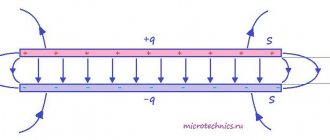
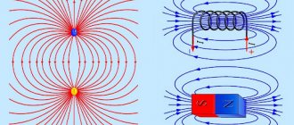
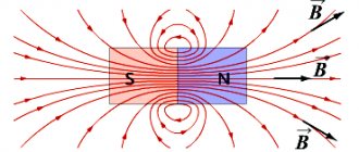
| Graphic image | Lines of force or lines of tension. | Lines of force or lines of magnetic induction. |
| Character of lines | They have a beginning and an end. The beginning of the lines of force is on positive charges, and the end is on negative charges. | They are closed. The lines leave the north pole and enter the south pole. They are closed in the magnet. |
| Interaction of elements | Charged particles of the same name attract, charged particles of the same name repel. | Opposite magnetic poles attract, like magnetic poles repel. |
| Power characteristic | The tension vector is measured in newtons per coulomb. | Magnetic induction vector, unit of measurement is tesla. |
| Field indicators | Small pieces of paper Electric Sultan Electric sleeve. | Metal filings Magnetic needle Closed circuit with current. |
| Superposition principle | The field strength at a certain point is equal to the vector sum of the field strengths that are created by each of the charges separately. | The magnetic induction of the resulting field is the vector sum of the induction of fields that are created by each source separately. |
Magnetic needle
a magnetic needle is used to study the magnetic effect of current (Figure 2).
Figure 2. Magnetic needle
- It has two poles : north (denoted by the letter $N$, colored blue) and south (denoted by the letter $S$, colored red)
- It also has an axis - a line connecting the poles
Such an arrow is the main part of any compass.
During experiments, a magnetic needle is usually placed on a point (the end of a needle or pin). This way it can rotate freely in the horizontal plane (Figure 3).
Figure 3. Using a magnetic needle