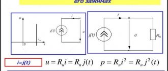
Starting his journey in electrical engineering, a student or radio electronics enthusiast soon encounters such a unit of measurement as the farad. He must know what is measured in farads, what submultiple and multiple units exist, and which of them are most often used in capacitor elements. In addition, you need to have the appropriate table and know how many microfarads per 1 kilowatt of the engine must be consumed to bring it into working condition.
Samples of different types of capacitor devices
The concept of capacity, measurement rules
This value shows how many electrons (or other charged particles) must move from one object to another to obtain the required voltage value. The latter occurs because when particles move between objects, a potential difference is formed.
The unit of measurement of the capacitive value is the farad (in writing it is indicated by the capital Cyrillic letter F). When transferring a charge of 1 Coulomb, the voltage changes by 1 Volt, the value of the capacitance between the transferred objects is 1 Farad. The formula for the dependence of capacitance on voltage is as follows:
C (capacitance) = Q (charge)/U (voltage).
If a master is going to measure the capacitance of a capacitor used in an electronic circuit, he will need a device such as a multimeter. Even a budget device can cope with the task, and the greatest accuracy is demonstrated when working with film capacitor elements. For the most accurate measurements, you can use an immittance meter, but this device has a very high price (about 120 thousand rubles). When using a multimeter, you must adhere to the following algorithm:
- Disconnect the electrical circuit from the load source. Check the lack of power by setting the device to voltage measurement mode and placing the probes to the source: the indicator should be zero.
- Remove the charge from the capacitor passively (wait 20-30 minutes) or actively (using a resistor). For small elements you need a device with a resistance of more than 2 kOhm. It is better not to work with fairly large capacitors (for example, in cameras and household appliances) at home without preparation - they accumulate a dangerously high charge. To discharge such an element, a 20 kOhm and 5 W resistor is required, connected through an insulated wire with a diameter of 3.3 mm2, designed for operation at voltages up to 600 V.
- Disconnect the capacitor from the circuit. After this, put the multimeter in capacitance measurement mode. If the device is equipped with several adjustment ranges, you need to set the one that is most likely to be correct (you can navigate by the markings). If there is a Rel key, you need to press it so that the container comes off the probe elements.
- The probes are placed at the terminals of the capacitor. When testing polarized elements, it is imperative to observe polarity. Now you need to wait for the data to be displayed on the display. If the word overload (or OL) is displayed, the indicator is too high for detection by this device or in this range (in the second case, you need to select a different range).
Important! Do not connect the multimeter to a capacitor element whose body has punctures or bulging spots. Such elements should not be used at all - they can explode when power is connected.
The process of measuring capacitance of a capacitor with a multimeter
Fundamentals of high current electrical engineering. Electrical and magnetic phenomena, page 4
As the size of a body increases, its electrical capacity also increases. \
If the body has the shape of a ball, then it turns out that one hundred electric capacity depends only on the radius: how many times the radius of one ball is greater than the radius of the second ball, the same number of times the first ball is greater than the capacity of the second ball.
That Snairmer, a sphere with a radius of 0.5 m, has an electrical capacity of 50 cm, since the radius of the sphere is 50 cm.
It should be noted that “the centimeter of capacity is an absolute unit of capacity.
There are also other practical units for measuring electrical capacitance: - 1 microfarad ==|W 000 cm.
1 farad = 1,000,000 microfarads.
Farad represents a very large unit, which is clear that
The capacity of the globe is only 707 microfarads, t.v.. 0.000707 farads.1
A sphere with a capacity of 1 farad would have a radius of 9 million kilometers.
Just as the capacity of any vessel indicates the amount of liquid that can be poured into this vessel, the electrical capacity of a body indicates its ability to perceive an electric charge, that is, the amount of electricity that can be present on the surface of a given body.
However, the amount of liquid poured into the vessel also depends on the level to which the liquid is poured. Similarly, the amount of electricity present on a charged body depends on the electrical level, i.e., on the electrical potential (voltage) of the body.
The greater the electrical capacity of a body and the higher the voltage (potential) of the charge, the greater will be the amount of electricity on this body.
Bely designated by letters: a -
amount of electricity (electric charge),
C
is the electrical capacity of the body, ,
V
is the electric potential (voltage), then we can write the following Formula:
In this formula q
must be expressed in coulombs, capacitance
C
in farads, and voltage
V
in volts.2
Now it becomes clear why such a large unit as the farad was accepted as a unit, since the ratio of the number of volts to the number of coulombs is equal to the number of farads:
However, in practical life they use not farads, but rather convenient units for use - microfarads.
Example 2. There is a ball with a radius of 1.5 m, charged to electric potential. 10000 volts. Determine the amount of electricity on this ball.
,See example 3 on the next page.
Keep in the formula connecting the amount of electricity d
with capacitance
C
and voltage
V,
express the amount of electricity in absolute units, and capacitance
C
in centimeters, then we should not forget that in this case the voltage
tion _
must be expressed in absolute units.
ELECTRICAL INDUCTION
Solution. The capacity of the ball is equal to the number of centimeters * radius and therefore
Amount of electricity:
Example3.
Find the capacity of the globe.
Solution. It is known that 1 meter is equal to one ten-millionth of a quarter of the meridian. Therefore, 1 m is 40 million times less than the circumference of the globe (meridian); it follows that the circumference of the globe is 40 million meters:
whence the radius of the globe is equal to:
The capacity of the globe is equal to the number of centimeters of its radius, and therefore: or
§ 10. Electrical induction.
Let's perform an interesting experiment: take ball A
and electrify it, say, with positive electricity (Fig. 24)'.
Let us take another ball B,
which was not charged before the experiment;
It turns out that ball B,
being
at some distance
A B,
facing the charged ball, negative electricity is obtained or, as they say, induced, and on the opposite side, positive electricity.
In this case, ball A,
exciting, or inducing, electricity on ball
B,
does not itself lose any of its own charge.
Consequently, the electricity on ball B
arose under the influence of ball
A;
This phenomenon is called
electrical induction,
or
electrification"* through influence. \;
.
So, the phenomenon of electrical induction is that, under the influence of a charged body, both types of electricity are simultaneously induced on another conductive body close to it: electricity opposite to the charged body is attracted to the side closest to the charged body, and electricity of the same name is repelled by the charged body in the opposite side.
If you remove ball B
from ball
A,
then the positive electricity • on ball
B
will again connect with the negative;
they will destroy each other, and
no electrical charge will be detected on ball
B.
A different picture will turn out if we bring ball B
to the charged ball
A,
touch it with your hand or even connect it to the ground (Fig. 25).
In this case, only part of the electricity on body B
will go into the ground;
this electricity is called free electricity.
The other part, called
bound electricity,
cannot go into the ground, since it will be attracted by the charge of body
A.
Let us now destroy the connection with the ground and remove ball
B
from ball
A;
then ball
B
will remain electrified with negative electricity, since there is nothing for it to connect with.
A completely similar picture would result if ball A
was charged with negative electricity;
in this case, two types of electricity would also appear on the surface of ball B
: bound - positive and free - negative electricity.:
When
ball
B
to the ground, free negative electricity will go into the ground, and bound positive electricity will remain on the surface of ball
B.
The phenomenon of electrical induction It is possible to explain the reason for the attraction of various light objects by electrified bodies. Indeed, let us take a glass rod electrified with positive electricity (Fig. 26) and bring it closer to balls made from punched holes. Under the influence of electrical induction, two types of electricity will arise in each ball: negative and positive. The negative charge will be attracted to the stick, and
the positive one will be repelled from it, but the attraction will be stronger than the repulsion, since the negative charge is located closer to the electrified rod than the positive one.
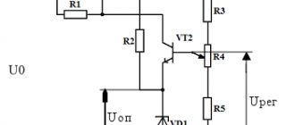
Capacitor, device with standardized capacity
Current work - how is it measured?
This device is specially designed to change the voltage indicator in accordance with the accumulated charge. Different objects can have capacitor properties, but the main difference between a device is the presence of a fixed capacitance. When a charge of 1 Coulomb appears between the plates of an element with a capacity of 1 F, a voltage of 1 V arises between them.
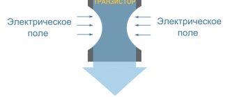
Important! Novice circuit designers often make mistakes based on ignoring the impossibility of instantly changing the voltage on a device. If a transistor connected to a capacitor opens as quickly as possible, it will overheat or even burn out. When the terminals of a charged device are shorted, the current will be very high, but still not infinite. It is limited by the resistance of the element and its output parts.
The devices are used not only in radio electronics, but also, for example, when working with engines. When using a starting capacitor and an additional winding for 1 kW of power, 70 microfarads of capacitance will be required. Knowing this, you can calculate the total amount of capacity required.
Capacity Usage
Capacitors are devices for storing charge in electronic equipment
Symbols of capacitors on circuit diagrams
The concept of electrical capacitance refers not only to a conductor, but also to a capacitor. A capacitor is a system of two conductors separated by a dielectric or vacuum. In its simplest form, the capacitor design consists of two electrodes in the form of plates (plates). A capacitor (from Latin condensare - “to compact”, “to thicken”) is a two-electrode device for storing charge and energy of an electromagnetic field; in the simplest case, it consists of two conductors separated by some kind of insulator. For example, sometimes radio amateurs, in the absence of ready-made parts, make tuning capacitors for their circuits from pieces of wire of different diameters, insulated with a varnish coating, with a thinner wire wound around a thicker one. By adjusting the number of turns, radio amateurs precisely tune the equipment circuit to the desired frequency. Examples of images of capacitors on electrical circuits are shown in the figure.
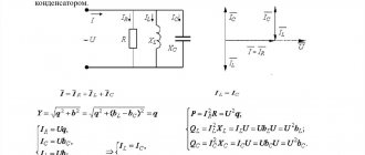
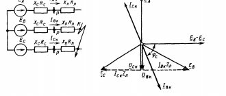
Parallel RLC circuit consisting of a resistor, capacitor and inductor
Historical reference
Even 275 years ago, the principles of creating capacitors were known. Thus, in 1745 in Leiden, the German physicist Ewald Jürgen von Kleist and the Dutch physicist Pieter van Muschenbrouck created the first capacitor - the “Leyden jar” - in which the dielectric was the walls of a glass jar, and the plates were the water in the vessel and the experimenter’s palm holding the vessel. Such a “can” made it possible to accumulate a charge on the order of a microcoulomb (µC). After it was invented, it was often experimented with and performed in public. To do this, the jar was first charged with static electricity by rubbing it. After this, one of the participants touched the can with his hand and received a small electric shock. It is known that 700 Parisian monks held hands and conducted the Leiden experiment. The moment the first monk touched the head of the jar, all 700 monks, overcome by one convulsion, screamed in horror.
The “Leyden jar” came to Russia thanks to the Russian Tsar Peter I, who met Muschenbruck while traveling in Europe, and learned more about the experiments with the “Leyden jar”. Peter I established the Academy of Sciences in Russia, and ordered Muschenbruck various instruments for the Academy of Sciences.
Subsequently, capacitors were improved and became smaller, and their capacity became larger. Capacitors are widely used in electronics. For example, a capacitor and inductor form an oscillating circuit that can be used to tune a receiver to the desired frequency.
There are several types of capacitors, differing in constant or variable capacitance and dielectric material.
Examples of capacitors
Oxide capacitors in the server power supply.
The industry produces a large number of types of capacitors for various purposes, but their main characteristics are capacity and operating voltage.
Typical capacity
capacitors vary from units of picofarads to hundreds of microfarads, with the exception of ionistors, which have a slightly different nature of capacitance formation - due to the double layer of the electrodes - in this they are similar to electrochemical batteries. Nanotube-based supercapacitors have extremely developed electrode surfaces. These types of capacitors have typical capacitance values in the tens of farads, and in some cases they can replace traditional electrochemical batteries as current sources.
The second most important parameter of capacitors is its operating voltage
. Exceeding this parameter can lead to failure of the capacitor, therefore, when constructing real circuits, it is customary to use capacitors with double the operating voltage.
To increase the capacitance values or operating voltage, the technique of combining capacitors into batteries is used. When two capacitors of the same type are connected in series, the operating voltage doubles and the total capacitance is halved. When two capacitors of the same type are connected in parallel, the operating voltage remains the same, but the total capacitance doubles.
The third most important parameter of capacitors is the temperature coefficient of change in capacitance (TKE)
. It gives an idea of the change in capacity under changing temperatures.
Depending on the purpose of use, capacitors are divided into general-purpose capacitors, the requirements for the parameters of which are not critical, and into special-purpose capacitors (high-voltage, precision and with various TKE).
Capacitor markings
Like resistors, depending on the dimensions of the product, full markings may be used indicating the rated capacity, class of deviation from the rated value and operating voltage. For small-sized versions of capacitors, code markings of three or four digits, mixed alphanumeric markings and color markings are used.
The corresponding tables for converting markings by rating, operating voltage and TKE can be found on the Internet, but the most effective and practical method of checking the rating and serviceability of an element of a real circuit remains the direct measurement of the parameters of a soldered capacitor using a multimeter.
The oxide capacitor is assembled from two aluminum strips and a paper gasket with electrolyte. One of the aluminum strips is coated with a layer of aluminum oxide and serves as the anode. The cathode is a second aluminum tape and a paper tape with electrolyte. The aluminum strips show traces of electrochemical etching, which allows them to increase their surface area, and therefore the capacitance of the capacitor.
Warning:
Since capacitors can accumulate a large charge at very high voltages, to avoid electric shock, it is necessary to discharge the capacitor before measuring its parameters by shorting its terminals with a wire with high external insulation resistance. The standard meter leads are best suited for this.
Oxide capacitors:
This type of capacitor has a large specific capacitance, that is, capacitance per unit weight of the capacitor. One plate of such capacitors is usually an aluminum strip coated with a layer of aluminum oxide. The second plate is the electrolyte. Since oxide capacitors have polarity, it is fundamentally important to include such a capacitor in the circuit strictly in accordance with the polarity of the voltage.
Solid capacitors:
Instead of a traditional electrolyte, they use an organic polymer that conducts current, or a semiconductor, as the plating.
Three-section variable air condenser
Variable capacitors:
Capacitance can be changed mechanically, electrically, or by temperature.
Film capacitors:
The capacitance range of this type of capacitor is approximately 5 pF to 100 µF.
There are other types of capacitors.
Ionistors
These days, ionistors are gaining popularity. An ionistor (supercapacitor) is a hybrid of a capacitor and a chemical current source, the charge of which accumulates at the interface between two media - the electrode and the electrolyte. The creation of ionistors began in 1957, when a capacitor with a double electrical layer on porous carbon electrodes was patented. The double layer, as well as the porous material, helped increase the capacitance of such a capacitor by increasing the surface area. Subsequently, this technology was supplemented and improved. Ionistors entered the market in the early eighties of the last century.
With the advent of ionistors, it became possible to use them in electrical circuits as voltage sources. Such supercapacitors have a long service life, low weight, and high charging and discharging rates. In the future, this type of capacitors can replace conventional batteries. The main disadvantages of ionistors are lower specific energy (energy per unit weight) than electrochemical batteries, low operating voltage and significant self-discharge.
Ionistors are used in Formula 1 cars. In energy recovery systems, braking generates electricity, which is stored in the flywheel, batteries or ionistors for later use.
University of Toronto A2B electric car. General form
In consumer electronics, ionistors are used to stabilize the main power supply and as a backup power source for devices such as players, flashlights, automatic utility meters and other battery-powered devices with variable loads, providing power at increased loads.
In public transport, the use of ionistors is especially promising for trolleybuses, since it becomes possible to implement autonomous operation and increase maneuverability; ionistors are also used in some buses and electric vehicles.
University of Toronto A2B electric car. Under the hood
Electric cars are currently produced by many companies, for example: General Motors, Nissan, Tesla Motors, Toronto Electric. The University of Toronto has teamed up with Toronto Electric to develop the all-Canadian A2B electric vehicle. It uses supercapacitors together with chemical power supplies, so-called hybrid electric energy storage. The engines of this car are powered by batteries weighing 380 kilograms. Solar panels installed on the roof of the electric vehicle are also used for recharging.
Capacitive touch screens
Modern devices increasingly use touch screens, which allow you to control devices by touching indicator panels or screens. Touch screens come in different types: resistive, capacitive and others. They can respond to one or more simultaneous touches. The operating principle of capacitive screens is based on the fact that a large capacitance object conducts alternating current. In this case, this object is the human body.
Surface capacitive screens
The iPhone touch screen is made using projected capacitive technology.
Thus, a surface capacitive touch screen is a glass panel coated with a transparent resistive material. An alloy of indium oxide and tin oxide, which has high transparency and low surface resistance, is usually used as a resistive material. Electrodes that supply a small alternating voltage to the conductive layer are located at the corners of the screen. When you touch such a screen with your finger, a current leak appears, which is detected in the four corners by sensors and transmitted to the controller, which determines the coordinates of the touch point.
The advantage of such screens is their durability (about 6.5 years of clicks with an interval of one second or about 200 million clicks). They have high transparency (approximately 90%). Thanks to these advantages, capacitive screens have been actively replacing resistive screens since 2009.
The disadvantage of capacitive screens is that they do not work well at low temperatures; there are difficulties in using such screens with gloves. If the conductive coating is located on the outer surface, then the screen is quite vulnerable, so capacitive screens are used only in those devices that are protected from the elements.
Projected capacitive screens
In addition to surface capacitive screens, there are projection capacitive screens. Their difference is that a grid of electrodes is applied on the inside of the screen. The electrode that is touched forms a capacitor together with the human body. Thanks to the grid, you can get precise touch coordinates. The projected capacitive screen responds to touches when wearing thin gloves.
Projected capacitive screens also have high transparency (about 90%). They are durable and quite strong, so they are widely used not only in personal electronics, but also in automatic machines, including those installed on the street.
Author of the article: Sergey Akishkin, Tatiana Kondratieva
Application area
Capacitor Capacitance: Unit of Measurement
This unit of measurement is used not only for the capacitance of capacitors, but also for other conductive elements (for example, wires). Since 1 farad is a fairly significant capacitance, small industrial capacitor elements often have values of hundredths, thousandths, etc. fractions of a farad, for example, microfarads are designated microfarads. For ionistor ultra-high-capacity elements, on the contrary, the indicator can be measured in kilofarads.
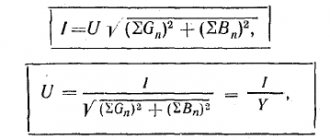
Application of Farad:
Farads measure the electrical capacitance of conductors, cables, interelectrode capacitances of various devices and capacitors, that is, their ability to accumulate electrical charge.
There is a distinction between electrical capacitance and electrochemical capacitance. Electrochemical capacitance applies to conventional batteries and accumulators. It has a different nature and is measured in other units: ampere-hours, commensurate with the electric charge (1 ampere-hour is equal to 3600 coulombs).
Multiples and submultiples
Most often in electronics, elements with small capacitances are used, which is why those starting to work with circuits have questions: pF is how many farads, 100 nf is how many microfarads, and so on. In this regard, you should have with you a table of conversion of one unit to another. The most commonly used submultiple units include:
- microfarad (μF) – 0.000001 F;
- nanofarad (nF) – 0.000000001 F;
- picofarad (pF) – 0.000000000001 F.
Of the multiple units, the kilofarad (kF) is used, equal to a thousand farads. Such indicators are typical for ionistors. For conventional capacitors, the capacitance is usually measured in a maximum of tens of farads.
In the Soviet Union, there was a tendency on electrical circuits and capacitor housings to indicate the capacitance value as a whole number (for example, 35). To mean picofarads, and a fraction with one digit after the decimal point meant microfarads. Letters were not used in such container markings. On modern domestic capacitors, when indicating the capacitance in picofarads, the measuring units are usually not written after the number. If the letters “mk” are indicated, microfarads are implied, if “n” - nanofarads are implied. Abroad they use markings made of colored stripes.
Table for converting some fractional capacitance units to others
Notes[edit]
- ^ a b International System of Units (SI) (8th ed.). Bureau International des Poids et Mesures (International Committee of Weights and Measures). 2006. p. 144.
- Peter M. B. Walker, ed. (1995). Dictionary of Science and Technology
. Larousse. ISBN 0752300105. - Bright and Clark suggested "ohm" for voltage, "farad" for charge, "galvate" for current, and "volt" for resistance as names for various electrical quantities. See:
- Latimer Clarke and Sir Charles Bright (1861) "On the Formation of Standards for the Quantity of Electricity and Resistance", Report of the Thirty-First Meeting of the British Association for the Advancement of Science
(Manchester, England: September 1861), section: Mathematics and Physics, pp. 37–38.
Latimer Clarke and Sir Charles Bright (9 November 1861) "Measurement of Electrical Quantities and Resistance", Electrician
,
1
(1): 3–4. - Latimer Clarke and Sir Charles Bright (1861) "On the Formation of Standards for the Quantity of Electricity and Resistance", Report of the Thirty-First Meeting of the British Association for the Advancement of Science
- Sir W. Thomson et al (1873) "First Report of the Committee on the Selection and Nomenclature of Dynamic and Electrical Units", Report of the 43rd Meeting of the British Association for the Advancement of Science
(Bradford, September 1873), pp. 222-225 . From paragraph 223: "An ohm" represented by the original standard coil is approximately 10 9 CGS units of resistance: a "volt" is approximately 10 8 CGS units of electromotive force: and a "farad" is approximately 1/10 9 units of LPG power." - (Anon.) (September 24, 1881) “Electrical Congress,” The Electrician
,
7
: 297. From page 297: “7. The name farad will be given to the capacitance determined by the condition that a pendant in a farad gives a volt.” - Tunbridge, Paul (1992). Lord Kelvin: His Influence on Electrical Measurement and Units of Measurement. London: Peregrine. pp. 26, 39–40. ISBN 9780863412370. Retrieved May 5, 2015.
- Braga, Newton S. (2002). Robotics, mechatronics and artificial intelligence. Newnes. paragraph 21. ISBN 0-7506-7389-3. Retrieved September 17, 2008. Common units of measurement are microfarads (µF), which corresponds to 0.000.001 F; nanofarad (nF), which is 0.000,000.001 F; and picofarad (pF), which is 0,000,000,000,001 F.
- Platt, Charles (2009). Brand: Electronics: Learning through Discovery. O'Reilly Media. paragraph 61. ISBN 9781449388799. Retrieved July 22, 2014. Nanofarads are also used more often in Europe than in the US.
- Gregoriansky, Roubik (1976). Analog MOS integrated circuits for signal processing
. John Wiley and Sons. paragraph 78. - ↑
Pease, Bob (2 September 1993). “Anyway, what is this femtoamp?” . Electronic design. Retrieved March 9, 2013. - ↑
Pease, Bob (December 1, 2006). “What is this best material anyway?” . Electronic design. Retrieved March 9, 2013. - Jump up ↑
Williams, L.L. (January 1999). "Electrical Properties of the Atmosphere in Fair Weather and the Possibility of Observable Discharge on Moving Objects" (PDF). Archived from the original (PDF) on December 21, 2016. Retrieved August 13, 2012. - "Puff". Wolfram Research. Retrieved June 9, 2009.
- "1940 Radio Shack Catalog - Page 54 - Capacitors". radioshackcatalogs.com
. Archived from the original on July 11, 2022. Retrieved July 11, 2022. - "Daraf". Webster's Online Dictionary. Archived from the original on 2011-10-04. Retrieved June 19, 2009.
- Graf, Rudolf F. (1999). Modern Dictionary of Electronics. Newnes. item 1. ISBN 9780080511986. Retrieved April 15, 2016.
Application of capacitors
This category of elements is very widely used in all areas of electronics and a number of other industries. Among the main areas of application are:
- television and sound reproducing equipment;
- radar devices (here capacitors help generate pulses and increase their power);
- telephone and telegraph devices - in them devices are used to separate types of circuits (by frequency, variability-constancy) and extinguish sparks in contacts;
- measuring electronic instruments;
- lasers (increasing pulse power);
- overvoltage protection in electrical power plants;
- electric welding work using a discharge;
- blocking machine-generated radio interference;
- starting electric motors and creating a phase shift in the additional winding;
- generators used during electrical testing to produce current and voltage pulses.
Capacitor element dimensions
Capacitor elements are used in a very wide range of areas - from printed circuit boards (miniature SMD components) to powerful motors and pulse generators. To correctly select a capacitor, you need to be able to decipher the markings and symbols on the diagrams, in particular, navigate the symbols of device capacitance.
Shape of the Earth
Hammer-Aitov projection
The circumference and diameter of the Earth are different because its shape is an oblate spheroid or ellipsoid instead of a true sphere. The planet's poles flatten slightly, resulting in a bulge at the equator and therefore a larger circumference and diameter.
The Earth's equatorial bulge is 42.72 km and is caused by the planet's rotation and gravity. Gravity itself causes planets and other celestial bodies to collapse and form a sphere. This is due to the fact that it pulls the entire mass of the object as close as possible to the center of gravity (the earth's core in this case).
As the planet rotates, the sphere is distorted by centrifugal force. It is the force that causes objects to move outward from their center of gravity. When the Earth rotates, the centrifugal force is greatest at the equator, so it causes a slight outward bulge, giving that area a larger circumference and diameter.
Local topography also plays a role in the shape of the Earth, but on a global scale it is minor. The greatest differences in local topography around the world are Mount Everest, the highest point above sea level at 8,848 m, and the Mariana Trench, the lowest point below sea level at 10,994 ± 40 m. This difference is only about 19 km, which is very insignificant on a planetary scale. If we consider the equatorial bulge, the highest point in the world and the place farthest from the center of the Earth is the summit of the Chimborazo volcano in Ecuador, which is the highest peak near the equator. Its height is 6,267 m.