Very often in robotics there is a need to smoothly control some process, be it the brightness of an LED, the power of a heater, or the rotation speed of a motor. It is quite obvious that the control is directly related to the change in voltage at the consumer: the LED will light differently and the motor will spin at a different speed. But the problem is that only such a thing as a DAC - a digital-to-analog converter - can control the voltage, and our microcontroller does not have a built-in DAC, we only have a digital signal, i.e. either on or off:
Is it possible to achieve smooth control of a digital signal? It turns out it is possible! Imagine a fan spinning at full power, the voltage constant. Let us now imagine that the voltage is applied for a second, and not for a second, and so it continues “in a circle”. The fan will start spinning twice as slow , but we will most likely notice moments of turning on and off, especially if the fan is small. A large fan is more inert and you may not even notice changes in speed within two seconds. You can now turn on the voltage for 0.5 seconds, and turn it off for the remaining 1.5 seconds. The fan will spin at 25% of maximum speed. We were able to present the so-called PWM signal, pulse width modulation
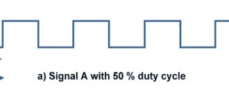
It will also work with an incandescent light bulb, because it is very inert, but with an LED we will see how it turns on and off, because it has practically no on/off delay. What to do? It's very simple, raise the frequency. In the thought experiment we had a period of 2 seconds, which is 0.5 Hz. Now imagine such a signal with a frequency of, say, 1000 Hz. Or 25'000 Hz (25 kHz). Now the inertia of the eye plays a role; it will not notice flashes at such a frequency, for it it will simply be a decrease in brightness. Problem solved! By changing the so-called “filling” of the PWM signal, you can change the “total” voltage (integrated) over a certain period. The higher the PWM fill, the higher the voltage, but not higher than the voltage we “PWM”:
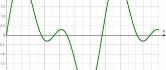
Using a PWM signal, you can even modulate complex analog signals, for example, a sine wave. The picture below shows PWM (bottom) and the same PWM after filters:
By the way, this is how DC-AC inverters work. Returning to the properties of a PWM signal, there are only two of them: frequency (frequency) and duty (duty), we have dealt with them. Let's move on to generating PWM using Arduino.
What is PWM?
PWM (pulse-width modulation, English pulse-width modulation (PWM)) is a method of controlling power by pulsed power supply. The power varies depending on the duration of the applied pulses.
PWM is used everywhere in modern electronics, to adjust the brightness of the backlight of your smartphone, the speed of rotation of the cooler in the computer, to control the motors of a quadcopter or hoverboard. The list can be continued endlessly.
In hobby electronics, PWM controllers are often used to control the brightness of LED strips and to control powerful DC motors.
The Analog Designer's Cookbook: Op-Amps 12
Tim Green, Pete Semig, Colin Wells (Texas Instruments)
Here is a chapter from the Analog Electronics Developer's Cookbook, created by engineers at Texas Instruments (TI ) . The cookbook is a collection of recipes, and this series of articles is a collection of standard circuits with operational amplifiers . A separate article is devoted to each scheme, containing an example of a typical calculation indicating formulas and sequence of actions. The calculation results are additionally checked in the SPICE modeling . Calculations were performed for specific amplifiers from the TI product line. The developer can use other products, a wide selection of which is presented on the pages of the COMPEL company catalog . The reader is required to understand the basic operating principles of op-amps. If knowledge is not enough, you should first familiarize yourself with the TI Precision Labs (TIPL) training courses . The authors promise to update and supplement the articles in the series.
We publish chapters of the Cookbook on our website regularly - twice a month.
PWM operating principle
Unlike linear systems, where power is regulated by reducing electrical parameters (current or voltage), when using PWM, the power transmitted to the consumer is regulated by the pulse time, which significantly increases the efficiency of the controller. In analog systems, the residual power was dissipated in the form of heat; here, when consumption is reduced, the residual power is simply not used.
The main characteristic of PWM is DUTY DUTY (percentage of filling) - the percentage ratio of the pulse duration to the period. The figure below shows 5 duty cycles of a rectangular PWM signal:
PWM duty cycle
PERIOD is the time during which a full cycle of signal oscillation occurs. Measured in seconds. It depends linearly on the signal frequency and is calculated by the formula:
T(period) = 1/f(frequency)
f(frequency) = 1/ T(period)
The PWM frequency is the number of periods (or, if you prefer, oscillation cycles) per unit of time. Frequency is measured in Hertz (Hz), 1 Hz is one oscillation every 1 second.
If the signal makes 100 oscillations per second, then the frequency is 100 Hz. The higher the frequency, the shorter the period.
Basic equipment
digital generators ZET 7060-G
The basic package of generators includes:
- digital generator ZET 7060-G;
- DIN rail mounting panel for plastic modules 71×39;
- set of operational documentation.
Digital generators comply with the requirements of Directive 2011/65/EU (ROHS, ROHS II) on the restriction of the use of hazardous substances (Pb, Hg, Cd, Cr(VI)) in electrical and electronic equipment and are manufactured using lead-free technology, in accordance with the requirements of the European Community
How to connect to the load
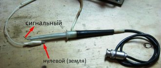
The PWM signal generator should not be connected directly to the load, because it is low-current and will most likely burn everything out immediately. In order to control the load, you need a switch on a mosfet transistor. We take an N-channel mosfet transistor IRF3205 and assemble everything according to the diagram:
Arduino PWM on IRF3205
Resistor R1 is needed to protect the Arduino pin from burnout, and resistor R2 is needed to ensure that the transistor is completely closed when the Arduino does not provide an output signal.
As you can see, nothing complicated. Four elements and the PWM controller is ready. He can already control a single-color LED strip or some kind of motor.
If you need a three-color ribbon or more ribbons (we make multi-channel PWM), simply add keys to pins D3, D5, D6, D9, D10, D11 ( only PWM works on them ). In total, Arduino is capable of controlling the power of 6 devices simultaneously.
The IRF3205 is capable of withstanding currents of up to 70 Amps at voltages of up to 55 Volts; such characteristics are quite sufficient to solve most household problems.
Controlling SG90 servo drive without microcontroller
I came across the popular inexpensive SG90 servo drive. And I decided to control it, but without a microcontroller. In this article I will outline the developer’s train of thought when implementing one of the solution options.
For anyone interested, please see cat.
You need to control the servo drive, but without a microcontroller.
Knowledge
Everyone knows that experience and knowledge help create and find solutions. On the pages of Giktayms there are many examples of using a servo drive using controllers. They tell in detail about the servo drive control system. Let's take this experience of other developers as the knowledge we need to solve the problem. The SG90 servo drive is controlled by a PWM signal, the parameters of which determine the position of the rotor. The PWM period is about 20 mS, the duration of the control signal is from 500 to 2100 μS.
Task
Idea and knowledge give rise to a problem that needs to be solved. Let's formulate a task to implement the idea. This is something like a Technical Specification. It seems that everything is simple, you need to take a pulse generator with a variable duty cycle, connect power to the servo drive, and send a control signal from the generator. We especially note that the requirements include changes in duty cycle - that is, there must be controls or a user interface.
Implementation
This is where the pangs of creativity begin: what to get and where to get it? You can find a ready-made laboratory pulse generator, for example G5-54 with knobs and buttons, set the necessary parameters, and connect the generator to a servo drive. However, this is cumbersome and not everyone has this luxury. Therefore, developers, relying on their experience and knowledge, try to combine desire (idea-task) and capabilities (material and creative) to implement the task. Material possibilities are that “toad”: “How much and what do I want to spend on implementing the idea?” Creative possibilities are, “Let me see what I already have.” These are not necessarily any material assets, but experience and knowledge of previous developments that can be adapted for implementation. It would also be a good idea to search (Google) to see if someone has already implemented something similar. To reduce solution options, you yourself need to add additional requirements that limit the imagination of implementation. For example, let’s add one more condition to the requirements, let it be a material limitation, implementation must be inexpensive
.
If you need to control the positive contact
In this case, we will need another mosfet transistor - P-channel. The circuit is similar, only the pull-up resistor is connected to the positive.
You will also need to invert the signal at the Arduino output, because when 5 volts are applied, the transistor will close, and when 0 volts is applied, it will open, which means that a PWM with a duty cycle of 30% will produce 70% power at the output of the circuit.
PWM on irf4905, power supply 5 v
It is worth making a reservation that such a circuit will only work with a power supply no higher than 5 volts , since in order to completely close the P-channel transistor it is necessary to pull its gate to the power positive, and the arduino is capable of delivering only 5 volts to the digital pin. This means that when powered at least slightly higher than the voltage supplied to the digital pin, the transistor will not completely close at the top of the PWM pulse and WILL HEAT VERY HEATED. It will also not be able to completely turn off the load.
If you need to control, for example, a 12-volt device, then the circuit will become a little more complicated. A so-called “swing arm” or field-effect transistor driver will be added. According to the classics, it is assembled on two and sometimes three transistors, but we have a slightly simpler option that works at low frequencies:
Arduino, PWM control via positive wire IRF4905
Functional signal generators for testing devices: inexpensive models from Aliexpress
Low-cost digital generators for testing devices that will not only be useful as a hobby generator for a radio amateur, but also suitable for professional testing and component development. The selection will include test signal generators for testing equipment, TVs and monitors, for motor control (PWM), as well as high-frequency generators, including for radio communications, as well as for DDS modules and RF generators for self-assembly.
For the purpose of testing and checking equipment, various types of signals of the required shape, frequency and duty cycle, amplitude, etc. are used. An example of such testing can be seen in a recent review of the Rubyster 1C15 oscilloscope with a bandwidth of up to 110 MHz. I used an inexpensive JDS-2900 generator with a generation range of up to 60 MHz.
I’ll start with, perhaps, one of the most budget-friendly options, namely the PWM (PWM) signal generator FNIRSI XY-PWM1, with a signal generation range from 1 Hz to 150 KHz. The duty cycle, duration and pulse repetition period are adjustable. There is also a timer to turn off generation. It is convenient to set up using buttons with control on the display. The device is based on the Nuvoton N76 series controller, so it’s an interesting option.
Juntek's portable function generator is model JDS2900-60M with a 60 MHz generation range. It is a compact digital two-channel DDS signal generator with a BNC output (x2). There is a built-in frequency counter. You can customize the signal for yourself or use the preset ones (sine, square wave, saw). What to check like this? Yes, at least new models of oscilloscopes and multimeters.
The simplest model for a radio amateur is a DDS functional signal generator based on a microcontroller. The device has a frequency range from 1 Hz to 65534 Hz. The signal shape can be customized: sine, square, and triangular output signals are available. The signal edges are clear. Wide range of adjustments and settings. Output: BNC connectors. Wires and adapters for such a generator can be made independently. This generator is suitable for testing and checking audio devices.
An excellent functional arbitrary waveform generator from UNI-T. There are two models to choose from in the lot: UNI-T UTG932 and UNI-T UTG962. They differ accordingly in the maximum generation frequency: 30 MHz and 60 MHz, respectively. Both models are two-channel. It has a large screen and serious functionality, including phase change. A precision digital signal source of 200 Ms/s (14 bit DAC) is installed inside. A built-in frequency meter is provided.
If you are looking for a very inexpensive, but highly stable and, at the same time, high-frequency functional signal generator, then pay attention to the ready-made CJMCU-5351 modules based on the Si5351/Si5351A generator. It is a separate module for connecting to the controller via the I2C bus; the output is set depending on the signal. The clock frequency of the microcircuit is 25 MHz, but the module contains multipliers and frequency dividers; a real signal can be obtained up to 160 MHz. Minimum - from 8 kHz. Suitable for Arduino, STM32, and other debugging boards. The module is solderable, the kit includes a standard comb with a pitch of 2.54 mm. The RF output is made with SMA-type connectors. This is the most budget option of this plan.
This is probably the most inexpensive signal generator with the ability to get sine/triangle/square output. Sold as a kit to be assembled. The kit contains an acrylic body and everything you need. The XR2206 chip makes it possible to generate a test signal within the range of 1 Hz-1 MHz. You can adjust the output amplitude within the desired limits.
A convenient and inexpensive version of a pulse signal generator module, similar to the one that was at the beginning of the collection. It is a separate module without a housing, with a built-in display and a PWM or pulse signal generator. You can set the pulse frequency, repetition period and pulse duty cycle. Operating range from 1Hz to 150Khz, output voltage limits from 3.3 V to 30 V.
Special module with test signals for VGA monitors. It is a small board with a specialized chip. Powered by 7 V to 12 V (works from any power supply or 9 V Krona battery). Convenient for testing LCD displays for repair or purchase. It produces several standard pictures for checking the matrix.
Another low-cost DDS signal generator module based on the AD9833. This time the characteristics are a little simpler, the price is lower. Also works with Arduino and STM32 microcontrollers. A convenient and inexpensive way to assemble a signal generator at home with a sine, square, or triangular output signal. The RF output is made with SMA-type connectors.
One of the best HackRF generator boards with a software receiver (SDR). It can not only receive any signal in the range from 1 MHz to 6 GHz, but also generate a signal to the antenna. Can be used for amateur radio purposes, for research, for a student or PhD project. In fact, these are the popular RTL-SDRs, but with extended range and signal transmission capabilities. There are several configuration options on the link; this is one of the most affordable lots on Aliexpress.
Using the NE555 timer. Part 2 - NE555 square wave generator
Example No. 7 - A simple square wave generator on the NE555
When the circuit is turned on, capacitor C1 is discharged and output 3 of the NE555 timer is at a high level. Then capacitor C1 begins to gradually charge through resistor R1.
At the moment when the potential on the capacitor, and accordingly at pin 6 (stop) of the timer, reaches approximately 2/3 of the supply voltage, the signal at pin 3 will switch to a low level. Now the capacitor begins to discharge through resistance R1. When the voltage level at input 2 (start) drops to 1/3 Usupply, the output will again be high. And the process will repeat again.
Voltage stabilizer on a powerful field-effect transistor 13V (IRLR2905)
When building high-current voltage stabilizers, radio amateurs usually use specialized microcircuits of the 142 series and similar ones, “amplified” by one or more bipolar transistors connected in parallel. If you use a powerful switching field-effect transistor for these purposes, you will be able to assemble a simpler high-current stabilizer,
The diagram of one of the variants of such a stabilizer is shown in Fig. 3.28.0. From the secondary winding of the transformer, an alternating voltage of about 13 V (effective value) is supplied to the rectifier and smoothing filter. On the filter capacitors it is equal to 16 V. This voltage is supplied to the drain of the powerful transistor VT1 and through resistor R1 to the gate, opening the transistor.
Part of the output voltage through the divider R2, R3 is supplied to the input of the DA1 microcircuit, closing the OOS circuit. The voltage at the output of the stabilizer increases until the voltage at the control input of the DA1 microcircuit reaches the threshold, about 2.5 V. At this moment, the microcircuit opens, lowering the voltage at the gate of the powerful transistor, i.e. partially closing it, and thus the device enters stabilization mode. The best results can be obtained if diode VD2 is connected to a rectifier bridge (Fig. 3.28.6). In this case, the voltage across capacitor C5 will increase, since the voltage drop across diode VD2 will be less than the voltage drop across the bridge diodes, especially at maximum current.
If it is necessary to smoothly adjust the output voltage, the constant resistor R2 should be replaced with a variable or adjusted resistor.
The stabilizer uses a powerful field-effect transistor IRLR2905 as a regulating element. Although it is designed to operate in switching mode, in this stabilizer it is used in linear mode. The transistor has a very low channel resistance in the open state (0.027 Ohm), provides a current of up to 30 A at a case temperature of up to 100 ° C, has a high transconductance and requires only 2.5 ... 3 V for control voltage at the gate. The power dissipated by the transistor is can reach 110W.
The field-effect transistor is controlled by a parallel voltage stabilizer microcircuit KR142EN19 (imported analogue of TL431). Capacitors - small-sized tantalum, resistors - MJ1T, C2-33, diode VD2 - rectifier with low voltage drop (germanium, Schottky diode). The parameters of the transformer, diode bridge and capacitor C1 are selected based on the required output voltage and current. Although the transistor is designed for high currents and high power dissipation, to realize all its capabilities it is necessary to ensure effective heat dissipation.
Setup comes down to setting the required output voltage value. It is imperative to check the device for the absence of self-excitation over the entire range of operating currents. For this, the voltage at various points of the device is monitored using an oscilloscope. If self-excitation occurs, then ceramic capacitors with a capacity of 0.1 μF with leads of a minimum length should be connected in parallel with capacitors CI, C2 and C4. These capacitors are placed as close as possible to the transistor VT1 and the DA1 chip.
The printed circuit board of the device is shown in Fig. 3.29. This board is designed for installation of small-sized parts in surface-mount packages, including the KR142EN19 microcircuit that requires replacement with an imported analogue in the SO-8 package.
If the field-effect transistor could not be found, the stabilizer can be made according to a different circuit (Fig. 3.30), using powerful bipolar transistors, using the same microcircuit. True, the maximum load current for this version of the stabilizer is no more than 3...4 A. To increase the stabilization coefficient, a current stabilizer on a field-effect transistor is used, and a powerful composite transistor is used as a regulating element. The transformer must provide a voltage of at least 15 V on the secondary winding at maximum load current.
Circuits of stabilizers and current regulators
There are at least four options for making 12-volt voltage stabilizers for cars with your own hands:
- On a roll.
- On a pair of transistors.
- On an operational amplifier.
- On a pulse stabilizer chip.
Let's look at the main features of each of the modifications under consideration.
On a roll
To assemble a simple stabilizer for 12-volt LEDs for a car with your own hands, you will need:
- Microcircuit LM317 or KREN8B (more precisely KR142EN8B), or KIA7812A.
- 120 ohm resistor.
- Printed board or perforated panel.
The images clearly show the location of the main components of the simplest stabilizer circuit for LEDs in a car:
In the second circuit, a 1n4007 rectifying diode is used at the input from the battery.
On two transistors
One of the most popular automotive voltage stabilizers for 12-volt LEDs, which is also assembled by hand, today is a circuit with two transistors.
An alternating voltage of 12 volts is supplied to the diode bridge VD1 - VD4, rectified and, passing through filters C1 C2, smoothed. Next, the current goes to the parametric stabilizer VD1 and passes to resistor R2. Then from its engine it is transmitted to the key of the composite transistor VT1 VT2. The level of its openness is determined by the state of the variable resistor R2 - in the lower position of the regulator, the transistors are closed and the voltage is not supplied to the load, and in the upper state of the regulator R2 it is maximum and the transistors are completely open, voltage is applied to the load.
The given model of voltage stabilizer for cars is most often used for daytime running lights based on LEDs and allows you to successfully adjust the parameters of the on-board current to the characteristics of the lighting device.
On an operational amplifier
It makes sense to make a 12-volt voltage stabilizer for LEDs in a car yourself when there is a need for it to operate in an expanded range of operating parameters. Below is a diagram of such a device. Its main feature is that the amplifier itself is included in the feedback circuit and is powered directly from the stabilizer output. The device is characterized by a stabilization coefficient of about 1000, while the output resistance is no more than 10 μOhm with an efficiency of about 50%. The nominal load current is at least 200 µA, and with double-amplitude output voltage ripple - less than 60 µV.
Among the main features of his work are:
- The operating temperature range is from -20 to +60 degrees.
- Thermal drift of output voltage is less than 0.05%.
- Possibility of increasing the output voltage to 27-30 volts.
To solve the last problem, you need to install a 200 Ohm resistor between pins “7” and “+25”. The cascade of transistor VT1 acts as a dynamic load for VT4 and at the same time increases the overall gain. Transistor P702A can be replaced with analogs of P702 or KT805, while KT603G can be replaced with P308 or P309, respectively, and KT201V and KT203V with MP103 or MP106.
On a pulse stabilizer chip
When a high efficiency is required from a voltage stabilizer for a car, it is better to assemble the device yourself using pulse components. The most common is the MAX771 circuit presented below (or analogues 770, 772).
The pulse type stabilizer has an output power of 15 watts. Circuit elements R1 and R2 separate the voltage readings at the output points. In the case when it becomes higher than the base one, pulse rectifiers simply reduce its output value. Otherwise, the device will, on the contrary, increase this parameter at the output.
Do-it-yourself installation of a pulse voltage stabilizer for LEDs in a car is reasonable when its value exceeds 16 volts. If increased load drop occurs, an operational amplifier should be added to the circuit.
NE555 square wave generator
555 - analog integrated circuit, universal timer - a device for forming (generating) single and repeating pulses with stable timing characteristics. It is used to build various generators, modulators, time relays, threshold devices and other components of electronic equipment. Examples of the use of a timer microcircuit include functions for restoring a digital signal distorted in communication lines, bounce filters, on-off controllers in automatic control systems, pulse converters of electricity, pulse-width control devices, timers, etc.
In this article I will talk about building a generator on this chip. As written above, we already know that the microcircuit generates repeating pulses with stable time characteristics, this is what we need.
Switching circuit in astable mode. The figure below shows this.
Current stabilizer calculator for LM317
To calculate the resistance and power of the resistor, simply enter the required current:
Don't forget that the maximum continuous current the LM317 can handle is 1.5 amps with a good heatsink. For higher currents, use one, which is rated at 5 amperes, and with a good radiator up to 8 amperes.
If you need to adjust the brightness of the LED, then the article provides an example of a circuit using the LM2941 voltage stabilizer.
If the circuit requires a stabilizer for some non-standard voltage, then an excellent solution is to use the popular integrated stabilizer LM317T with the following characteristics:
- capable of operating in the output voltage range from 1.2 to 37 V;
- output current can reach 1.5 A;
- maximum power dissipation 20 W;
- built-in current limitation for short circuit protection;
- built-in overheating protection.
For the LM317T microcircuit, the minimum connection circuit assumes the presence of two resistors, the resistance values of which determine the output voltage, an input and output capacitor.
The stabilizer has two important parameters: the reference voltage (Vref) and the current flowing from the adjustment pin (Iadj). The value of the reference voltage can vary from instance to instance from 1.2 to 1.3 V, and on average is 1.25 V. The reference voltage is the voltage that the stabilizer chip strives to maintain across resistor R1. Thus, if resistor R2 is closed, then the output of the circuit will be 1.25 V, and the greater the voltage drop across R2, the greater the output voltage will be. It turns out that 1.25 V on R1 adds up with the drop on R2 and forms the output voltage.
But I would advise using the LM317T in the case of typical voltages, only when you urgently need to do something on your knees, and a more suitable microcircuit like 7805 or 7812 is not at hand.
And here is the pinout location of the LM317T:
- Adjusting
- Day off
- Input
By the way, the domestic analogue of LM317 - KR142EN12A - has exactly the same connection circuit.
It’s easy to make an adjustable power supply on this chip: replace the constant R2 with a variable one, add a network transformer and a diode bridge.
You can also make a soft start circuit on LM317: add a capacitor and a current amplifier on a bipolar pnp transistor.
The connection circuit for digital control of the output voltage is also not complicated. We calculate R2 for the maximum required voltage and add chains of a resistor and transistor in parallel. Turning on the transistor will add, in parallel to the conductivity of the main resistor, the conductivity of the additional one. And the output voltage will decrease.
The current stabilizer circuit is even simpler than the voltage stabilizer, since only one resistor is needed. Iout = Uop/R1. For example, in this way we get a current stabilizer for LEDs from lm317t:
- for single-watt LEDs I = 350 mA, R1 = 3.6 Ohm, power of at least 0.5 W.
- for three-watt LEDs I = 1 A, R1 = 1.2 Ohm, power of at least 1.2 W.
It’s easy to make a charger for 12 V batteries based on the stabilizer, that’s what the datasheet offers us. Rs can be used to set the current limit, while R1 and R2 determine the voltage limit.
If the circuit needs to stabilize voltages at currents of more than 1.5 A, then the LM317T can still be used, but in conjunction with a powerful bipolar transistor of the pnp structure. If we need to build a bipolar adjustable voltage stabilizer, then an analogue of the LM317T will help us, but working in the negative arm of the stabilizer - LM337T.
But this chip also has limitations. It is not a low-dropout regulator; on the contrary, it only starts to work well when the difference between the output and output voltage exceeds 7 V.
If the current does not exceed 100mA, then it is better to use low-dropout ICs LP2950 and LP2951.