We call the wires ourselves
How to ring a wire on a car, in an apartment or in a country house? Each of us has probably faced this question more than once. After all, there is nowhere to go without electricity now, and wires and cables are the “circulatory system” of energy. That is why the ability to identify breaks or other faults in the wiring will save you not only a lot of time and nerves, but also your budget.
What is a multimeter
A multimeter device is used mainly for measuring voltage, current and resistance in an electrical circuit and in its individual sections. Simply put, the device in one shell has a voltmeter, ammeter and ohmmeter.
Depending on the device and the number of additional options, it is used to study the integrity of an electrical circuit, monitor and measure the characteristics of its components.
The device can also measure direct and alternating current.
When measuring each characteristic (current, voltage, resistance, etc.), you first need to:
- visually determine the measurement scale. So, for a battery it will be 1.5V, 7.5V, 12V and higher. The value must be taken more than necessary. Simply put, this is a “strength reserve” so as not to break the device;
- choose the correct measuring direction. In this case, it is necessary to move the device pointer to the required position, based on the generally accepted parameters indicated on the body;
- connect the probes correctly. For any type of measurement, the negative (black) probe is inserted into the common socket (COM), the positive one is connected into the socket required for a specific type of measurement.
How to determine where electrical wiring runs in a wall
It is often possible to find out the cable routing diagram without using special instruments.
Visual method
The method is used under the following circumstances:
- it is planned to renovate the premises, providing for a complete replacement of the plaster of the walls;
- The wiring is mounted in such a way that it is visually easy to detect its initial sections.
According to current regulations, electrical cables are only allowed to be laid in straight lines. In this case, the wires can be mounted in a vertical or horizontal direction. Cables may only cross at a 90 degree angle.
Thus, having found the initial section of the wire, you can determine the laying pattern without removing the plaster from the walls.
The accuracy of the method depends on whether the wiring was installed in accordance with the rules of the Electrical Installation Code.
Why do you need to ring wires?
The process of testing the wire is necessary in order to find out its functionality. Using a simple device you can find a break, short circuit, defects or moisture in the wire. A professional multimeter finds the distance to a break.
Checking the wire is necessary when a repairman or homeowner is looking for the source of failure of electrical appliances, including household appliances, carriers, and sockets. Also, the wire is tapped before installing the wiring.
Rules for using the dialer
The only rule that needs to be remembered is that the dialing process is allowed only in a completely de-energized circuit.
Note! If you check live wires, you can get an electric shock and, in some cases, cause a fire.
Below we describe in detail how to check the wire with and without a multimeter.
How to properly test wires (with a multimeter and without instruments)
Step-by-step work process:
- before starting work, you must turn the multimeter handle to the desired position;
- connect the ends of the probes to the required sockets. The black probe goes into the socket marked COM (in some cases indicated as “*” or ground point), and the red one goes into the socket marked Ω (sometimes indicated as R). It must be emphasized that the symbol Ω can be drawn either alone or in combination with the designations of other signs (V, mA). This arrangement of wires will help maintain polarity when making future measurements;
- turn on the multimeter. Basically, there is a separate button for this or work can start automatically when the handle is turned to the required position;
- close the measuring ends to each other. If a beep is heard, the device is working correctly;
- take the wire to be tested (strip it of insulation in advance). Touch the exposed parts of the cable with measuring probes;
- If it is working properly, a sound will sound and the multimeter readings will be zero or show resistance. If the screen shows 1 and there are no sounds, it means that the tested cable is broken.
You can ring the wires without using a multimeter. To work you will need:
- a classic battery (it is advisable to take a 4.5-volt square battery);
- a regular 4-volt light bulb, through which the linear section of the cable is diagnosed (monitored);
- A pair of jumper cables and a breathtaking looking connector.
After preparing the tools for work, you need to use them to assemble a simple measuring circuit. If the circuit is correctly assembled and the wire is in good condition, the lamp will work. If there is a defect in the area, the light will not light up.
Measuring voltage: step-by-step instructions
The kit of any multimeter includes two things: the device itself and wires with probes. Before you begin, you need to properly assemble the device. There are marked connectors on the case. The black wire is inserted into the hole marked COM (always), the red wire is connected to the input marked VΩmA. The presence of a third connector labeled 10 A indicates that the multimeter is capable of measuring current up to 10 amperes, and some models up to 20 A. For such cases, the red cable is installed in this connector.
The wires are connected, now we select the measurement mode. To check the AC voltage, you need to move the “twist” lever to the field labeled ACV or V, selecting the “750” position (for 220 and 380 volt networks). The mode marked “200” is intended for measuring network voltage less than 200 volts.
Now that everything is ready, insert the probes (holding the upper parts) into the sockets of the socket and look at the result. If the wiring is correct, numbers will appear on the display accurate to tenths. Now you can conduct daily/weekly monitoring of your network voltage readings and find out whether there are any fluctuations during the day.
With minor errors and fluctuations there is nothing to worry about. Well, if the readings differ from the norm or fluctuate from day to day, then it is recommended to take measures in the form of installing a voltage stabilizer. But this is a topic for a separate article.
The principle of measurement with a pointer device of the “tseshka” type is the same. After connecting the probes to the network, we look at the corresponding scale and read the readings.
How to detect a short circuit
Step-by-step instructions on how to determine a short circuit with a multimeter:
- When electrical devices and the network are turned off, you need to measure the circuit resistance in individual nodes. If possible, it is advisable to use a wiring diagram for the electrical supply of a house or apartment. If a lot of resistance is shown, then this section is working. And in places with a short circuit, the resistance will be 0. However, the device can also display a high resistance indicator, mainly if there is a large distance to the short circuit. For this option, it is advisable to use a megohmmeter;
- if there are no such devices, then you can use a test lamp with an independent current source. You can equip a regular flashlight with probes for this (the light bulb should work when the pins are connected to each other). By closing the required network cores one after another at the connections of the distribution boxes, a short circuit can be detected by a working lamp;
- remove the damaged cable. There is no need to perform spot installation of electrical wiring. Firstly, hidden wiring is located under the facing material, which means additional costs for installation work. Secondly, it is recommended to replace the entire damaged cable, since the short circuit may occur again. It is advisable to place the new cable behind the baseboard. Using a special box, connect it to an outlet.
How to ring long cables
It is impossible to ring long cables using the previous methods. How to ring a cable over a significant length?
The ends of the wires are connected in pairs. At the other end of the cable, attach a “crocodile”, and use a screw to touch adjacent wires and cores one by one. In this way, the integrity of a pair of conductors is determined.
If the power of the multimeter is insufficient, special measuring transformers with several terminals with a known voltage between each and a voltmeter are used. The ends of the wires are connected to the terminals of the transformer. Continuity testing is carried out by measuring the voltage between the shielding or reinforcing braid and the wire.
Safety regulations
Basic rules that must be followed when working with a multimeter:
- The best method would be to use so-called crocodiles, which will simplify the work. They will make the contact stronger and do not occupy your hands while working;
- Before testing the circuit, it must be disconnected from the network. It is necessary to remove even simple batteries from the circuit, and if there are capacitors, they must be short-circuited, thus discharging them. If you miss this nuance, the device will deteriorate;
- When checking a long wire, it is forbidden to touch bare areas with your hands, as the indicators may give an error.
In conclusion, it should be noted that using a multimeter is quite simple. All safety rules and instructions must be followed. It is recommended to have this device in every home and from time to time determine whether there is a short circuit or malfunction.
What is the voltage at the outlet?
More precisely, what should it be?
In Russia, the most common indicators in a centralized network are 220 and 380 volts, with a frequency of 50 Hz. The permissible deviation, in one direction or another, is considered to be 10%. That is, an error of up to 198 or 242 volts will be normal. These fluctuations can depend both on the heavy load on the network, on high-power electrical appliances (heaters, boilers, welding machines), and on the servicing power plant. But whatever the reason, it is recommended to sometimes monitor the voltage in the outlet at home in order to avoid possible unpleasant consequences.
Why is the mode called “dialing”?
It was possible to check the integrity of the circuit before using the resistance measurement mode - an ohmmeter. The main difference between dialing is that during measurements, if there is an electrical connection between the tested areas, then, in addition to the readings on the screen, a sound signal is heard - a buzzer, which is where the term dialing or ringing arose.
This sound signal significantly speeds up the verification process, you don’t have to be distracted, look at the screen, and it’s not always convenient, and when you hear the buzzer (or not), you already know the result. This is especially useful for mass measurements, for example, when searching for one specific wire in a bundle.
Features of wire testing with devices: multimeter, tester, megaohmmeter
To check the continuity of the circuit, a voltage source and any current indicator are required. It can be a lamp, a digital or pointer device, a bell, etc. It is most convenient to use:
- Multimeter or tester. This is a multifunctional device with the functions of measuring voltage, current, resistance, and determining the parameters of semiconductor elements.
- Ohmmeter and megaohmmeter. This device is used to test circuits with high resistance and measure insulation resistance. To test the wires of household electrical wiring, the use of a megohmmeter is not advisable. The device generates high voltage and may damage the cable insulation.
To check the wiring, improvised means are also used - incandescent lamps, batteries and accumulators. The use of such means is possible only when the circuit section is completely de-energized and devices with capacitive and inductive loads (pumps, refrigerators, power tools, fluorescent lamps) are turned off.
Continuity indication on a multimeter
In one of the recent articles - “How to use a multimeter”, I already talked about the main operating modes of a standard tester, measurement limits and testing methods, in particular about the dialing function, which has the following designation:
As you can see, the marking accurately conveys the main meaning of this mode, because it consists of two elements - a diode icon, which symbolizes the test, and a buzzer, indicating a sound signal.
How can you measure it?
As described above, special instruments are used for measurement - multimeters. This is a fairly easy-to-use device that even a beginner can easily master. They come in two types:
Switches. Previously, such models were very common, but with the advent of electronic ones, they began to slowly fade into the background. Due to the simpler filling and the absence of a battery, they are a little cheaper and less demanding when working. One of the most popular models was the so-called tseshki. Every self-respecting electrician owned a similar device. The disadvantage of such devices is the inconvenience of taking readings due to the small size of the scale. But if you get used to it, you can take measurements with dial multimeters no worse than with electronic ones.
Electronic. Such devices are somewhat more expensive than switch devices, but they are more accurate and convenient. In addition, they have more additional functions, for example, “ringing” wiring or checking transistors. Therefore, most experts still prefer electronic multimeters.
Operating principle of dialing
For a better understanding of how exactly the multimeter finds out whether there is an open circuit or not, I will, in general terms, describe the principle of operation of this mode.
Everything here is extremely simple, the operating principle of dialing is based on the well-known Ohm’s law, the main rule of electrical engineering:
I = U / R , where I – current, U – network voltage, R – resistance
Each multimeter has a power source - a battery or an accumulator, with the help of which a voltage is created on the section of the network being tested - a current is supplied and, knowing its characteristics, the result is calculated.
What does the multimeter show when making a call?
The multimeter, when tested, shows the calculated voltage drop in millivolts in this circuit.
The current created by the tester in the area being tested, about 1 milliampere, was not chosen by chance, since the voltage drop in millivolts in this case corresponds to the resistance in Ohms.
In other words, when testing electrical circuits or electrical materials, we are shown the magnitude of the voltage drop, which is equal to the resistance of this section in Ohms.
Testing the wire with a multimeter
1. Install the probes into the multimeter connectors:
– Red probe into the V Ω mA
– Black probe into COM
2. We switch the control wheel to dialing mode, which is marked accordingly (diode and buzzer icon). One should appear on the screen.
3. We check the correct operation of the multimeter by connecting the contacts of the probes by shorting them.
If the device is working correctly, you will hear a buzzer sound and a value close to zero will appear on the screen.
4. We call the wire. By applying the multimeter probes to its wires on both sides, as shown in the image below. If the conductor is intact, then you will immediately hear a buzzer sound, and the readings on the screen will be close to “0”, for example 0.001.
If the wire core is damaged and one of its ends does not have an electrical connection with the other, then the multimeter readings will not change, “1” will be displayed and there will be no sound signal.
As you can see, everything is quite simple, and if you have a multimeter at hand, you can try to ring something yourself. Just let me remind you once again - do not call under voltage, even under low voltage.
One of the clear, often found in everyday life, examples of checking wiring with a multimeter is described in our next article - HOW TO RING AN OUTLET. This is a detailed, step-by-step instruction for diagnosing a non-working outlet; be sure to study it to understand how to connect the electrical wiring.
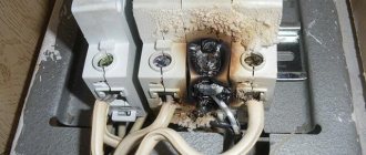
Finding the location of a short circuit or broken wire
So, we already know how to test wires with a multimeter. All that remains is to learn how to determine whether a wire is broken or a short circuit in the wall. At the moment, there are special devices for determining the location of cliffs. But their price is quite high and, if you do not plan to earn money from this, such a purchase is not advisable.
- As we have already said, there are now many methods and devices for determining the location of a wire break. I will give an example of just one, which I have been using for many years and which has never let me down.
Capacitive voltage indicator "FLUKE"
- It only requires a capacitive voltage indicator. I use it, but this issue is not important. The main thing is that it works correctly, and not from the slightest movement. There are those too. Its cost is not so high, and it is quite a necessary thing in the household.
- To determine the location of a phase wire break, you simply move it from the distribution box, where there is voltage, along the wall along the intended location of the wire. As long as there is voltage on the wire, the indicator lights up. At the site of the break it will go out.
- To determine the location of the break in the neutral wire, you just need to briefly make it phase. To do this, first of all, we relieve tension. Then we disconnect the phase neutral and protective wires and connect the neutral wire to the supply phase wire. After applying voltage, we proceed in the same way as when searching for a broken phase wire. Don't forget to restore the schema after searching.
- If there is a short circuit with a break, then disconnect all wires except the phase wire, and then apply voltage. Then we proceed in the same way as when searching for the location of a broken phase wire.
What to do if the multimeter does not have a dialing mode
Some budget electronic testers do not have a separate dialing mode with a sound alert, but they can also check the integrity of the circuit , but this is not so convenient.
For example, the fairly popular dt 830b does not have a buzzer, but there is a diode test mode, you can use it by observing the change in readings on the screen. The probes are connected in the same way as described above into the COM and V Ω mA .
If the readings on the screen during measurements differ from one, then there is an electrical connection in the area being tested. You can check the functionality of this method by connecting the probes; if everything is in order, then zeros should appear on the screen.
In multimeter models, where there are no additional functions at all, in particular in analog instruments, you can ring by switching the regulator to the resistance measurement mode - ohmmeter.
In this case, it is necessary to select the lowest available threshold - for example, 50 Ohms or 200 Ohms. Then measure according to the usual scheme described above and watch the changes in the readings on the screen - if there are changes, the circuit is intact. For home, everyday conditions, this is quite enough to find which wire is broken, determine the burnt track on the board, and much more.
That's all for me; in my opinion, this information is quite enough for anyone to learn how to dial with a multimeter, even without ever doing it before. If you still have questions or have healthy criticism or additions, be sure to write in the comments to the article, in addition, subscribe to our VKONTAKTE group - stay tuned for new materials.
In the following articles we will talk about other useful functions and ways to use a digital multimeter in everyday life, determine the phase and zero in an outlet, measure the voltage in the network and much more, stay tuned .
Checking the integrity of the insulation
This test is carried out at one end of the cable only. To do this, strip the conductors, turn the multimeter into resistance measurement mode, and select the megohm range.
Without touching the probes with your fingers, check with them whether there is a breakdown between the wires.
Due to the capacitance of the cable wires, the readings on the electronic display will initially change, but within a few seconds the capacitance will charge and the indicator should show one on the left side of the screen - this means that the resistance is so high that it is outside the measurement range.
If zero is established, this means that there is a short circuit between the wires. It happens that the multimeter shows some average value. If the cable is new, then it is of poor quality, and the moistened insulation leaks, or it may be affected by electromagnetic interference.
In this case, the device is switched to a lower range - hundreds of kilo-ohms, and the readings are monitored - in the case of electromagnetic interference, the value displayed on the display will constantly change, but if it is faulty insulation, the readings will be stable.
Basic units of measurement
Be sure to watch your hands when checking - they should not touch the probes, so as not to create errors in measurements. Often in this way you can check the serviceability of wiring located in a damp wall by connecting to wires that are known to be de-energized and not connected to electrical appliances.
Conductor continuity test
In a working cable, each core should conduct electric current, and there should be no short circuit between them.
If the cable has marked wires, then there is no need to identify the pairs of ends of each core. In this case, there is no need to pull the ends of the cable into one place, or pull the wire from the multimeter to the other end.
After checking the insulation for breakdown according to the method described above, it will be enough to strip and connect the wires at one end of the cable into one twist, and make a continuity test at the other.
The multimeter is switched to the resistance measurement mode, the lowest range is set - as a rule, it is 200 Ohms, or a special speaker icon specifically designed for dialing.
Multimeter in speaker switch position for dialing
Always check the multimeter itself before testing - to do this, connect two probes together - the tester should ring and show zero, after which you can take measurements.
To check, it will be enough to connect one probe to any wire, and the other one to go through all the wires one by one - they should ring everywhere, that is, the device should emit a sound signal if it has this option, or show a resistance close to zero.
Some long cables may have a resistance of several ohms - this is normal. If the device shows one on the right, it means there is a break somewhere in the tested wire.
How to test wiring between junction boxes
Very often it is necessary to find the ends of one conductor in a tangle of single-color wires in junction boxes. In this case, you cannot do without an additional conductor, with a length greater than the distance between the two boxes.
Cable testing is an essential tool for an electrician.
The standard and most common case is when there is no voltage in any outlet or lighting fixture, and sometimes in all of them at once. In this option, there is no choice - it is necessary to test the cable that powers the entire system, and then individual wires.
As a rule, in the distribution boxes of apartment buildings there is a tangle of unmarked and somehow insulated ends. Switches and sockets, especially in old houses, have long outlived their useful life. It is not easy to understand this intricacy and determine the specific place where the circuit break occurred. We have to check all the elements and re-label the cable cores.
Determining the presence of a short circuit
Knowing how to test wires with a multimeter, we can determine the location of the short circuit. After all, it does not always happen with sparks and fires. Often an electrical installation simply turns off for no apparent reason. And then it is imperative to check for the absence of a short circuit.
- First of all, let's figure out what a short circuit is. In our home network, as we have already said, there are three or two wires. One of them is phase, which has voltage. In a normal situation, there is no voltage on the neutral wire, because it is connected to the ground.
What is a short circuit?
- When the phase and neutral wires are connected through a resistance, for example, a light bulb, then it performs useful work - it shines. If the phase wire is connected to neutral, protective, or simply to ground without such resistance, then a short circuit occurs.
- Based on all this, it turns out that a short circuit is the presence of a circuit between the phase wire and the neutral wire. Therefore, in order to determine its presence, we just need to check the circuit between the phase wire and the neutral wire.
- To do this, first of all, we remove the voltage from the electrical network in which the search is to be carried out. But most likely you already have it without tension.
- The next important step is to turn off all switches and unscrew all lamps sitting without a switch. In addition, it is better to remove all household appliances from outlets. After all, they can distort the measurement results.
- Now, either in the distribution box or in a non-working socket, we check the circuit between the phase and neutral, and then the protective wire. The presence of this indicates the presence of a short circuit. Moreover, the presence of a circuit between the phase and protective wires may be a sign of a short circuit not with another wire, but with a grounded element of the house structure.
Note! Although you know how to test wires with a multimeter, this method does not always work. In rare cases, when there is a small contact resistance, the multimeter may not show it. The most reliable way is to measure the insulation resistance using a megohmmeter. This is a specialized device that gives accurate values. So for your home electrical network it should show at least 500 kOhm.
Megaohmmeter for 100, 250 and 500V
- But if you don’t have a megohmmeter, and you need to determine the presence of a short circuit with your own hands, then you can try one method. It is associated with a certain risk and therefore must be carried out in compliance with all rules.
- To do this, in the section of the circuit where there is supposedly a short circuit, after removing the voltage, we turn off and insulate the neutral and protective wires.
- Now, preferably wearing dielectric gloves, turn on the power supply for this group. If it turns off for us, then this is a clear sign of a short circuit of the phase wire to the ground or the structure of the house. If the machine does not turn off, then turn it off yourself.
- Now we remove the insulation from the ends of the neutral and protective wires. We separate them, completely eliminating contact between ourselves and the ground. Turn on the group power supply again. We check the presence of voltage on the neutral or protective wire. If there is voltage there, then there is a short circuit between this wire and the phase wire.
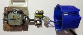
Checking wires from light bulbs and batteries
In order to assemble a device for testing wires and cables, it is not necessary to have any knowledge of electronics or radio engineering. No need to understand diodes, resistors or capacitors. Today I will show you how to make a wire harness from a regular battery and a light bulb.
So, the need for such a device arose when I disconnected distribution boxes. That is, it was necessary to determine where and where which wire goes.
Of course, when there are two or three wires in the circuit, it is not difficult to determine the direction of the lines in the box, but you must admit that if the wiring is done in dozens of directions, it is extremely not easy to do such work.
One day I was asked to assemble junction boxes. That is, the situation was such that people hired electricians to install electrical wiring. These electricians did some of the work, took money for it, and disappeared somewhere.
Of course, they did most of the work, namely, they laid the wires, brought all the ends into the sockets and distribution boxes, and so on in the little things, they installed spotlights. This is where all their work ended.
All that remained was to install sockets and switches and connect the wires in the junction boxes, which is what they called me for. The customer was in a panic and asked me to finish all the electrical work as soon as possible so that everything would finally work.
There were 8-10 wires going into the distribution boxes in different directions and it was easy to determine which one was going where, especially if you didn’t do the wiring. This is where the need for such a device as a wire tester became necessary.
This is a device that consists of a light bulb, a battery, probes and connecting wires between them.
6 Volt light bulb. Initially, the battery was installed on the crown at 9 Volts, but over time it became addictive and I installed four ordinary AA batteries of 1.5 Volts each in its case and connected them in series. That is, in total they also give 6 Volts.
The connecting wires between them are the most common, thin, flexible. It is very important here that their length is sufficient for continuity of wires over long distances.
For ease of measurement, an alligator clip was installed on one end of the probe.
This is convenient in the sense that, for example, the boxes are in different rooms and in order to ring the cable, we attach the crocodile in one box, go to another and check. That is, you can handle this kind of work yourself.
Special search devices
The best accuracy in detecting hidden wiring in walls is achieved by using special instruments and devices.
Electromagnetic detector
An effective way to detect hidden cables is to use special detectors.
The devices are capable of identifying live electrical wires with high accuracy. Therefore, before starting measurements, you should connect the load to a line with a power of at least 1 kW.
The detector is capable of detecting wires located at a depth of up to 7 cm from the wall surface. Modern models have several sensitivity modes. The measurement accuracy is reduced due to interference caused by high humidity or metal objects located in the wall.
Low-current wires are difficult to detect using electromagnetic detectors.
Indicator screwdriver
An inexpensive device for detecting wiring in the wall is an indicator screwdriver. Every electrician has this tool in their arsenal. When a screwdriver touches a phase cable on its body, the indicator lights up or a sound signal sounds. Transistor modifications can detect live cables without direct contact with them. Detection depth is up to 2 cm.
To find a hidden wire, you need to hold the tip of the screwdriver with your finger and run the other side over the intended location of the cable. When a voltage source is detected, a warning light on the housing lights up. Limitations of the method - you can only find a live cable; the depth of the wire should not be more than 2 cm.
Metal detector
The use of metal detectors gives good results. The operating principle of the device is simple. The device emits an alternating magnetic field. As a result, eddy currents are induced in the conductors. The metal detector sensor registers the secondary magnetic field that is generated. The devices are suitable in cases where you need to quickly examine a large area of the wall.