A metal hose is an electrical product used for laying wires and cables to protect them from external mechanical damage and environmental influences. In addition, a metal hose can be used to shield laid communications and prevent the formation of radio interference.
A metal hose is a corrugated pipe (corrugation) made of metal tape, which gives the product flexibility, and end/connecting fittings, which ensure the connection of individual sections into a single structure.
How to ground a metal hose
When a metal hose is grounded and how to do it, it is described in Chapter 1.7 of the Electrical Installation Code - “Grounding and protective electrical safety measures.”
The possibility of electric shock to a person upon contact with metal parts that are not normally energized is considered in the PUE to be indirect contact with live parts of this equipment.
The measure that provides the required protection determines the need to disconnect electrical equipment and lines from the power source by tripping the protection devices. To do this, the conductive parts must be connected to a solidly grounded neutral in TN type power supply systems, and grounded in IT and TT systems.
The connection of the protective conductor and the metal hose can be made in two ways:
1st method - using a clamp and a bolted connection.
In this case, a special clamp is used, the design of which includes a bolt (screw), through which the conductor is fastened, connecting the metal hose to the ground electrode.
2nd method - using soldering.
With this connection method, the conductor is connected directly to the surface of the metal hose.
Each of these methods has its own advantages and disadvantages.
- Advantages:
- for method 1: ease of installation;
- availability of execution, regardless of the location of the clamp installation.
for method 2:
- reliability of electrical contact.
- Flaws:
for method 1: electrical contact is less reliable than with another connection method.
for method 2:
- the difficulty of performing work in cramped installation conditions.
When performing work, the surface of the metal hose is cleaned of dirt and dust, after which it is cleaned using abrasive materials or tools (sandpaper, needle file, etc.), after which a clamp is installed or soldering is carried out.
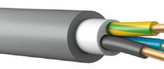
Copper or aluminum wires, as well as steel wire, can be used as a protective conductor.
The cross-section and diameter of such conductors are also regulated by the PUE:
- for aluminum wires - not less than 6.0 mm2;
- for copper conductors - not less than 4.0 mm2;
- for steel wire indoors - at least 5.0 mm;
- for steel wire outdoors - at least 6.0 mm.
The use of aluminum wires is allowed only if there is insulation; “bare” wires of this type are prohibited for making jumpers.
All connecting conductors must be equipped with lugs that are mounted by pressing, which ensures reliable contact when bolting the conductor to the grounding conductor and the grounded structure.
https://youtube.com/watch?v=UU4RLuuVd4E
To ground a metal hose or not to ground it?
Recently, during the design and construction of both industrial and civil facilities, there is increasingly a need to additionally protect laid cable communications from various destructive environmental influences. Such destructive effects on electrical and information cables can be divided into the following:
- Mechanical influences (shock, compressive, tensile loads);
- Chemical exposure from solid, liquid and gaseous aggressive media;
- Temperature effects of the environment;
- Exposure to direct sunlight;
- Exposure to flame in case of fire.
And despite all possible negative impacts, the cable line must remain safe throughout its entire service life for surrounding devices and systems, as well as for humans from electric shock. To solve such a complex problem, design and installation companies use various technically and economically sound solutions. One such solution is the use of flexible metal and composite pipe cable routing systems. Such systems include the well-known METAL HOSE in all variations of materials and coatings: bare metal hose (without coating), metal hose in a polymer (PVC or other) shell, metal hose in a thick-walled polymer shell.
Russian regulatory documents (PUE and GOST R IEC 61386 series) and international normative and technical documentation (IEC 61386) define the following series of requirements for such protective systems:
- Resistance to compressive loads;
- Resistance to shock loads;
- Resistance to tensile loads;
- Resistance to low and high temperature conditions;
- Resistance to bending loads;
- Continuity of the electrical circuit (grounding, metal connection);
- The electrical insulation resistance for a metal hose with a polymer coating is at least 100 MOhm.
- Resistance to penetration of solids and water (IP degree);
- Corrosion resistance;
- Resistance to flame propagation
Next, in a question-and-answer format, we will talk in more detail about how metal hoses ensure continuity of the electrical circuit, that is, simply about grounding such products as a metal hose.
What is the vital need for grounding a metal hose?
The first thing that can be noted is the protection of a person from electric shock when accidentally touching the metal parts of a metal hose with a damaged electrical cable. The second is potential equalization between connected equipment, which also protects humans. The third is to provide a path with low electrical resistance for short-circuit current, so that the protection device turns off the emergency section of the electrical installation in a short time, and the accident does not escalate, for example, into a fire.
What document determines the need to ground a metal hose?
The need to ensure continuity of the electrical circuit or grounding is defined in clause 1.7.76 and clause 1.7.77 of the Electrical Installation Rules to protect people from electric shock due to indirect contact. The requirements and test methods for grounding a metal hose (including those with a polymer coating) are described in more detail in clause 11 of GOST R IEC 61386.23-2015, namely, the transition resistance between the metal hose and the metal end fitting should be no more than 0.05 Ohm.
Who checks the quality of metal hose grounding and in what time frame?
These measurements and checks are carried out by specialists of the electrical laboratory; before commissioning of a construction, reconstruction or repair project, as well as during operation, periodic tests are carried out in accordance with the approved PPR schedule, but at least once every 3 years, according to GOST R 50571.28-2006 “Electrical installations” buildings. Part 7-710.62 Frequency of testing of electrical installations in operation"
Mounting coupling for metal hose
Installing metal hoses is not difficult. Fastening to surfaces is made possible by brackets, and individual structural elements are connected by couplings. The latter are distinguished by several characteristics:
- length;
- diameter of the connecting passage;
- material of manufacture;
- conditional working pressure;
- operating temperature.
The most common types of couplings are:
- pipe Serves to connect a metal hose and an electrical wiring pipe. Made of zinc alloy, equipped with a cylindrical thread;
- introductory The inlet coupling for a flexible metal hose allows its sealed insertion into the installation box. Self-extinguishing PVC is used for production.
- connecting. Made from zinc alloy for joining individual sections.
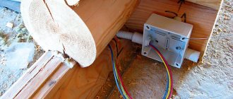
The input coupling ensures the safe operation of the most complex sections of electrical networks, where they are branched and special distribution boxes are installed. The coupling, without reducing the level of protection of the wires, leads the cable route into the junction box.
How to produce corrugated stainless steel hoses
Such flexible and sealed corrugated stainless steel metal hose designs are usually made using high quality steel or other metal. The design is equipped with connecting fittings made of the same material, which simplifies the joining of individual pipeline elements. The produced metal hose must receive a passport and a certificate.
Sealed stainless steel hoses are produced in several ways. The two most common are:
- Forming a seamless metal tube with a diameter of up to half a millimeter.
- By overlapping winding of the profile tape and connecting the edges of the corrugation using contact-roller welding.
The method of formation and the choice of metal for production determine what type of product will be given:
- annular;
- spiral.
The production of corrugated metal hoses includes reinforcement with steel wire. The spiral sleeve is reinforced in a spiral manner.
Manufactured products must be marked with nine meanings:
- year of issue;
- serial number;
- main technical characteristics.
Grounding of metal hose according to PUE - Fire safety
A metal hose is an electrical product used for laying wires and cables to protect them from external mechanical damage and environmental influences. In addition, a metal hose can be used to shield laid communications and prevent the formation of radio interference.
A metal hose is a corrugated pipe (corrugation) made of metal tape, which gives the product flexibility, and end/connecting fittings, which ensure the connection of individual sections into a single structure.
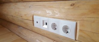
Cable laying in a metal hose
Cable laying in a metal hose
To protect wiring from exposure to dust, moisture, to protect from fire in the event of a short circuit, and from various mechanical damage when connecting electricity, a flexible metal pipe is used - a metal hose. It is very easy to install due to its large bending radius.
The metal hose is made of steel or galvanized tape, and all hoses have their own designations (markings). Marking RZ - for steel metal hoses, RZ-Ts for galvanized ones, sealed ones are marked with the abbreviation - RZTsP, hoses that have explosion protection are designated - VSG.
This product is used for laying electrical cables, as well as for computer network cables or communication cables.
Laying electrical cables in a metal sleeve
The metal sleeve acts as a protective case for the wire. The case is installed indoors, most often non-residential, because this type of installation on top of walls in a flexible pipe is less aesthetically pleasing. Metal flexible pipes are installed in industrial premises, basements, garages, and so on. Laying the cable in a metal hose provides reliable protection of the conductor, subject to compliance with all electrical installation rules (PUE). It is the rules for the design of electrical installations that determine the permissible conditions for the electrical installation of a metal product, how the cable should be laid in a metal hose, and determine the service life of the metal case. There are two ways to install the hose indoors. The first method is an open gasket, the second is a hidden one. In both the first and second cases, brackets or mounting clamps are used to fasten the sleeve. The brackets or clamps are attached to the mounting surface using self-tapping screws or nails.
One of the important criteria for installing a metal hose is the unacceptable laying of the hose on flammable surfaces and substrates made of wood, plastic, plasterboard, etc.
It is important to know that laying power wiring in a metal sleeve is allowed only when it is surrounded on all sides by fireproof materials. You can lay a metal conduit with an electrical cable inside yourself, but it is best to use the services of an electrical contractor
The work of an electrician will cost more, but the installation of the hose will be carried out in accordance with all the rules and established standards. It is very important how the cable is laid in the metal hose; the price of the specialist’s services will depend on the entire volume of work done. The price also depends on the cross-section and number of cable cores; the smaller the cross-section and number of cores, the cheaper. In total, all the work of an electrician to install a metal hose with wiring inside will cost from 130 to 1000 rubles.
In this article we will talk about a metal hose with PVC insulation.
Today, when progress and technology are developing by leaps and bounds, the issue of protecting electrical wiring and various cables during their installation has been resolved and quite successfully. The solution to this issue was a metal hose
for cables used in the installation of wiring, telephone lines, as well as in chemical and fuel industries.
The invention of the metal sleeve
takes us back to 1885, when the founder of
Witzenmann GmbH
, Heinrich Witzenmann, made a piece of jewelry - a necklace in the shape of a goose neck.
The invention and implementation of metal hoses
gave impetus to the development of the production of flexible metal elements.
The metal hose
is made from galvanized steel, which makes it resistant to corrosion.
A special characteristic of a metal hose
is that it does not support combustion, which occurs during a short circuit.
Application of metal hose:
The metal hose can be easily used in tropical and temperate climate zones. The operating pressure range is from 0.5 to 1.4 MPa. 300 degrees Celsius is the maximum temperature for metal hoses
with no seal or with an asbestos layer, in which it does not lose its properties.
There is also a cotton layer that ensures the operation of the metal hose
at a maximum of 100 degrees Celsius. Fire safety is another property that is ensured by the use of a metal hose since it is made from fireproof material.
VG kits, Flexible inputs
| They are used to make curved sections of pipe electrical wiring when inserting electrical equipment into the shell. | Used for on-site production of flexible bushings of the required length. |
Metalsleeve
is a flexible pipeline that is used to protect the laid cable line from external factors (mechanical, electrical, climatic).
Metal hose classifications:
- Types of castles
- Material of manufacture
- Seal material
- Coating material
Regarding the types of locks
, then
metal hoses
are divided into two types - these are sealed
metal hoses
- lock type
P1
,
P2
and unsealed
P3
(electrical hoses).
Types of manufacturing materials
- metal hose made of galvanized steel tape – R3-C
, - tinned steel tape – R3-SL
, - stainless tape – P3-N
, - aluminum tape – R3-Al
.
From the material of manufacture
Certain properties depend - these are mechanical strength, corrosion resistance, temperature range.
What depends on the seal material?
Seal material
determines the level of protection (IP) and operating temperature range.
As for the types of seal material
, there are only two of them - a sleeve
with a seal
and
without a seal
. Metal hoses with cotton and asbestos seals are very popular today; there are also seals made of nylon and other synthetic polyamides.
Metal hose coating material:
Metalsleeve
produced in a PVC shell - these are
NG
,
UHL
,
LSHF
, reinforced (increased strength), and there are also non-hermetic
metal hoses
of type
R3-C(A,X)
.
Metal hoses
are made of galvanized steel tape.
The polymer-coated hose is the most common and is used in many areas of construction. PVC sheath, which is located on the outside of the leaky metal hose
creates an additional level of protection, increased temperature range, increased fire protection and mechanical properties.
The color design of PVC is determined by the needs of the customer; the most common colors are black and gray. Today, there are several types of metal hoses in PVC coating (or in PVC insulation): MRPI
,
R3-TsP R3-SL-P
,
MPG
, electrical installation hose
ShEM
in various designs
(Ng/LsHF/, Uhl)
, etc.) . All this variety of metal hoses in PVC is widely used in the installation and construction of new facilities, as well as in the replacement of existing cable lines.
How to produce corrugated stainless steel hoses
Such flexible and sealed corrugated stainless steel metal hose designs are usually made using high quality steel or other metal. The design is equipped with connecting fittings made of the same material, which simplifies the joining of individual pipeline elements. The produced metal hose must receive a passport and a certificate.
Sealed stainless steel hoses are produced in several ways. The two most common are:
- Forming a seamless metal tube with a diameter of up to half a millimeter.
- By overlapping winding of the profile tape and connecting the edges of the corrugation using contact-roller welding.
The method of formation and the choice of metal for production determine what type of product will be given:
Sleeves are available with or without braiding, but even the presence of such a protective coating does not negate grounding
The production of corrugated metal hoses includes reinforcement with steel wire. The spiral sleeve is reinforced in a spiral manner.
Manufactured products must be marked with nine meanings:
- year of issue;
- serial number;
- main technical characteristics.
Clamp or solder
The contact point between the grounding conductors and the metal hose must have mechanical strength, reliability and minimal resistance. If you follow the correct installation technology, this result can be achieved in both ways.
Soldering will be more appropriate when implementing large-scale projects, since it does not require additional equipment, the use of soldering acids, and requires certain skills. Anyone can install the clamp using a regular screwdriver. Today the market offers products of various diameters and designs.
It is important to note that before installation, the surface of the metal hose must be cleaned to remove foreign substances and eliminate the oxide film. This procedure will significantly improve the quality of contact
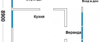
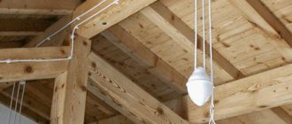
Grounding in a wooden house
A wooden house and electrical wiring can only be combined if all work is carried out by specialists and in accordance with current standards and requirements, otherwise the likelihood of natural materials catching fire due to the slightest spark is quite high.
In order to carry out grounding in your home, you should turn to the regulatory standards and look into the holy of holies of electricians PUE, find there a chapter entitled “grounding and protective electrical safety measures.” All subparagraphs should not be taken and re-read, since most of them are indicated for experienced specialists, or are an explanation of any terms, so here are a few basic ones that are important to take into account:
All electrical installations can be classified into several groups in terms of electrical safety:
- Installations above 1 kV with grounded neutral,
- installations above 1 kV with insulated neutral,
- Installations up to 1 kV with solidly grounded neutral,
- Installations up to 1 kV with insulated neutral.
This division is required only for the general perception of existing electrical installations; in Russia, a solidly grounded neutral is used for the construction of residential buildings and office premises.
If you have never heard such a concept, then here is the definition - this is the neutral of a generator or transformer, which, either through low resistance or directly, is connected to a grounding device.
You should also familiarize yourself with other definitions that can facilitate the process of installing electrical wiring in a wooden house:
- Ground electrode – a conductor or group of conductors located in direct contact with the ground.
- Working grounding is used to create favorable conditions for the operating process of an electrical installation.
- Grounding is called protective when it is used to ensure electrical safety.
Well, the most basic grounding rule, all from the same PUE: all group networks leading to residential apartments from the panels must be three-wire, where L is the phase, N is the neutral working conductor, and PE is the protective conductor. Combining protective and working conductors from different groups into one network is strictly prohibited.
By the way, if you analyze all the rules for constructing electrical installations, one conclusion suggests itself: all devices in the house, right down to the metal legs of the sofa and chair, should be connected to the neutral protective conductor.
What is a ground loop
What a ground electrode is has already been described; the circuit is the same, only the installation of the electrodes is carried out not in some selected place, but precisely along the contour of the building.
Here is an approximate grounding design that can be used for all types of houses, in fact, wooden ones:
- Three steel electrodes installed in the corners of the house at a depth of one and a half to two meters.
- They can be connected to each other using thin reinforcement.
- One of the selected electrodes serves as the main one; the ground wire will be attached to it.
- In cases where the circuit is located near the house, at a distance of 3 to 5 meters, it is connected to the metering panel with the same fittings.
Today, the grounding circuit has changed slightly: for wooden houses, a single-electrode one and a half meter copper-plated steel rod, consisting of several parts (up to 30 meters), is used. It is easy to install yourself, no need for the help of construction crews or any tools: having an electric hammer will help you solve the grounding problem.
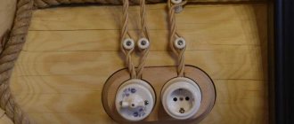
Street grounding, of course, reduces the chances of a house fire from any source, however, correctly connected phases in sockets and switches are also important in the process of electrical safety: if you doubt your abilities, call a specialist.
Grounding of metal hose according to PUE
Flexible metal hose is used to protect electrical wiring, cable networks, telecommunications and communication networks from rodents,…
Leave a comment
New on the forum
Latest Articles
Dismantling electrical wiring during repairs
Although electrical wiring is invisible, its importance is difficult to overestimate. As the number of energy consumers increases, the load on local networks increases. Many of them are not designed for operation in such conditions, and therefore begin to malfunction or even fail. Worn electrical wiring must be dismantled and replaced with a new one that is more efficient and reliable. In Moscow and the Moscow region […]
Installation method of roofing bitumen shingles and characteristics of materials
Bitumen shingles show themselves as a good material for creating roofing. It repels water well, is protected from freezing, ultraviolet rays, temperature changes, and biological effects. At the same time, the products are well suited for long-term use and make your building even more beautiful. In order for roofing bitumen shingles to show their best side, when laying it is necessary to comply with a number of requirements [...]
Agriculture equipment
Do you think that a person’s desire to surround himself with all kinds of helpers is a sign of laziness? No matter how it is. How will you feel if you find out that this is the driving force of evolution and progress? In fact, as soon as a person invented the digging stick - this is a primitive tool - his life became easier and his work more efficient. Exactly the same [...]
Imitation of natural stone in the ceramic tile industry
Ceramic tiles invariably imitated natural wood, concrete surfaces, metal and, of course, natural stone of various types. The line of any significant manufacturer necessarily includes a collection of ceramics that addresses the theme of marble, onyx, sandstone, slate or travertine. The Italian brand Atlas Concorde is one of the declared industry leaders. The factory’s assortment matrix contains many series related to [...]
Features of recycling fluorescent lamps
For a long time, the only source of artificial light was ordinary incandescent lamps. But in recent years, their efficiency, service life and efficiency have ceased to satisfy consumers. They have been replaced by fluorescent lamps of a discharge light source, which have a service life and light output several times greater than that of an incandescent lamp. When operating a simple lamp [...]
General concepts
For a clearer understanding and perception of the material, let’s consider two types of electrical networks. The external power supply network is the power lines (power lines) through which electricity is supplied to our house.
The photo below shows a section of the city's overhead power line that supplies residential buildings on my street. In a typical case, four insulators (rollers) mounted on a support are used. The three upper insulators are used for phase conductors (designated L1, L2, L3) and the bottom insulator is used for the neutral working conductor (designated N). With single-phase power supply, electricity is supplied to a residential building through two wires (the photo shows the outgoing line (L1 - N); with three-phase power supply, electricity is supplied to a residential building via 4 wires, i.e. all four wires are used.
Thus, a city overhead line (OHL) is a four-wire system (denoted by the combination of letters TN-C), in which conductor N (in modern terminology PEN) combines the functions of a working and protective conductor. This system (TN-C), despite its significant disadvantages, is approved for use for external supply networks. But according to current regulations, it cannot be used inside residential premises.
Internal (intra-house) electrical network is an electrical network laid inside a house, through which consumers in a residential building and outbuildings are provided with electricity, as well as lighting for the premises of the house and outbuildings.
As noted above, using the TN-C system inside residential buildings is prohibited. Only the TN-CS system is permitted for use. There are enough reasons:
- The inability of the TN-C system to provide the required electrical safety for the residents of the house and the safety of the building itself.
- Inability to use (at least fully) modern residual current devices.
- Inability to correctly and safely connect modern household appliances (TV, washing machine, refrigerator, etc.).
For clarity, let’s consider connecting modern household appliances with a three-pin plug (commonly called a Euro plug) to the indoor electrical network. With single-phase power supply to a residential building, two wires (phase and neutral) come into the house, as shown in the photo above. To correctly and safely connect household appliances equipped with a Euro plug, three wires are required: phase (L), neutral (N) and protective (PE). As shown in the photo below on the left.
Thus, if household appliances are connected to two-wire wiring, the equipment will work. This connection of modern household appliances is typical for old apartment buildings. But in this case there is a real threat of electric shock. Why? If we look at the connection diagram inside the device itself (washing machine, refrigerator, etc.), we will see that the third protective wire (PE), coming from the plug, is connected to the equipment body. The photo on the right shows the connection of the protective conductor inside the welding machine (circled in white). Other electrical equipment (washing machine, refrigerator, etc.) is connected in the same way. Due to this connection, the housing of the electrical device is always protected from the appearance of high (phase) voltage on it. Since in the event of damage (breakdown) of the insulation and the appearance of phase voltage on the device body, the circuit breaker will operate (either by short circuit current or by leakage current) and turn off the faulty device. This eliminates the possibility of electric shock to a person due to faulty equipment.
Unfortunately, in practice the situation is like this:
- People put up with (or are forced to put up with) the possible danger of electric shock when using an outdated (two-wire) electrical network in their home.
- They begin to try to “solve the problem” using traditional methods.
For example, on the Internet, an idea has been expressed to combine (connect) the contacts of the N and PE conductors in a socket. Thus, supposedly, the housing of electrical appliances will be neutralized, and the safety of residents will be ensured. This is strictly forbidden, as the likelihood of electric shock increases significantly. To understand why, I recommend looking at my article “Electrical work in the house - according to the British standard”.
Thus, for the correct safe connection of electrical equipment in a house with the possibility of using modern protective devices (RCDs), modernization (reconstruction) of the electrical network in a residential building is required.
Self-production
After preparing all the necessary materials and choosing a suitable place for arranging the grounding, you can proceed to the direct operations of assembling the grounding loop. At the preparatory stage, pipe or other profile sections are cut, the size of which is chosen to be 20-30 cm larger than the calculated one (this is necessary to compensate for the bending of the top of the workpiece when it is driven into the ground).
Simultaneously with the preparation of point pin grounding conductors, the stage of excavation begins, consisting of the preparation of grooves with beveled edges (to better retain the soil from shedding).
The order of operations performed during excavation work is as follows:
- First, the site for the future ground loop is prepared (cleared) and its markings are made;
- Then, using the already applied markings, grooves are dug with a depth of 70-80 cm and a width of about 50 cm (the depth is chosen to minimize corrosion of metal bonds);
- After this, the pins, cut to length, are driven in at the designated points so that about 20 cm protrude above the surface (see photo below);
Arrangement of a grounding loop
- Upon completion of the installation of all vertical elements, their upper parts are cut off, and the contact pads are thoroughly cleaned, after which metal connections are welded to them;
- After all welding seams have cooled, they are cleaned with a grinder and a grinding disc, and then painted with a special tar-based protective paint;
Note! Only areas of welded joints that are most susceptible to corrosion are painted.
- Next, from the short-circuit point closest to the residential building, a ditch is dug to the same depth that was dug under the metal connections (its width may be slightly smaller, since the connecting strip is made solid and does not require welding);
- Then a strip of metal with a standard size of at least 25x4 mm is laid in the prepared trench, which is subsequently welded to a pin or jumper (metal bond);
- At the final stage of work, near the wall of the house, the already laid metal strip is raised to a height of about 200 mm, where a busbar (wire) is connected to it by bolting or welding, going to the main distribution board (photo below).
Input of grounding into the house
To connect the finished grounding to the existing power supply circuit, you will need to familiarize yourself with the existing grounding schemes.
Entering the house
The circuit is connected to the grounding bus of the distribution system using a steel strip with a standard size of 24x4 mm or copper and flexible wire with a cross-section of 10 mm². In some cases, specifically specified in the PUE, it is allowed to use aluminum wire with a cross-section of 16 mm² for this purpose (see figure below).
Scheme of grounding installation in the panel
If there is a choice between the options proposed above, preference is given to copper wire, which has the most suitable characteristics for the task.
In the final part of the review, we draw the attention of users to the fact that it is not very easy to make a grounding loop with your own hands, since when carrying out this work, strict compliance with the requirements of the PUE is necessary. For those who are not completely confident in their abilities, there is always a “backup” way out - to invite representatives of an organization specializing in the manufacture of groundings
Rules for grounding pipelines
Grounding of pipelines is a mandatory measure, enshrined in the PUE. This is how you can increase the safety of their operation, because static electricity accumulates in pipe systems, plus there is always the possibility of lightning striking the pipes. The requirements of the rules for the construction of electrical installations are to provide grounding not only for external pipelines, but also for internal ones (technological and communication).
The PUE clearly regulates how pipelines should be grounded.
- Firstly, the pipe system must be a single continuous network connected into a single circuit.
- Secondly, pipelines must be connected to the grounding system at at least two points.
As for the first position, this does not mean that the pipeline system itself must be continuous. Here it will be enough to ensure the connection of sections or individual pipelines into one single network, for which so-called wafer jumpers are most often used. In fact, this is an ordinary copper wire of the brand either PVZ or PuGV. Fastening of jumpers to the pipeline is ensured by welding, bolting, or a grounding clamp for pipes is installed.
As for the second position, experts recommend not to scatter along the entire line of the technological chain, just to make a connection at the beginning and end of the circuit.
Circuit design
Components
The previously mentioned grounding resistance (Rз) of the circuit is the main parameter controlled at all stages of its operation and determines the effectiveness of its use. This value must be so small as to provide a free path for the emergency current tending to flow into the ground.
Note! The most important factor that has a decisive influence on the value of grounding resistance is the quality and condition of the soil at the site of the installation. Based on this, the charger in question or the ground loop of the charge circuit (which in our case is the same thing) must have a design that meets the following requirements:
Based on this, the charger in question or the ground loop of the charge circuit (which in our case is the same thing) must have a design that meets the following requirements:
- It must include a set of metal rods or pins with a length of at least 2 meters and a diameter of 10 to 25 millimeters;
- They are connected to each other (necessarily for welding) by plates of the same metal into a structure of a certain shape, forming a so-called “grounding conductor”;
- In addition, the device includes a supply copper busbar (also called electrical) with a cross-section determined by the type of equipment being protected and the magnitude of the drain current (see the table in the figure below).
Table of busbar sections
These component devices are necessary to connect the elements of the protected equipment with the descent (copper busbar).
Differences in device location
According to the provisions of the PUE, the protective circuit can have both external and internal design, and each of them is subject to special requirements. The latter establishes not only the permissible resistance of the ground loop, but also stipulates the conditions for measuring this parameter in each particular case (outside and inside the object).
When dividing grounding systems according to their location, it should be remembered that only for external structures the question of how the grounding resistance is normalized is correct, since it is usually absent indoors. Internal structures are characterized by wiring of electrical busbars along the entire perimeter of the premises, to which grounded parts of equipment and devices are connected through flexible copper conductors.
For structural elements grounded outside the facility, the concept of re-grounding resistance is introduced, which appeared as a result of the special organization of protection at the substation. The fact is that when forming a neutral protective conductor or a working conductor combined with it at the supply station, the neutral point of the equipment (step-down transformer, in particular) is already grounded once.
Therefore, when another local grounding is made at the opposite end of the same wire (usually a PEN or PE bus connected directly to the consumer panel), it can rightfully be called repeated. The organization of this type of protection is shown in the figure below.
Re-grounding
Important! The presence of local or repeated grounding allows you to insure yourself in case of damage to the protective neutral wire PEN (PE - in the TN-CS power supply system). Such a malfunction is usually found in technical literature under the name “zero burnout”
Such a malfunction is usually found in technical literature under the name “zero burnout.”
Mounting coupling for metal hose
Installing metal hoses is not difficult. Fastening to surfaces is made possible by brackets, and individual structural elements are connected by couplings. The latter are distinguished by several characteristics:
- length;
- diameter of the connecting passage;
- material of manufacture;
- conditional working pressure;
- operating temperature.
The most common types of couplings are:
- pipe Serves to connect a metal hose and an electrical wiring pipe. Made of zinc alloy, equipped with a cylindrical thread;
- introductory The inlet coupling for a flexible metal hose allows its sealed insertion into the installation box. Self-extinguishing PVC is used for production.
- connecting. Made from zinc alloy for joining individual sections.
The input coupling ensures the safe operation of the most complex sections of electrical networks, where they are branched and special distribution boxes are installed. The coupling, without reducing the level of protection of the wires, leads the cable route into the junction box.
You can ground a hose with an electrical cable passing through it using a steel clamp, which should wrap around the pipe as tightly as possible
Characteristics you need to know when using metal corrugated pipes
- Inner diameter. May differ significantly from the outside: it depends on the shape of the profile. If you know the diameter of the outer sheath of the cable, you need to multiply this figure by 1.5 or 2. When laying two cables in a sleeve, the diameter is added up.
- Conditional pass. This is actually the minimum diameter of the coil profile, which is taken into account when selecting connecting and input couplings for corrugated pipes.
- Outer diameter - the maximum size of the coil wave, according to the outer coating (if any).
- The tightness class is either according to the “IP” standard system - international, or according to the domestic classification: P1, P2, P3. The higher the number, the worse the tightness and the lower the cost.
- The tightness depends on the material of the interturn seal. The conditions of use also depend on it. Cotton - internal installation in rooms with a non-aggressive environment. Asbestos - operation in fire hazardous conditions, or with local heating. Polypropylene - outdoor use, or rooms with direct exposure to liquids.
- Climate class. Indicated in the product passport. Must be taken into account when laying. There are quite a lot of varieties: about 50 options.
- Passage of interference both from inside the corrugation and inside the sleeve. The undisputed leader in this discipline is the accordion-type sleeve. But a helical corrugation can also serve as an excellent shield if it is grounded.
The main parameters and components of the metal hose in the illustration:
1. The main profile is a coil made of metal.
2. Sealing material sealing the interturn grooves.
3. Outer shell made of polyvinyl chloride.
D. Outer diameter - measured along the outer shell.
d. Conditional diameter (when selected according to the diameter of the cable to be laid - internal diameter).
Restrictions on the use of metal hoses in wooden houses
When choosing an electrical wiring option, you need to know the restrictions established by the current PUE (Electrical Installation Rules) standards. The main rule regarding the issue under consideration is the following: laying a cable in a metal hose in a wooden house directly on a wood surface is simply prohibited. Moreover, it is valid even if the electrical wiring is grounded. The reasons for such strict restrictions are obvious and lie in two factors:
- Danger from rodents. These unwanted, but fairly frequent guests have a strange attraction to wiring. As a result, the metal hose is easily chewed through, which leads to a short circuit and, as a consequence, the risk of fire;
- High probability of mechanical damage by humans. Careless actions on the part of the inhabitants of the house, for example, a child, can lead to damage to the integrity of the product and the dire consequences described above.
Thus, the metal hose can be used in wooden buildings, subject to the specified restrictions. However, in practice it is actively used for the installation of both hidden and open wiring. This is especially true for metal hoses with PVC insulation, which have the highest performance characteristics.
Smallest cross-sections of protective conductors
| Section of phase conductors, mm2 | Minimum cross-section of protective conductors, mm2 |
| S ≤ 16 16 S ≤ 35 S > 35 | S 16 S /2 |
It is allowed, if necessary, to take the cross-section of the protective conductor less than required if it is calculated according to the formula (only for shutdown time ≤ 5 s
):
where S
— cross-sectional area of the protective conductor, mm2
;
I
- short circuit current, providing the time to disconnect the damaged circuit by the protective device in accordance with Table. 1.7.1 and 1.7.2 or in no more than 5 s
in accordance with 1.7.79,
A
;
t
— response time of the protective device, s
;
k
— coefficient, the value of which depends on the material of the protective conductor, its insulation, initial and final temperatures. k value
for protective conductors under various conditions are given in table. 1.7.6-1.7.9.
If the calculation results in a cross section different from that given in table. 1.7.5, then you should select the nearest larger value, and when obtaining a non-standard cross-section, use conductors of the nearest larger standard cross-section.
The maximum temperature values when determining the cross-section of the protective conductor should not exceed the maximum permissible heating temperatures of the conductors during a short circuit
in accordance with Ch. 1.4, and for electrical installations in explosive areas must comply with GOST 22782.0 “Explosion-proof electrical equipment. General technical requirements and test methods".
1.7.127. In all cases, the cross-section of copper protective conductors that are not part of the cable or laid not in a common shell (pipe, box, on the same tray) with phase conductors must be no less than:
2,5 mm2
— with mechanical protection;
4 mm2
- in the absence of mechanical protection.
The cross-section of separately laid protective aluminum conductors must be at least 16 mm2
1.7.128. In the TN
To meet the requirements of 1.7.88, it is recommended that neutral protective conductors be laid together or in close proximity to phase conductors.
Table 1.7.6
How to ground a metal hose
When a metal hose is grounded and how to do it, it is described in Chapter 1.7 of the Electrical Installation Code - “Grounding and protective electrical safety measures.”
The possibility of electric shock to a person upon contact with metal parts that are not normally energized is considered in the PUE to be indirect contact with live parts of this equipment.
The measure that provides the required protection determines the need to disconnect electrical equipment and lines from the power source by tripping the protection devices. To do this, the conductive parts must be connected to a solidly grounded neutral in TN type power supply systems, and grounded in IT and TT systems.
The connection of the protective conductor and the metal hose can be made in two ways:
1st method - using a clamp and a bolted connection.
In this case, a special clamp is used, the design of which includes a bolt (screw), through which the conductor is fastened, connecting the metal hose to the ground electrode.
2nd method - using soldering.
With this connection method, the conductor is connected directly to the surface of the metal hose.
Each of these methods has its own advantages and disadvantages.
- Advantages:
for method 1:
- ease of installation;
- availability of execution, regardless of the location of the clamp installation.
for method 2:
reliability of electrical contact.
- Flaws:
for method 1:
electrical contact is less reliable than with another connection method.
for method 2:
the difficulty of performing work in cramped installation conditions.
When performing work, the surface of the metal hose is cleaned of dirt and dust, after which it is cleaned using abrasive materials or tools (sandpaper, needle file, etc.), after which a clamp is installed or soldering is carried out.
Copper or aluminum wires, as well as steel wire, can be used as a protective conductor.
The cross-section and diameter of such conductors are also regulated by the PUE:
- for aluminum wires - not less than 6.0 mm2;
- for copper conductors - not less than 4.0 mm2;
- for steel wire indoors - at least 5.0 mm;
- for steel wire outdoors - at least 6.0 mm.
The use of aluminum wires is allowed only if there is insulation; “bare” wires of this type are prohibited for making jumpers.
All connecting conductors must be equipped with lugs that are mounted by pressing, which ensures reliable contact when bolting the conductor to the grounding conductor and the grounded structure.
What causes the need for grounding?
Grounding of electrical equipment, armored cables, as well as electrical wiring laid in a metal hose creates conditions for protection against electric shock in the event of a breakdown of the insulating sheath of the current-carrying elements in them.
When the cable insulation resistance drops below normal, the metal hose will be exposed to leakage current, which will go into the ground along the grounding jumper. If a person touches it, another circuit is created parallel to grounding, but since the resistance of the human body is much greater than that of the grounding jumper, an insignificant current will pass through it, which is safe for health and life. According to the PUE, when installing cable lines, the metal hose that serves as protection for the wiring must be grounded and this must be done in accordance with the requirements of regulatory documents (PUE clause 1.7.76, see Chapter 1.7).
Where in the PUE is it stated that the metal hose must be grounded?
Vasily Today we sealed the meter and the electrician made a comment that the metal hose of the input and output cables on the metering panel was not grounded! The shield is metal and mounted on a support! Where in the PUE is it stated that the metal hose must be grounded?
Answer: 1. Based on the PUE, table 2.1.2., it is prohibited to use a metal hose in an outdoor installation, since the wall thickness of the metal hose is less than 2 mm.
2. Installing a metering board on a support contradicts the requirements of the PUE, clause 1.5.27, since electricity meters must be placed in dry rooms with a temperature not lower than 0 °C.
3. In accordance with the PUE, clause 1.7.76., the metal hose must be connected to the grounding conductor.
PUE-6 Table 2.1.2 Selection of types of electrical wiring, installation methods and wires and cables
2. It is prohibited to use steel pipes and steel blind boxes with a wall thickness of 2 mm or less in damp, especially damp rooms and outdoor installations.
1.5.27 Meters must be located in dry rooms that are easily accessible for maintenance, in a place that is sufficiently free and not cramped for work, with a temperature in winter not lower than 0 °C. General industrial meters are not allowed to be installed in rooms where, due to production conditions, the temperature can often exceed +40 °C, as well as in rooms with aggressive environments. It is allowed to place meters in unheated rooms and corridors of switchgears of power plants and substations, as well as in outdoor cabinets. In this case, provision should be made for their stationary insulation for the winter through insulating cabinets, hoods with heating of the air inside them with an electric lamp or heating element to ensure a positive temperature inside the hood, but not higher than +20 ° C.
PUE-7 1.7.76 Protection requirements for indirect contact apply to:
1) housings of electrical machines, transformers, devices, lamps, etc.;
2) drives of electrical devices;
3) frames of distribution boards, control panels, panels and cabinets, as well as removable or opening parts, if the latter are equipped with electrical equipment with a voltage higher than 50 V AC or 120 V DC (in cases provided for by the relevant chapters of the PUE - higher than 25 V AC or 60 V VDC);
4) metal structures of switchgears, cable structures, cable couplings, shells and armor of control and power cables, sheaths of wires, sleeves and pipes of electrical wiring, shells and supporting structures of busbars (conductors), trays, boxes, strings, cables and strips on which reinforced cables and wires (except for strings, cables and strips along which cables with a neutralized or grounded metal sheath or armor are laid), as well as other metal structures on which electrical equipment is installed;
5) metal shells and armor of control and power cables and wires for voltages not exceeding those specified in 1.7.53, laid on common metal structures, including in common pipes, boxes, trays, etc., with cables and wires on higher voltages;
6) metal cases of mobile and portable electrical receivers;
7) electrical equipment installed on moving parts of machines, machines and mechanisms. When automatic power-off is used as a protective measure, these exposed conductive parts shall be connected to the solidly grounded neutral of the power supply in a TN system and earthed in IT and TT systems.
1.7.77 It is not necessary to intentionally connect to the source neutral in a TN system and ground in IT and TT systems:
1) housings of electrical equipment and devices installed on metal bases: structures, switchgears, switchboards, cabinets, frames of machines, machines and mechanisms connected to the neutral of the power source or grounded, while ensuring reliable electrical contact of these housings with the bases;
2) structures listed in 1.7.76, while ensuring reliable electrical contact between these structures and the electrical equipment installed on them, connected to the protective conductor;
3) removable or opening parts of the metal frames of switchgear chambers, cabinets, fences, etc., if electrical equipment is not installed on the removable (opening) parts or if the voltage of the installed electrical equipment does not exceed the values specified in 1.7.53;
4) reinforcement of insulators of overhead power lines and fasteners attached to it;
5) open conductive parts of electrical equipment with double insulation;
Metal sleeve Types of execution and application.
Metal hose is designed to protect insulated wires and cables in electrical installations and communication systems from mechanical damage and aggressive environmental influences. Metal hoses are used to protect rubber hoses and other similar products from mechanical damage, to meet fire safety requirements, for ventilation systems and gas removal.
Depending on the type of lock (P1 - P6), the metal hose is divided according to the method of operation. Type P3 (“er three”) is designed to protect wires, cables, etc. from mechanical damage.
Also, the metal hose is divided into non-sealed P3 (MP) and sealed in PVC insulation (MRPI). Depending on the material (galvanized, tinned or stainless steel tape), metal hoses are used in different climatic conditions. A non-hermetic metal hose can be additionally produced with a cotton or asbestos seal; the operating temperature of the product depends on this. A metal hose with a cotton seal is applicable in the temperature range from -600C to +1000C, and with an asbestos seal (or without a seal) from -600C to +3000C. Environmental protection degree: IP 42; compression resistance – at least 750 Newtons.
The metal hose in PVC insulation ensures waterproofness, dustproofness and resistance to environmental influences. PVC insulation meets fire safety requirements according to GOST R 53313-2009, combustion category PV-0. The Promrukav company produces metal hoses in PVC insulation for special purposes, which are used in various climatic conditions and ambient temperatures:
“Oil and petrol resistant” - UHL2, -300C to +600C;
“Frost-resistant” - UHL1, -700С to +600С;
“Oil and petrol resistant, frost resistant” - UHL1, -550C to +600C;
“Termostoyskiy” - UHL3, -500С to +1050С.
Despite the larger range of metal hoses, each type corresponds to a specific application. Thus, the metal hose “Oil-resistant, frost-resistant” is actively used in the oil and gas industry, and “Frost-resistant” is applicable in industrial refrigeration chambers. The P3 stainless steel metal hose tolerates high humidity and is suitable for tropical climates.
The most common question related to a metal hose is whether it needs to be grounded. According to PUE clause 1.7.76:
“The requirements for protection from indirect contact apply to:
1-4)…
5) metal shells and armor of control and power cables and wires for voltages not exceeding those specified in 1.7.53, laid on common metal structures, including in common pipes, boxes, trays, etc., with cables and wires on higher voltages."
In other words, the metal hose must be grounded. Grounding methods are varied and may include welding, soldering and the use of special clamps or couplings for grounding. PUE clause 1.7.139: “Connections and connections of grounding, protective conductors and conductors of the equalization and potential equalization system must be reliable and ensure continuity of the electrical circuit. It is recommended to make connections of steel conductors by welding. It is allowed to connect grounding and neutral protective conductors in indoor and outdoor installations without aggressive environments in other ways that meet the requirements of GOST 10434 “Electrical contact connections. General technical requirements" for class 2 connections.
Connections must be protected from corrosion and mechanical damage.
For bolted connections, provisions must be made to prevent contact loosening.”
MRPI has the necessary dielectric properties, which is confirmed by test report No. 085-07/10-ST.
Additionally, it is worth noting that according to the PUE, the use of metal hoses in hidden wiring of combustible structures is not allowed.
In conclusion, we can conclude that a metal hose is a universal means for protecting a cable line, depending on operating conditions and type of execution, in industrial and civil construction projects.
Electrical ground connection
A circuit with several grounds connected electrically ensures that different, sometimes conflicting, requirements for grounding devices are met. According to the PUE, grounding, like many other metal elements of the building, as well as equipment installed in it, must be connected by a potential equalization system. Potential equalization refers to the electrical connection of conductive parts to achieve equal potential. There are main and additional potential equalization systems. Grounding connections are connected to the main potential equalization system, that is, they are connected to each other through the main grounding bus. The wires connecting the grounding to this bus must be connected according to the radial principle, that is, one branch from the specified bus goes to only one ground.
In order to ensure safe operation of the entire system, it is very important to use the most reliable connection between the grounding and the main grounding bus, which will not be destroyed by lightning. To do this, you need to comply with the standards of PUE and GOST R 50571.5.54-2013 “Low-voltage electrical installations”
Part 5-54. Grounding devices, protective conductors and protective potential equalization conductors” regarding the cross-section of the potential equalization system wires and their connections to each other.
However, even a very high-quality potential equalization system cannot guarantee the absence of voltage surges in the network when lightning strikes a building. Therefore, along with well-designed grounding loops, surge noise protection devices (SPDs) will save you from problems. Such protection is multi-stage and selective in nature. That is, a set of surge protection devices must be installed at the facility, the selection of elements of which is not an easy task even for an experienced specialist. Fortunately, ready-made SPD kits are available for typical applications.
Main ground electrode
Ultimately, the entire chain of jumpers is connected to the main circuit. Often its role is played by already installed structures, which include reinforcement elements, metal pipes and other building structures. Connection to a specialized grounding circuit is also allowed.
For a number of reasons, it may be necessary to install a separate structure. The most convenient and technologically advanced solution today is modular pin systems - a set of conductive rods connected by threaded couplings. They are easy to install, have minimal cost and do an excellent job.
Following the above recommendations will allow you to get the desired result. It is important to take into account other rules and regulations for electrical installation processes. Remember that they do not only apply to large-scale government projects. When organizing a system on your own site, compliance with them plays a huge role, ensuring the effectiveness of grounding and safety for others.