Not to be confused with Effective antenna length.
| This article need additional quotes for verification . |
| Part of the series on |
| Antennas |
Common types
|
Components
|
Systems
|
Safety and Regulation
|
Radiation sources/regions
|
Characteristics
|
Methods
|
|
In telecommunications and electrical engineering, electrical length
(or
phase length
) refers to the length of an electrical conductor in terms of the phase shift introduced by transmission along that conductor[1] at a certain frequency.
Use of the term
Depending on the specific context, the term "electrical length" is used, rather than simply physical length, to include one or more of the following three concepts:
- When you are interested in the number of wavelengths, or phase, involved in the passage of a wave through a segment of a transmission line in particular, you can simply specify this electrical length without specifying the physical length, frequency, or speed factor. In this case, the electrical length is usually expressed as N
wavelength or as phase φ, expressed in degrees or radians. Thus, in a microstrip design it is possible to specify a shorted stub length of 60° phase, which will correspond to different physical lengths when applied to different frequencies. Or one might consider a 2-meter section of coaxial cable with a quarter-wavelength (90°) electrical length at 37.5 MHz and ask what its electrical length becomes when the circuit operates at a different frequency. - Due to the speed coefficient of a particular transmission line, for example, the time it takes a signal to travel through a cable of a certain length is equal to the time it takes to travel through a longer
distance when traveling at the speed of light. Thus, a pulse sent along a 2-meter section of coaxial cable (which has a speed factor of 67%) will reach the end of the coaxial cable at the same time as the same pulse that will arrive at the end of a bare wire 3 meters long (through which it travels at the speed of light) , and a 2 meter section of coaxial cable can be said to have an electrical length of 3 meters, or an electrical length of 1/2 wavelength at 50 MHz (since a 50 MHz radio wave has a wavelength of 6 meters). - Since resonant antennas are usually specified in terms of the electrical length of their conductors (e.g., a half-wave
dipole), achieving such an electrical length broadly equates to electrical resonance, i.e., purely resistive impedance at the antenna input, as is generally desired.
For example, an antenna that has been made too long will have inductive reactance, which can be corrected by physically shortening the antenna. Based on this understanding, common jargon in the antenna trade refers to achieving resonance (reactance suppression) at antenna terminals as electrically shortening
an antenna that is too long (or
electrically lengthening
an antenna that is too short) when the electrical matching network (or antenna tuner) has completed this task without
physically
changing the length of the antenna. Although the terminology is very imprecise, this usage is widespread, especially as applied to the use of a loading coil at the bottom of a short monopole (vertical, or whip antenna) to "electrically lengthen" it and achieve electrical resonance visible through the loading coil.
Dependence of the area of an electrical wire on its length
Typically, the wire cross-section is calculated based on power and length. That is, the longer the wiring, the greater the power loss due to the fact that the metal wire has resistance. And it increases as the cable length increases.
Since in private houses the electrical wiring loops are not so long, this calculation can be neglected. In industry, everything is different; the dependence of cable length and cross-section through power losses is obvious. Therefore, for information, let’s consider this calculation for a single-phase network.
Phase length
The first use of the term "electrical length" suggests a sine wave of some frequency or at least a narrowband waveform centered around some frequency .
.
The sine wave will repeat with a period T
=
1⁄f
.
The frequency w
will correspond to a specific wavelength λ along a specific conductor.
For conductors (such as bare wire or air-filled coax) that transmit signals at the speed of light c
, the wavelength is given by λ =
c
⁄
f
.
The distance L
along this conductor corresponds to
N
wavelengths, where
N
;
= L
⁄λ.
The figure on the right shows wave N
= 1.5 wavelengths.
The crest of the wave at the beginning of the graph, moving to the right, will appear at the end after time 1.5. T
.
The electrical length
of this segment is "1.5 wavelengths" or, expressed as a phase angle, "540°" (or 3π radians), where
N
wavelengths correspond to φ = 360°•
N
(or φ = 2π•
N
radians ). In radio frequency applications where delay is introduced due to a transmission line, the phase shift φ is often important, so defining a design in terms of phase or electrical length allows that design to be adapted to an arbitrary frequency using the wavelength λ applied to that frequency.
Reflections and reconciliation
Transmission line impedance is not designed to limit the flow of electrical current in the same way as a regular resistor. Characteristic impedance is simply the inevitable result of the interaction within a cable consisting of two conductors in close proximity to each other. The importance of characteristic impedance in the context of RF design is to prevent reflections and achieve maximum power transfer. This will be discussed in the next article.
Speed factor
In a transmission line, the signal travels at a speed controlled by the effective capacitance and inductance per unit length of the transmission line. Some transmission lines consist only of bare wires, in which case their signals travel at the speed of light. c
.
More often, the signal travels at a reduced speed κ c
, where κ is
the speed coefficient
, a number less than 1 that represents the ratio of this speed to the speed of light.[2][3]
Most transmission lines contain a dielectric material (insulator) that fills some or all of the space between the conductors. Relative dielectric constant or dielectric constant
The use of this material increases the distributed capacitance in the cable, which reduces the speed factor below unity.
It is also possible for κ to decrease due to the relative permeability ( μ r { displaystyle mu _ { text { r ))} ) of this material, which increases the distributed inductance, but this almost never happens. Now, if we fill the space with a dielectric with a relative permeability ϵ r { displaystyle epsilon _ { text {r))} , then the speed of a plane electromagnetic wave decreases by the speed coefficient: κ = v p c = 1 ϵ r μ r ≈ 1 ϵ r { displaystyle kappa = { frac {v_{p}} {c}} = { frac {1} { sqrt { epsilon _ { text {r}} mu _ { text {r}} }}} approximately { frac {1} { sqrt { epsilon _ { text {r}}}}}} .
This reduced speed factor can also be applied to the propagation of signals along wires immersed in a large space filled with this dielectric. However, when only part of the space around the conductors is filled with this dielectric, the wave speed decreases less. Part of the electromagnetic wave surrounding each conductor “feels” the action of the dielectric, and part is in free space. Then we can determine the effective relative dielectric constant
ϵ eff { displaystyle epsilon _ { text {eff}}} which then predicts the speed coefficient according to
κ = 1 ϵ eff { displaystyle kappa = { frac {1} { sqrt { epsilon _{ text {eff}}}}}}
ϵ eff { displaystyle epsilon _ { text {eff))} is calculated as the weighted average of the relative permittivity of free space (1) and the dielectric:
ϵ eff = ( 1 − F ) + F ϵ r { displaystyle epsilon _ { text {eff)) = (1-F) + F epsilon _ { text {r))}
where is the duty cycle
F expresses the effective fraction of space affected by the dielectric.
In the case of a coaxial cable, where the entire volume between the inner conductor and the screen is filled with a dielectric, the fill factor is equal to unity, since the electromagnetic wave is limited to this area. In other types of cable, such as double lead, the duty cycle can be much lower. In any case, any cable designed for radio frequency will have a speed factor (as well as a characteristic impedance) specified by the manufacturer. In the case of coaxial cable, where F = 1, the speed factor is determined solely by the type of dielectric used, as specified. Here.
For example, a typical speed factor for coaxial cable is 0.66, which corresponds to a dielectric constant of 2.25. Let's say we want to send a 30 MHz signal down a short section of such cable and delay it by a quarter wave (90°). In free space this frequency corresponds to a wavelength λ0= 10 m, so for a delay of 0.25 λ an electrical length
2.5 m. Using a speed factor of 0.66, we obtain
a physical
cable length of 1.67 m.
The speed factor also applies to antennas in cases where the antenna conductors are (partially) surrounded by dielectric. This especially applies to microstrip antennas such as the patch antenna. Microstrip waves are mainly affected by the dielectric of the circuit board underneath them, but also by the air above them (due to edge effects). Thus, their speed coefficients do not depend directly on the dielectric constant of the printed circuit board material, but on the effective
dielectric constant ϵ eff { displaystyle epsilon _ { text { eff))} which is often specified for the PCB material (or can be calculated). Note that the fill factor, and therefore ϵ eff { displaystyle epsilon _ { text { eff }}}, is somewhat dependent on the width of the trace compared to the thickness of the board.
DC cable measurement protocol forms and fiber optic measurement protocols can be downloaded from the Cable Measurement Protocol Forms page. There is also a self-filling protocol
A page describing the pulse method of cable measurement, as well as tables of shortening coefficient values, as well as related problems.
Reference data on communication cables TPP and KSPP. Standards for installed communication lines
Letter " C
" in the
KSPP
means "
Rural
".
About the design features and basic brands of this type of cable on the page → Rural communication cables
.
Many standards and parameters can be found in the “Guide to the construction of linear structures of local communication networks, M., 2005”
. The standards for electrical parameters from this book are on the page of the same name. The remaining standards can be found in other sections of the “Manual...” the table of contents of which is on the pages Manual I and Manual II.
The site also contains a manual for the operation of line-cable structures of local communication networks. The bulk of reference materials is located in the appendices of this book.
Taken from OST 45.83-96
, although almost the same can be found in the general instructions for the construction of hydraulic structures for 1978 and in the OSTs of other CIS countries:
5 Electrical standards for subscriber lines of city telephone networks
5.1 The electrical resistance of 1 km of subscriber cable line circuits to direct current at an ambient temperature of 20°C, depending on the cable used, is given in Table 1.
| Cable brand for AL GTS | Core diameter, mm | Electrical resistance of 1 km of circuit, Ohm, no more |
| TPP, TPPep, TPPZ, TPPepZ, TPPB, TPPepB, TPPZB, TPPBG, TPPepBG, TPPBbShp, TPPepBbShp, TPPZBbShp, TPPZepBbShp, TPPt | 0,32 0,40 0,50 0,64 0,70 | 458,0 296,0 192,0 116,0 96,0 |
| TPV, TPZBG | 0,32 0,40 0,50 0,64 0,70 | 458,0 296,0 192,0 116,0 96,0 |
| TG, TB, TBG, TK | 0,40 0,50 0,64 0,70 | 296,0 192,0 116,0 96,0 |
| TStShp, TAShp | 0,50 0,70 | 192,0 96,0 |
| TSV | 0,40 0,50 | 296,0 192,0 |
5.2 The value of the asymmetry of the resistance of the AL GTS cores to direct current should be no more than 0.5% of the circuit resistance.
5.3 The electrical insulation resistance of 1 km of AL GTS cores under normal climatic conditions, depending on the cable brand, must meet the requirements given in Table 2.
| Cable brand for AL GTS | Electrical insulation resistance of 1 km of cores, MOhm, not less | |||
| Line service life | ||||
| commissioning* | up to 5 years | up to 10 years | over 15 years old | |
| TPP, TPPep, TPPB, TPPepB, TPPBG, TPPepBG, TPPBbShp, TPPepBbShp, TPPZepBbShp | 5000 | 1000 | 500 | 300 |
| TPPZ, TPPZB, TPPZepB | 5000 | 1000 | 800 | 500 |
| TG, TB, TBG, TC for cores with insulation: tubular-paper, porous-paper | 5000 4000 | 1000 1000 | 400 400 | 200 200 |
| * - standards are established for lines without terminal devices | ||||
5.4 The attenuation value of AL GTS circuits at a frequency of 1000 Hz should be no more than: 6.0 dB - for cables with core diameters of 0.4 and 0.5 mm; 5.0 dB - for cables with a core diameter of 0.32 mm.
5.5 The value of the transition attenuation between the AL circuits of the GTS at the near end at a frequency of 1000 Hz must be at least 69.5 dB. ...
Appendix A (reference)
Electrical standards for structural elements of AL GTS Table A.1 Electrical characteristics of AL GTS taking into account the service life
| Cable brand for PBX | Core insulation resistance, MOhm | Working capacity, nf/km | ||||
| 5 years | 10 years | 15 years | 5 years | 10 years | 15 years | |
| Chamber of Commerce and Industry TG TPPP | 1000 1000 1000 | 500 500 800 | 200 200 500 | 50 52 50 | 55 55 50 | 60 60 55 |
Isolation with end devices
, that is,
with plinths
, must be at least
1000 MOhm
, regardless of the cable length.
This standard is on the page “DC Electrical Standards for Unsealed Cable, Overhead and Mixed Lines of Local Communication Networks in Operation” in Table P.4.2 Electrical Insulation Resistance of the Conducting Cores of a Cable Line at a Temperature of Plus 20 °C (read note) from “Rules for the maintenance and repair of cable, overhead and mixed local communication networks.
1996" .
It is not always printed in new instructions, but those who constantly work with this know that if the cable is not damaged, the greatest drop in insulation is on the plinths (usually damp).
• The topic of measuring CLS insulation is informally, but taking into account experience, covered on the page → Insulation standard for a cable communication line • About the reasons for damping of plinths → Why do plinths get damp in SR, how to dry them, how to increase the insulation • There is a section on terminal devices used in wired communication on the site « Termination devices for copper communication cables
", beginning: → Thunderstripe. Crossover terminals
Taken from OST 45.83-965.7:
Electrical standards for AL STS from bottom-quadruple communication cables type KSPZP 5.7.1 Electrical resistance of 1 km of AL STS circuit to direct current at an ambient temperature of 20 ° C, depending on the brand of cable used, is given in Table 4. Table 4
| Cable brand for AL STS | Core diameter, mm | Electrical resistance 1km circuit.Ohm |
| KSPZP | 0,64 | 116,0 |
| KSPP, KSPZP, KSPPB, KSPZPB, KSPPt, KSPZPt, KSPZPK | 0,90 | 56,8 |
5.7.2 The value of the asymmetry of the resistance of the DC cores of the cable AL STS circuit should be no more than 0.5% of the circuit resistance.
5.7.3 The operating electrical capacitance of 1 km of circuit should be no more than: 35nF - for KSPZP 1x4x0.64; 38 nF - for KSPZP (KSPP) 1x4x0.9.
5.7.4 The electrical insulation resistance of 1 km of AL STO cable cores, depending on the cable brand and service life, is given in Table 5.
Table 5
| Cable brand for AL STS | Electrical insulation resistance of 1 km circuit, MOhm, not less | ||||
| Line service life | |||||
| commissioning * | up to 5 years | up to 10 years | up to 15 years | over 15 years | |
| KSPP, KSPPB, KSPPZ | 10000 | 10000 | 8000 | 5000 | 3000 |
| KSPZP, KSPZPB, KSPZPt, KTPZBbShp | 10000 | 10000 | 10000 | 10000 | 8000 |
| * - standards are established for lines without terminal devices | |||||
5.7.5 The electrical resistance of the insulation (sheath, hose) of 1 km of plastic cable screen relative to the ground during the entire service life must be at least 1.0 MOhm.
The insulation resistance of the protective polyethylene hose (for cables in steel or aluminum sheath) is 5 MOhm/km. [General instructions for the construction of HP GTS, 1978]. This value now extends to the insulation of the TPP screen
and even for
the armor of a fiber optic cable
, although a caveat has appeared that if it is difficult to find insulation damage, then a value of 1 MOhm/km is allowed.
Mention " 5 MOhm/km
"is in the "LKSMSS Operation Manual". For KSPP and KSPZP in table P1.3 Electrical parameters of cables of KSPP and KSPZP types. For KTPZBBbShp in table P1.4 Electrical parameters of low-pair cables of the KTPZBBbShp brand.
Electrical characteristics of communication cables TPP, KSPP
Characteristics of TPP brand cables
Electrical characteristics of cables at construction lengths at a temperature of +20°C
| Characteristic name | Length, m | Frequency, kHz | Chamber of Commerce and Industry with core diameter, mm | |||
| 0.32 | 0.4 | 0.5 | 0.7 | |||
| Resistance of 2 conductors (loop), Ohm, no more | 1000 | D.C. | 432±36 | 278±12 | 180±12 | 90±6 |
| Insulation resistance of cores in relation to the screen, MOhm, not less | 1000 | D.C. | 5000 | 5000 | 5000 | 5000 |
| Working capacity of a pair, nF, no more | 1000 | 0.8 | 45±8 | 45±8 | 45±8 | 45±8 |
| Test voltage for checking insulation strength for 2 min. between the bundle of all cores and the screen, B | 1000 | 0.05 | 1000 | 1000 | 1000 | 1000 |
| Test voltage to check the strength of the insulation for 2 minutes. between the cores of working pairs, V | 1000 | 0.05 | 1000 | 500 | 500 | 500 |
| Pair attenuation coefficient, dB, no more | 1000 | 0.8 | 1.74 | 1.566 | 1.262 | 0.86 |
| 250 | — | 11.12 | 9.22 | 6.35 | ||
| Wave impedance module, Ohm | — | 0.8 | 1350 | 980 | 895 | 670 |
| 550 | — | 132 | 112 | 112 | ||
Frequency characteristics of bunched cables at a temperature of +20°C
| Frequency, kHz | Solid polyethylene insulation, core diameter 0.4, quadruple twist | Solid polyethylene insulation, core diameter 0.5, twisted in pairs | Solid polyethylene insulation, core diameter 0.5, quadruple twist | Solid polyethylene insulation, core diameter 0.7, quadruple twist | ||||
| Coef. attenuation, dB/km | Wave impedance module, Ohm | Coef. attenuation, dB/km | Wave impedance module, Ohm | Coef. attenuation, dB/km | Wave impedance module, Ohm | Coef. attenuation, dB/km | Wave impedance module, Ohm | |
| 0.8 | 1.44 | 1164 | 1.23 | 893 | 1.16 | 947 | 0.82 | 676 |
| 3.0 | 2.73 | 602 | 2.38 | 461 | 2.18 | 488 | 1.51 | 351 |
| 5 | 3.51 | 467.0 | 2.95 | 356.5 | 2.74 | 375.0 | 1.87 | 275.0 |
| 10 | 4.72 | 331.4 | 3.96 | 255.5 | 3.65 | 272.1 | 2.38 | 201.0 |
| 20 | 6.17 | 238.5 | 5.09 | 185.5 | 4.65 | 200.5 | 2.78 | 158.2 |
| 50 | 8.02 | 168.6 | 6.37 | 135.3 | 5.71 | 152.8 | 3.45 | 138.1 |
| 100 | 9.07 | 145.3 | 7.15 | 121.8 | 6.48 | 139.8 | 4.21 | 132.9 |
| 150 | 9.74 | 139.4 | 7.64 | 117.4 | 7.00 | 137.0 | 4.88 | 131.5 |
| 200 | 10.49 | 137.1 | 8.37 | 116.0 | 7.87 | 135.2 | 5.67 | 130.4 |
| 250 | 11.12 | 135.7 | 9.22 | 115.1 | 8.70 | 134.5 | 6.35 | 129.0 |
| 300 | 12.08 | 135.0 | 10.01 | 114.3 | 9.48 | 133.8 | 6.96 | 128.0 |
| 350 | 12.70 | 134.0 | 10.70 | 113.6 | 10.08 | 133.0 | 7.48 | 127.0 |
| 400 | 13.57 | 133.7 | 11.31 | 113.0 | 10.79 | 132.5 | 8.11 | 125.0 |
| 500 | 15.05 | 132.9 | 12.62 | 112.4 | 11.75 | 131.8 | 8.96 | 125.0 |
| 600 | 16.31 | 131.5 | 13.75 | 111.8 | 12.81 | 131.2 | 9.79 | 125.0 |
| 700 | 17.40 | 131.6 | 14.70 | 111.1 | 13.92 | 130.8 | 10.61 | 125.0 |
| 800 | 18.53 | 131.3 | 15.66 | 110.5 | 14.79 | 130.0 | 11.31 | 124.8 |
| 1000 | 20.71 | 130.5 | 17.40 | 109.9 | 16.18 | 129.7 | 12.62 | 124.0 |
| 1500 | 23.93 | 129.9 | 21.06 | 108.5 | 20.01 | 128.9 | 15.68 | 123.1 |
| 2000 | 28.58 | 129.5 | 23.88 | 107.2 | 22.62 | 127.0 | 18.28 | 121.5 |
| 2500 | 32.07 | 128.3 | 26.36 | 106.5 | 24.88 | 126.5 | 20.53 | 121.0 |
Note. The spread of the attenuation coefficient values over the entire frequency spectrum is ±5%, and the wave impedance modulus is ±6%.
KSPP cable parameters
Letter " C
" in the
KSPP
means "
Rural
".
Available in the Operating Manual for line-cable structures of local communication networks on page → Electrical parameters of cables of the KSPP and KSPZP types.
In the appendices to the Operating Manual for line-cable structures of local communication networks there are also design data for the most common communication cables
Appendix 1. Electrical parameters of cables and wires of local communication networks Table A1.1. Electrical parameters of telephone cables of types T, TP and STPA in metal and plastic sheaths Table A1.2. Electrical parameters of cables with cord-paper and cord-polystyrene insulation in a metal sheath Table A1.3. Electrical parameters of cables of KSPP and KSPZP types. Table A1.4. Electrical parameters of low-pair cables of the KTPZBbShp brand Table P1.5. Electrical parameters of cables and wires of TSV, PKSV, LTV brands Table A1.6. Electrical parameters of single-pair cables and wires Appendix 2. Design parameters of cables and wires for local communication networks Table A2.1. Design parameters of multi-pair cables Table A2.2. Design characteristics of single-quad, low-pair, single-pair cables and wires Table A2.3. Maximum outer diameter and estimated weight of PKSV grade wire Appendix 3 Outer diameters of cables used in local communication networks Table A3.1. Outer diameters of type T cables Table A3.2. External diameters of cables Table P3.3. Outer diameters of TP type cables filled with hydrophobic mass Table A3.4. External diameters of cables in a polyvinyl chloride sheath Table A3.5. Outer diameters of cables with film-porous polyethylene insulation of cores in a polyethylene sheath of the TPppZP brand Table A3.6. Outer diameters of STPA type cables Table P3.7. Nominal outer diameter of cable type TZ with conductors with a nominal diameter of 0.9 mm Table P3.8. Nominal outer diameter of TZ type cables with conductors with a nominal diameter of 1.2 mm Table P3.9. Outer diameters of MKS type cables with a conductor diameter of 1.2 mm Appendix 4. Design data and optical parameters of optical cables used in local communication networks Table A4.1. Parameters of linear optical cables Table A4.2. Parameters of station optical cables Table A4.3. External diameter of cables with optical modules with a nominal diameter of 1.8 mm Table A4.4. External diameter of cables with optical modules with a nominal diameter of 2.2 mm Table A4.5. External diameter of cables with optical modules with a nominal diameter of 2.5 mm Table P4.6. Weight of cables with optical modules with a nominal diameter of 1.8 mm, kg/km Table A4.7. Weight of cables with optical modules with a nominal diameter of 2.2 mm, kg/km Table A4.8. Weight of cables with optical modules with a nominal diameter of 2.5 mm, kg/km
In the appendices to the “Rules for the maintenance and repair of cable, overhead and mixed local communication networks”
Appendix 1. Characteristics of linear wire and wires used on lines of local communication networks Appendix 2. Characteristics of supports used on pole lines of local communication networks Appendix 3. Overall dimensions of reinforced concrete attachments Appendix 4. DC electrical standards for unsealed cables in use, overhead and mixed lines of local communication networks Appendix 5. Electrical standards on alternating current for unsealed, in operation, cable, overhead and mixed lines of local communication networks Appendix 6. Standards of electrical characteristics of the amplifying (regeneration) sections of cable connecting (interstation) lines of STS, sealed by transmission systems (at a temperature of 20 ° C) Appendix 7. Minimum permissible distances between a communication cable laid in the ground, or a cable duct and other structures Appendix 8. Dimensions of overhead cables Appendix 9. Overall dimensions of overhead lines of local communication networks Appendix 10. Normal and maximum span lengths of overhead lines of local communication networks Appendix 11. Burying depth of supports and extensions of pole lines of local communication networks Appendix 12. Wire sag lines Appendix 13. Norms of annual consumption of materials, fittings and equipment for operational maintenance and routine repairs of pole lines Appendix 14. Norms of annual consumption of fittings and materials for operational maintenance and routine repairs of rack lines Appendix 15. List of tools and equipment for electricians servicing overhead lines Appendix 16. List of basic tools for a district electrician Appendix 17. Form N 8 (work order) Appendix 18. Form of act accepting work on routine repairs of linear structures
On the protection of communication lines from interference and interference, see the page “Protection of pairs and quads in communication cables”
Antennas
Although there are certain broadband antenna designs, many antennas are classified as resonant and operate by design at a specific frequency. This is especially true for broadcast stations and communications systems that are limited to a single frequency or narrow band. This includes dipole and monopole antennas and all designs based on them (Yagi, dipole or monopole arrays, folded dipole, etc.). Besides the directive gain of beam antennas suffering from the design frequency, the antenna feed point impedance is very sensitive to frequency shift. Especially for transmission, the antenna is often designed to operate at a resonant frequency. At the resonant frequency, this impedance is by definition a pure resistance which matches that of the characteristic impedance of the transmission line and the output (or input) impedance of the transmitter (or receiver). At frequencies far from the resonant frequency, the impedance includes some reactance (capacitance or inductance). Perhaps an antenna tuner should be used to cancel this reactance (and change the resistance to match the transmission line), however this is often avoided as an additional complication (and needs to be controlled at the antenna side of the transmission line).
The resonance condition in a monopole antenna for the element must be an odd multiple of a quarter of the wavelength, λ
/ 4. In a dipole antenna, both driven conductors must be of such length that the total length of the dipole is
(2N + 1) λ
/2.
The electrical length of an antenna element is usually different from its physical length.[ need a better source
][4][5][6]For example, increasing the diameter of the conductor or the presence of metal objects nearby will reduce the speed of the waves in the element, increasing the electrical length.[7][8]
An antenna whose length is less than its resonant length is described as " electrically short
“,[9] and exhibits capacitance.
Similarly, an antenna whose length exceeds its resonant length is described as " electrically long
" and exhibits inductive reactance.
Change in electrical length under load
Load coil in a mobile phone antenna mounted on the roof of a car.
The coil allows the antenna to be shorter than a quarter wavelength and still remain resonant. The effective electrical length of an antenna can be changed without changing its physical length by adding reactance (inductance or capacitance) in series with it.[10] This is called lumped impedance matching
or
download
.
For example, a monopole antenna such as a metal rod with one end will be resonant when its electrical length is equal to a quarter of the wavelength, λ
/ 4 frequencies used.
If the antenna is shorter than a quarter wavelength, the feedpoint impedance will include capacitance; this causes reflections on the feed and mismatch at the transmitter or receiver, even if the resistive component of the impedance is correct. To neutralize capacitive reactance, an inductance called a loading coil is inserted between the feeder and the antenna terminal. Selecting an inductance with the same reactance as the (negative) capacitive reactance seen at the antenna terminal cancels that capacitance and the antenna system
(antenna and coil) will be resonant again. The power line has purely resistive impedance. Because an antenna that was too short now appears to be resonant, adding a loading coil is sometimes called "electrically extending" the antenna.
Similarly, the feedpoint impedance of a monopole antenna is greater than λ
/4 (or a dipole with arms longer than
λ
/4) will include inductive reactance. A capacitor in series with the antenna can neutralize this reactance to make it resonant, which can be called "electrical shortening" of the antenna.
Inductive loads are widely used to reduce the length of whip antennas in portable radios such as walkie-talkies and short-wave antennas on automobiles to meet physical requirements.
A vertical antenna that can have any desired height: approximately less than half the wavelength of the frequency at which the antenna operates. These antennas can work as transmitting or receiving antennas.
Advantages
Electrical extension allows shorter antennas to be created. Used in particular for antennas for VLF, long-wave and medium-wave transmitters. Because these radio waves range in length from several hundred meters to many kilometers, radiator masts of the required height are economically impossible to implement. It is also widely used for whip antennas on portable devices such as walkie-talkies to allow antennas much shorter than the standard quarter wavelength to be used. The most widely used example is the rubber duck antenna.
Flaws
Electrical extension reduces the antenna's throughput unless other phase control measures are taken. An electrically extended antenna is less efficient than an equivalent full-size antenna.
Technical implementation
There are two possibilities for implementing electrical extension.
- inclusion of induction coils in series with an antenna
- switching metal surfaces, known as roof capacitance, at the ends of the antennas, which form capacitors to the globe.
Often both indicators are combined. Coils connected in series sometimes need to be placed in the middle of the antenna structure. The cabin installed at a height of 150 meters on the Blosenbergturm in Böromünster is such a design in which an extension coil is installed to power the top of the tower (a ring capacitor is additionally installed on the roof of the Blosenbergturm on the roof)
Statement
In the transmitting antennas of transmitters operating at frequencies below the long-wave radio broadcasting range, electrical extension is always used. It is often used in broadcast antennas of long-wave radio broadcasting stations. However, electrical extension is widely used for NDB transmit antennas because they use antennas whose height is significantly less than a quarter of the emitted wavelength.
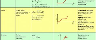
- On the left are characteristics constructed on the basis of experimentally obtained data on coordinates with a logarithmic abscissa. On the right is an antenna with increased effective inductance between the two points, in accordance with the well-known operation of shunt-tuned circuits, adjusted slightly off-resonance.
How to find the length of a conductor
Author Olga Gromysheva asked a question in the Natural Sciences
What is the formula for finding the length of a conductor? and got the best answer
Answer from Kraboch [guru] and the formula is R=p*L /S. So calculate L from here
Checking for long-term permissible current and voltage loss in more detail.
Finding the length of the conductor is very simple - just measure it. However, if the conductor is not accessible or is very long, then measuring it directly can be very difficult.
- construction tape; — ammeter (tester); - caliper; - table of electrical conductivity of metals.
To find the length of the conductor, measure the lengths of its individual sections with a tape measure and add them up. This method is suitable for open wiring and wire measurements in temporary cable connections.
If the electrical wiring is hidden, then use the appropriate wiring diagram to find the exact length of the conductor. If there is no such diagram, then try to indirectly restore the placement of the wires based on the position of sockets, switches, junction boxes, etc. signs.
Please note an important rule for electricians: all wires must be laid strictly horizontally or vertically. Moreover, horizontal sections of wire, as a rule, run along the upper edge of the wall (under the ceiling). However, only a special device or an experienced electrician can determine the actual location of the wires.
If it is impossible to restore the trajectory of hidden electrical wiring, then measure the electrical resistance of individual sections of the conductor. For calculations, also specify the cross-section of the wire and the material from which it consists. As a rule, this is copper or aluminum. Since the formula for calculating resistance is: R =? * L * s, then the length of the conductor can be calculated using the formula:
where: L – conductor length, R – conductor resistance, ? – resistivity of the material from which the conductor is made, s – cross-sectional area of the conductor.
When calculating the conductor length, consider the following parameters and ratios.
The resistivity of copper wire is 0.0154 - 0.0174 ohms, aluminum: 0.0262 - 0.0278 ohms. (If the length of the conductor is 1 meter and the cross-section is 1 mm?).
The cross section of the conductor is:
Where: ? - the number "pi", approximately equal to 3.14, D - the diameter of the wire (which can be easily measured with a caliper).
If the wire is wound into a coil, then determine the length of one turn and multiply by the number of turns.
If the coil has a round cross-section, then measure the diameter of the coil (the average diameter of the winding if it is multilayer). Then multiply the diameter by pi and the number of turns:
d is the diameter of the coil, n is the number of turns of wire.
Specific resistance is a characteristic of the material from which the conductor is made.
The electrical resistance of a conductor is directly proportional to the product of the resistivity of the material from which the conductor is made and its length, and inversely proportional to its cross-section.
| electrical resistance of the conductor, | Ohm |
| resistivity of the conductor material, | Ohm m |
| conductor length, | Meter |
| conductor cross section, | Meter2 |
SI unit of resistivity
Specific resistance ρ depends on temperature.
Recommendations
- Ron Schmitt, Electromagnetism Explained [electronic resource]: A guide to wireless/RF, EMC, and high-speed electronics.
- Carr, Joseph J. (1997). Microwave and wireless technologies
. Newnes. paragraph 51. ISBN 0750697075. - Amlaner, Charles J. Jr. (March 1979). "Design of antennas for use in radio telemetry." Handbook of Biotelemetry and Radio Tracking: Proceedings of the International Conference on Telemetry and Radio Tracking in Biology and Medicine, Oxford, 20–22 March 1979
. Elsevier. p. 260. ISBN 9781483189314. Retrieved November 23, 2013. - Weick, Martin (1997). Standard Dictionary of Fiber Optics
. Springer Science & Business Media. p. 270. ISBN 0412122413. - "Electrical length". Federal Standard 1037C, Glossary of Telecommunications Terms
. National Telecommunications and Information Administrator, US Government Department of Commerce. 1996. Retrieved November 23, 2014. External link in | publisher = (help) - Helfrick, Albert D. (2012). Electrical Spectrum and Network Analyzers: A Practical Approach
. Academic press. paragraph 192. ISBN 978-0080918679. - Lewis, Jeff (2013). Newnes Handbook of Communication Technologies
. Elsevier. paragraph 46. ISBN 978-1483101026. - Carr, Joseph J. (September 11, 2001). Antenna Tool Kit
. 53: (Oxford: Boston Newnes. p. 288. ISBN 9780080493886 .CS1 maint: location (communication)
 - Slyusar V.I. 60 years of the theory of electrically small-sized antennas .// Proceedings of the 6th International Conference on Antenna Theory and Technology, September 17-21, 2007, Sevastopol, Ukraine. — Page 116 - 118. [1]
- Howard, R. Stephen; Vaughan, Harvey D. (September 1998). NEETS (Navy Electrical and Electronics Training Series) Module 10 - Introduction to Wave Propagation, Transmission Lines and Antennas (NAVEDTRA 14182)
(PDF). US Navy Naval Education and Training Center. pp. 4.17–4.18.
- Terman, Frederick Emmons (1943). Radio Engineer's Handbook
. McGraw-Hill. item 773. - Kraus, John D. (1988). Antennas
(PDF) (2nd ed.). McGraw-Hill. item 413. ISBN 0-07-035422-7. - Balanis, Constantine A. (1997). Antenna theory
. John Wiley and Sons. p.151. ISBN 0-471-59268-4.
further reading
- A. Nickle, US Patent 2125804, " Antenna
". (Filed May 25, 1934; issued August 2, 1938). - William W. Brown, US Patent 2,059,186, " Antenna Structure
" (Filed May 25, 1934; published October 27, 1936). - Robert B. Dome, US Patent 2101674, " Antenna
". (Filed May 25, 1934; issued December 7, 1937). - Slyusar V.I. 60 years of the theory of electrically small-sized antennas .// Proceedings of the 6th International Conference on Antenna Theory and Technology, September 17-21, 2007, Sevastopol, Ukraine. — Page 116 - 118. [2]