The installation of grounding conductors should be carried out at any facilities where electrical appliances operate, from industrial equipment and transformers to residential premises. By using grounding conductors, it is possible to minimize the risk of injury from high voltage electric current from metal parts used in equipment operating in electrical installations with voltages of 220 V and above.
Which wire to choose for the ground line
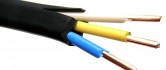
If the electrical wiring is done from scratch, then you should not run a separate cable for the grounding loop - it can be included in the common conductor, as an additional conductor to the existing phase and neutral. This means that any cable in the apartment must be three-wire: “phase”, “zero” and “ground”.
A separate paragraph in the PUE is devoted to PE conductors or grounding wires.
And paragraph 1.7.121. clearly states that:
- The ground wire can be laid together with the phase conductor.
- It is possible to use both insulated and non-insulated PE conductor.
Third subparagraph 1.7.121
. states that the grounding conductor can be laid permanently, as many electrical installation companies now do, which is quite justified.
What is grounding used for and how does it work?
Any electrician, even a freshman, will tell you that grounding is a specially created connection of working electrical equipment (a point or a network node) with some grounding device.
Ground bus.
The latter can be either specially mounted structures and devices, or soil. Both are equally effective, but are used in different cases.
The grounding device and working cables are selected depending on the purpose of the grounding. There are only a couple of main types:
- working (or functional),
- protective.
A process is called functional when it is directly necessary for the correct and proper operation of the equipment.
Protective, in turn, is grounding, which leads to safe operation of devices for humans. This type is not used directly all the time (unlike the previous one), but only in situations of breakdowns, failure or when the device is struck by lightning.
Note that protective grounding is often used to reduce the amount of electromagnetic interference.
In apartments and houses, protective grounding is carried out. For domestic purposes, an inexpensive grounding conductor is usually used - a single-core cable or part of a multi-core cable. The main component of the wire is always copper, but the cross-section varies. The main question that worries home craftsmen and inexperienced electricians is what cross-section should the grounding wire be? Let's try to answer.
Circuit design
Components
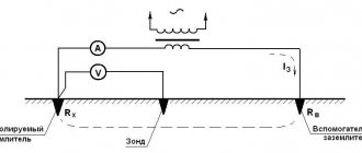
Ground loop
The previously mentioned grounding resistance (Rз) of the circuit is the main parameter controlled at all stages of its operation and determines the effectiveness of its use. This value must be so small as to provide a free path for the emergency current tending to flow into the ground.
Note! The most important factor that has a decisive influence on the value of grounding resistance is the quality and condition of the soil at the site of the installation.
Based on this, the charger in question or the ground loop of the charge circuit (which in our case is the same thing) must have a design that meets the following requirements:
- It must include a set of metal rods or pins with a length of at least 2 meters and a diameter of 10 to 25 millimeters;
- They are connected to each other (necessarily for welding) by plates of the same metal into a structure of a certain shape, forming a so-called “grounding conductor”;
- In addition, the device includes a supply copper busbar (also called electrical) with a cross-section determined by the type of equipment being protected and the magnitude of the drain current (see the table in the figure below).
Tire Section Table
Additional Information. Conventionally, this design includes connecting copper wires in the form of a bundle or braid.
These component devices are necessary to connect the elements of the protected equipment with the descent (copper busbar).
Differences in device location
According to the provisions of the PUE, the protective circuit can have both external and internal design, and each of them is subject to special requirements. The latter establishes not only the permissible resistance of the ground loop, but also stipulates the conditions for measuring this parameter in each particular case (outside and inside the object).
When dividing grounding systems according to their location, it should be remembered that only for external structures the question of how the grounding resistance is normalized is correct, since it is usually absent indoors. Internal structures are characterized by wiring of electrical busbars along the entire perimeter of the premises, to which grounded parts of equipment and devices are connected through flexible copper conductors.
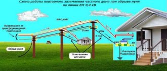
For structural elements grounded outside the facility, the concept of re-grounding resistance is introduced, which appeared as a result of the special organization of protection at the substation. The fact is that when forming a neutral protective conductor or a working conductor combined with it at the supply station, the neutral point of the equipment (step-down transformer, in particular) is already grounded once.
Therefore, when another local grounding is made at the opposite end of the same wire (usually a PEN or PE bus connected directly to the consumer panel), it can rightfully be called repeated. The organization of this type of protection is shown in the figure below.
Re-grounding
Important! The presence of local or repeated grounding allows you to insure yourself in case of damage to the protective neutral wire PEN (PE - in the TN-CS power supply system).
Such a malfunction is usually found in technical literature under the name “zero burnout.”
1.7.121
As PE
-conductors in electrical installations with voltage up to 1 kV can be used:
1) specially provided conductors:
cores of multi-core cables;
insulated or non-insulated wires in a common sheath with phase wires;
permanently laid insulated or non-insulated conductors;
2) open conductive parts of electrical installations:
aluminum cable sheaths;
steel pipes for electrical wiring;
metal shells and supporting structures of busbars and complete prefabricated devices.
Metal boxes and trays of electrical wiring can be used as protective conductors, provided that the design of the boxes and trays provides for such use, as indicated in the manufacturer's documentation, and their location excludes the possibility of mechanical damage;
3) some third party conductive parts:
metal building structures of buildings and structures (trusses, columns, etc.);
reinforcement of reinforced concrete building structures of buildings, subject to the requirements of 1.7.122;
metal structures for industrial purposes (crane rails, galleries, platforms, elevator shafts, lifts, elevators, channel frames, etc.).
Calculation example
Calculation of grounding of electrical equipment. Example - a private house, a single-phase electrical network is used, the required spreading resistance is not higher than 4 Ohms. Location: black earth soil: equivalent soil resistivity is 50 Ohm m. Steel pipes 160 cm long and 32 mm in diameter are used to equip the grounding system.
Calculation of one ground electrode:
Knowing the spreading resistance of one ground electrode, it is easy to calculate the required number:
Answer: 11 ground electrodes.
We select a cable for grounding.
Before selecting a ground wire, there are several other fundamental issues to consider.
Owners of private houses or country cottages, as well as old apartments built before 1998, have to carry out grounding themselves. Modern houses already have a ready-made grounding system, unlike all old ones. To select the correct section, you need to find out what system exists in the house.
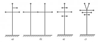
There are only four main ones, according to the Electrical Installation Rules (hereinafter PUE):
- TN-S - grounding is carried out using a separate wire and neutral in an alternating current system;
- TN-C - the “zero” and “ground” cables are combined into one wire, the neutral is separate, most common in houses of the last century;
- TT - direct protective grounding installed on electrical equipment;
- IT - working with the device body through resistance or complete insulation of all current-carrying cables.
Directly on the grounding diagram you should find one of the markings:
- PE - “grounding”,
- PEN - “zero” and “ground” in one cable.
The next important selection factor that will help determine the correct cross-section of the conductor is the type of grounding. Stationary or portable - depending on the purpose. For ordinary household grounding, a sufficient and stationary type, which in turn allows both multi-wire and single-wire multi-core cables.
The wire must be made in yellow-green insulation color, according to the PUE.
When we have decided on the type, material of the cable and the type of system, we move on to the main step - selecting the cable cross-section.
Issues covered in the PUE
Regulation of the operating procedure for various types of protective systems can be presented in the form of a certain set of requirements relating to the arrangement of individual structures.
According to them, the functional readiness of grounding loops, which include a whole set of structural elements, must be confirmed by the following technical data:
- Description of the design and composition of protective devices used in existing electrical installations;
- Formulas for calculating their sizes, as well as the resistance standards of grounding devices (GD);
- Tables with correction factors that allow you to introduce corrections for the quality and condition of the soil at the location of the contour (taking into account the material of individual elements);
- The procedure for organizing and conducting control tests available for grounding systems.
On a note. The presence of documented data on the performance characteristics and reliability of the functioning of the grounding loop of a private house, for example, will eliminate the possibility of electric shock to animals and residents.
When installing it, you are required to act in strict accordance with the PUE, as well as comply with all requirements regarding the operation of this protective device.
The principle of construction and purpose of protective grounding
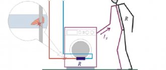
In simple terms, protective grounding is formed as follows. The ground wire is connected to a non-current-carrying metal part.
At the next stage, the “ground” connected to the equipment is combined, and then goes through a separate wire or busbar to the grounding device.
In the event of a voltage breakdown on a metal body and a person touches it, the potential goes through the ground and not through the body. Due to the low resistance, protection and RCDs operate faster.
In comparison, the R of a ground loop is only 4 ohms or less, and that of a human is more than 1000 ohms. According to Ohm's law, we know that current always follows the path of least resistance.
Thus, protective grounding is designed to solve the following problems:
- reducing the potential difference between the grounded device and other objects and protecting human life;
- draining current into the ground and increasing its values to trigger protective devices (RCDs, automatic devices).
Therefore, when laying a conductor for grounding, it is important to ensure the presence of protective devices. The latter must quickly respond to leakage or high currents by cutting off the damaged area. The sooner this happens, the better.
Design
Competent protective measures begin with a quality design. The project must take into account the peculiarities of the construction of the house and comply with regulatory documents. The best option is when grounding structures are laid at the time of the overall design of a house or cottage. Then you can use the internal elements of the structure as components of a protective grounding system - this will reduce the cost of grounding installation.
performs grounding calculations, design, assembly and maintenance of lightning protection and grounding loop elements, as an integral part of the system and a separate service.
Calculation of the cross-section of the grounding conductor
Many master electricians do not really delve into the essence of the issue and always purchase a cable with cores of the same cross-section. As a result, the “ground” wire does not differ from the phase or working “zero”. But the PUE provides for the smallest dimensions of grounding conductors and is listed in the form of formulas in a separate table.
Figure 2: Ground wires with pre-crimped terminal
Basic formulas for determining the smallest cross-section of a PE conductor:
- With phase cross-section S ≤ 16 mm2, cross-section of PE conductor: S.
- With phase cross-section 16 < S ≤ 35, cross-section of PE conductor: 16.
- With phase cross-section S > 35, cross-section of PE conductor: S/2.
It should be immediately clarified that such calculations are performed only at serious industrial enterprises, and when laying electrical wiring in scrap areas or apartments, they are very often neglected.
Adviсe
Dry soil is a poor conductor of electricity, so in sandy soils, the deeper the ground rods are driven, the better.
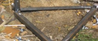
Being constantly in wet soil, a structure made of thin metal will very quickly collapse as a result of corrosion and will cease to perform its functions. Therefore, in wet soils, grounding rods must be made of sufficiently thick rolled materials.
In the photo: the grounding loop of the building is made of steel strip.
An aquifer well can serve as an excellent grounding if the casing pipe is made of metal.
If the roof of the house is made of metal tiles (corrugated sheets), it must be grounded. Such a design will be an excellent lightning protection for the building.
A ready-made lightning rod can be obtained by grounding the metal mast of a television antenna, if there is one.
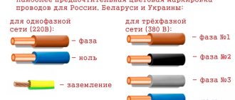
Ground wire color and connection features
To avoid confusion, it is important to understand what designations need to be provided for such wires.
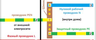
Today the following types of markings are used:
- PE - 0 protective wires and bars, colored in the form of intertwined yellow-green shades.
- N - 0th wires, indicated in blue (neutral).
- PEN - combination of zero and ground. The main part is blue, at the edges there is a combination of yellow and green colors.
In our case, a designation with the corresponding color design (yellow and green) is used. It is designated in the same way in a three-core wire.
If you don’t have a wire with the required color on hand, you can use regular yellow and green electrical tape. All that is required is to make marks on the ends of the wire.
Grounding (PE) is brought out and connected to the grounding bus, body or metal panel door. The neutral wire (N) is connected to the neutral busbar.
Read more about grounding and zeroing https://elektrikexpert.ru/zazemlenie-i-zanulenie.html, what is the difference between them.
Self-production
Making your own grounding is a sequential process consisting of several stages, each of which has its own characteristics. This does not require a pile of papers, since permission is not required in private construction. Installation should be carried out in the warm season, when the soil has thawed, dried out and settled.
To work you will need:
- welding machine;
- grinder, hammer drill;
- level, tape measure;
- pliers;
- shovel, sledgehammer;
- brush, paint;
- corrugated tube;
- aluminum tape.
The work is performed in the following sequence:
- Drawing up a project. Based on it, calculations of materials and equipment are carried out. You should make a small reserve, as errors are possible during the work process.
- Carrying out markings. The turf layer is carefully removed, then a pit of a given shape is torn off. The excavated material must be preserved, as it will be used for backfilling.
- From the middle of one side or from the corner, a flat trench is dug towards the building. It is needed for laying a cable or other current conductor between the frame and the electrical panel.
- The electrodes are cut out. Their ends are pointed for easier immersion into the soil. After this, the pins are driven into the ground at the corners of the trench. If a corner is used, holes are pre-drilled and the openings are filled with a mixture of earth and salt.
- The sides of the contour are cut out. They are connected to the electrodes and to each other. Welding areas are painted over.
- Near the ditch to the house, a bolt is welded to the frame. The cable is screwed to it. The joint is closed with a plastic bottle, the neck of which is sealed with aluminum tape.
- Entry into the house is made in the basement. To prevent chafing of the cable insulation, a flexible steel tube is inserted into the hole. The cable is pulled into it and connected to the shield.
- The final stage is filling the ditches with soil, leveling it and compacting it.
Main brands of grounding wires.
Grounding cable.
NYM cable
The conductors, or rather their shell, are painted in accordance with PUE standards, and there are copper conductors inside. It has an additional intermediate sheath, which increases the level of safety even with long-term use of the cable. Easy to use and install, suitable for voltages up to 660 Volts with a frequency of 50 hertz.
VVg cable
Cores with copper wire of the first and second class of twist have a characteristic color, with “zero” being blue and “ground” being yellow-green. The insulation and outer sheath are made of polyvinyl chloride, due to which the cable itself prevents combustion.
Wire PV-6
Copper, stranded, sheathed in transparent PVC. The conductor is clearly visible under such a sheath, making it easy to monitor the integrity of the entire length of the wire. Very flexible, can be easily exposed to temperatures ranging from -40 to +55 degrees Celsius.
Wire ESUY
Typical application is for system short circuit protection. Withstands enormous loads, found in work on railways and in distribution blocks. Resistant to temperatures and bending, has protection from physical and chemical influences.
Wire PV-3
Many thin soft strands of copper wire are woven under a single layer of polyvinyl chloride. The release is possible in eleven colors, but the yellow-green version is traditionally used for grounding.
A special feature of the shell is increased fragility under improper production or storage conditions. Pay attention to the fresh cut: there should be no breaks. Otherwise, it is not recommended to use the cable.
How to use all this? For grounding an ordinary average apartment, both multi-core VVG and single-wire NYM are equally suitable. Sometimes, in order to save money, PPV wire is used, without a characteristic color. This is fraught with problems when repairing or replacing wiring in the apartment. Often German ESUY, flexible single-core wires, are used for apartments.
As you can see, understanding which wire is needed for grounding is a rather difficult task, but doable. It is enough to carefully understand the issue and familiarize yourself with several provisions from the rules for electrical installations.
Marking
For a better understanding, let us raise the issue of marking the insulation of the conductors used.
The following symbols can be used in the wire name:
- A - aluminum core (in the absence of a letter - copper);
- AC - presence of lead braid;
- AA - stranded wire with an aluminum core and a braid of the same material;
- B - corrosion protection, made of double-layer steel;
- G - without shell;
- Bn - protection from moisture and resistance to fire;
- NP - non-flammable material;
- R - rubber shell;
- B - polyvinyl chloride shell;
- K - control cable, etc.
You must pay attention to the above markings when choosing a wire for grounding in relation to its cross-section (this was mentioned above).
Types
Grounding of buildings and electrical installations of various voltages is constructed according to one of three types: ring, deep or foundation. The choice of the type of circuit and materials for the ground electrode for a particular building is made taking into account its size and purpose, installation capabilities and limitations, the degree of saturation with electrical equipment and a number of other reasons. If necessary, several grounding systems can be interconnected (taking into account the risk of corrosion). Any building grounding must be connected to a potential equalization bus.
Photo of wires for grounding
Did you like the article? Share