A button is the simplest device with which you can control the progress of a program on a microcontroller, but physically it performs a very simple function: it closes and opens a contact. There are several types of buttons:
- With latching – the button remains pressed after being released, without latching – it turns back off.
- Normally Open (NO) – when pressed, it closes the contacts. Normally Closed (NC) – when pressed, opens the contacts.
- Tact buttons - close or open a contact. For conventional tact buttons, the legs are connected lengthwise through the body (see picture below). Switches - usually have three contacts, common COM , normally open NO and normally closed NC . When the button is released, the COM-NC ; when pressed, the COM-NO .
Connection and tightening
From the lesson about digital pins, you remember that the microcontroller can read the voltage from its leg. Accordingly, the button can apply to the pin the level to which its second leg is connected. In the same lesson, we discussed that a digital pin that is not connected anywhere receives interference from the air, and the value read from it will be almost random. That is, by connecting a 5V (high-level signal) to the pin via a button, we will not achieve anything: when the button is pressed, a clear high-level signal will be read on the pin, and when released, a random value will be read. To solve this problem, there is such a thing as pin pull. The pull-up is performed to ground (pull down) or power supply (pull up) of the microcontroller using a resistor. The pull-up is performed opposite to the received signal, i.e. if you need to catch a high signal, the pull-up is performed to the ground; if you need to catch a ground signal, the pull-up is performed to the power supply. Here are two options for connecting the button, with pull-up to VCC and GND, respectively:
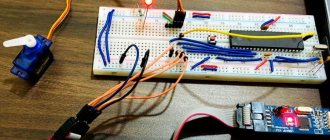
How is the resistor value selected? Everything is very simple here: when you press the button, current will flow through the resistor, since in any case the power-ground circuit is closed. The higher the current, the greater the energy loss and heating of the resistor, and no one needs this, so the resistance of the pull-up resistor is usually selected in the range of 5-50 kOhm. If you set it more, the pull-up may not provide a stable signal level on the pin, and if you set it less, there will be more energy loss in heating the resistor: with a resistance of 1 kohm, a current of 5 V/1000 Ohm = 5 mA will flow through it, for comparison, the Arduino board with MK in active mode it consumes 20-22 mA. Most often, a 10 kOhm resistor is used for pull-up. As you remember from the lesson about digital pins, the AVR MK has built-in resistors for all GPIOs, these resistors are connected to the power (to VCC ), that is, they literally duplicate the first circuit from this lesson and allow you not to use an external resistor. Microcontrollers of other architectures may have a pull-up to GND, or may not have an internal pull-up at all. When using a power pull-up, we will receive an inverted signal - the digitalRead() function will return 1 when the button is released, and 0 when pressed (when using a normally open button). Let's connect the button to pin D3 (and GND):
void setup() { Serial.begin(9600); pinMode(3, INPUT_PULLUP); } void loop() { // will print 0 if the button is pressed // and 1 if not Serial.println(digitalRead(3)); delay(10); }
Trigger button program
Another example worth noting is the trigger button. It works like this: press the button once - the LED lights up, press it a second time - it goes out.
To implement this button behavior, we need an additional variable, often called a “state variable” or “flag”.
const int led = 2; const int button = 3; int val = 0; byte state = 0; // state variable void setup(){ pinMode( led, OUTPUT ); pinMode( button, INPUT ); } void loop(){ // write the state of the button to the variable val val = digitalRead( button ); // if the button state is true, perform the action if( val == HIGH ){ // change the state to the opposite state = !state; if( state == HIGH ){ // if the current state is true, light the LED digitalWrite( led, HIGH ); } else { // if the current state is false, turn off the LED digitalWrite( led, LOW ); } delay( 300 ); } }
We load the program onto Arduino and check the operation of the circuit. Quickly press the button and the LED will light up. Press again and it will go out. But if you press the button and do not release it, the LED will start blinking with a period of 600ms! Why is that? Try to figure it out.
Algorithms
Practicing pressing
In most real-life applications, working with the current state of a button is very inconvenient, for example when the action must be performed once when the button is pressed, i.e. on click. Let's complicate the design a little by adding one flag that will remember the state of the button. This design allows you to track the pressing and releasing of a button and respond to them once:
void setup() { Serial.begin(9600); pinMode(3, INPUT_PULLUP); } bool flag = false; void loop() { // read the inverted value for convenience bool btnState = !digitalRead(3); if (btnState && !flag) { // click handler flag = true; Serial.println("press"); } if (!btnState && flag) { // release handler flag = false; //Serial.println("release"); } }
Contact bounce
The button is not ideal, and the contact does not close immediately; it “rattles” for some time. Running this algorithm, the system polls the button and conditions in approximately 6 μs, that is, the button is polled 166,666 times per second! This is enough to get several thousand false positives.
You can get rid of contact bounce both in hardware and in software: in hardware, the problem is solved using an RC circuit, that is, a resistor (~1-10k) and a capacitor (~100nF). It looks like this:
Programmatically, you can enter a simple click timer based on millis(); let’s take the debouncing time to be 100 milliseconds. This is what the code will look like:
void setup() { Serial.begin(9600); pinMode(3, INPUT_PULLUP); } bool flag = false; uint32_t btnTimer = 0; void loop() { // read the inverted value for convenience bool btnState = !digitalRead(3); if (btnState && !flag && millis() - btnTimer > 100) { flag = true; btnTimer = millis(); Serial.println("press"); } if (!btnState && flag && millis() - btnTimer > 100) { flag = false; btnTimer = millis(); //Serial.println("release"); } }
It is, of course, recommended to use the hardware method, since it does not load the kernel with unnecessary calculations. In 99.99% of projects, software anti-debounce will be sufficient, so feel free to use the construction with millis().
“Pulse” hold
In devices with button control, it is very often necessary to be able to change the value either by clicking the button once, or “automatically” with the same step - by holding it down. This option is implemented very simply by adding one more condition to our previous algorithm, namely: if the button was pressed but not yet released, and more time has passed than the specified one, the condition will return true. In the example below, the frequency of “clicks” while holding is set to 500 milliseconds (2 times per second):
void setup() { Serial.begin(9600); pinMode(3, INPUT_PULLUP); } bool flag = false; uint32_t btnTimer = 0; void loop() { // read the inverted value for convenience bool btnState = !digitalRead(3); if (btnState && !flag && millis() - btnTimer > 100) { flag = true; btnTimer = millis(); Serial.println("press"); } if (btnState && flag && millis() - btnTimer > 500) { btnTimer = millis(); Serial.println("press hold"); } if (!btnState && flag && millis() - btnTimer > 500) { flag = false; btnTimer = millis(); //Serial.println("release"); } }
It will be inconvenient to use such code directly, so you can “wrap” it in a class (read the lesson about classes and the lesson about writing libraries).
The simplest button class
This is how the previous example can be made into a class (we did it in this lesson), put it in a separate file (button.h) and use it:
button.h
class button { public: button (byte pin) { _pin = pin; pinMode(_pin, INPUT_PULLUP); } bool click() { bool btnState = digitalRead(_pin); if (!btnState && !_flag && millis() - _tmr >= 100) { _flag = true; _tmr = millis(); return true; } if (!btnState && _flag && millis() - _tmr >= 500) { _tmr = millis(); return true; } if (btnState && _flag) { _flag = false; _tmr = millis(); } return false; } private: byte_pin; uint32_t_tmr; bool_flag; };
And an example with this “library”: // the file is in the same folder with the sketch #include “button.h” button btn1(3); // specify the pin button btn2(4); void setup() { Serial.begin(9600); } void loop() { // the click() method “fires” once when you click // and pulses when you hold it if (btn1.click()) Serial.println(“press 1”); if (btn2.click()) Serial.println("press 2"); }
Other button options
The button only in appearance seems to be a simple device that gives 0 and 1, but with imagination and time, you can come up with many more uses for a regular button. My GyverButton library implements a lot of interesting features for working with a button, here is the list:
- Working with normally closed and normally open buttons
- Working with PULL_UP and PULL_DOWN Polling a button with software contact anti-bouncing (adjustable time)
- Practicing pressing, holding, releasing, clicking a button (+ setting timeouts)
- Practicing single, double and triple clicks (taken separately)
- Processing any number of button presses (the function returns the number of presses)
- Function for changing the value of a variable with a given step and a given time interval
- Ability to work with “virtual” buttons (all library features are used for matrix and resistive keyboards)
A detailed description of the library can be read in the header file on the library page; there are also many examples there.
How do switches differ in design and installation method?
In addition to functionality, electrical switches vary in design and installation method. This affects the complexity of installation and location of operation.
External switches
Such switches are located on the surface of the wall. The wiring can be external (most often) or internal. Installation is simple as there is no need to drill a hole for the switch boxes. Used where it is not possible to deepen the switch housing or as a temporary switch.
Outdoor switch.
Built-in switches
A large hole is made in the wall for installation. The switch body is inserted into the formed cavity so that it is flush with the surface or protrudes slightly above it. This provides a neater appearance and it is impossible for clothes to accidentally get caught on such a switch. However, such an installation requires hidden installation of wiring and preparation of holes for boxes in which switches are installed.
Built-in switch.
Sealed switches
Such devices are protected from moisture and dust. Depending on the degree of protection, they are designated by the letters IP with specific meanings. Such switches are intended for installation in rooms with high levels of moisture, dust, liquid splashes, etc. They ensure safety by reliably isolating contacts from water penetration. For installation in bathrooms, the protection class of the switch must be at least IP-44.
If you notice an error, a non-working video or link, please select a piece of text and press Ctrl+Enter .
0
Important Pages
- GyverKIT kit - a large Arduino starter kit of my design, sold in Russia
- Catalog of links to cheap Arduins, sensors, modules and other hardware from AliExpress from trusted sellers
- A selection of libraries for Arduino, the most interesting and useful, official and not so
- Complete documentation on the Arduino language, all built-in functions and macros, all available data types
- A collection of useful algorithms for writing sketches: code structure, timers, filters, data parsing
- Video lessons on Arduino programming from the “Arduino Engineer's Notes ” channel are some of the most detailed in RuNet
- Support the author for his work on the lessons
- Feedback - report an error in the lesson or suggest an addition to the text ( [email protected] )
5 / 5 ( 12 votes)
Operating principle
The principle of operation of a switch
To understand what a switch is, you need to consider the principle of its operation and purpose. The device serves to redirect the flow of electricity to another circuit - one circuit is disconnected and the other is closed at the same time. Therefore, the minimum number of contacts for such a device is three. For mechanisms with two or more “keys” the number doubles.
A switch is a switch between electrical conductors of reverse voltage. Purpose – control of one light source from different places. Mainly used for premises with a large area, for example, stadiums, production workshops or warehouses.