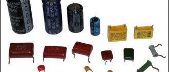
Capacitor radio components contain plates of an electrically conductive substance separated by a dielectric layer. They differ from other devices used in electrical circuits in their ability to accumulate electrical charge. To correctly select the appropriate part, you need to have an idea of what the unit of measurement that describes the capacitance of the capacitor is and be able to read the symbols on the markings.
Capacitive radio components
Other measurement methods
Maximum data accuracy can be achieved by using an immittance indicator.
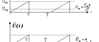
The problem is that such devices require large budget investments, often costing more than 100 thousand rubles. Another way is to assemble a circuit from a resistor and a capacitor. First, the resistance of the first is measured, and the voltage of the power source is also measured. Having assembled the circuit, the capacitive element is short-circuited, the circuit is connected to power, the voltage is measured and multiplied by 0.95. After unwinding, measure the time during which the voltage drops from 100 to 95%. This figure must be divided by triple the resistor value. This will be the capacitance indicator in farads.
The unit farad is used to describe the capacitance values of both capacitor devices and conductors. To select the correct parts, you must be able to decipher the markings on the body.
How to measure capacitance of a capacitor with a multimeter
To perform such an operation, you need a device with a capacitance measurement mode (often marked as C or Cx). It must have a resistance greater than 2 kilo-ohms. Before measurements, it is necessary to discharge the contacts of the device. A screwdriver with a handle coated with an insulating material (for example, rubberized) is suitable for this. You need to take the tool by the handle and touch the contacts, after which they will close. Then you need to keep the capacitor de-energized for about half an hour so that it is completely discharged.
Important! If the capacitive radio component malfunctions, the measuring device will show an infinite value and begin to make beeping sounds. Devices that have punctures or bulges on the housing cannot be tested - such capacitors are unsuitable for use.
The electrical circuit is disconnected from power. After this, you need to make sure that it is absent by placing the probes on the supplier with a preset voltage measurement program. The parameter must have a zero value.
The measuring device is placed in the capacitance parameter measurement mode. When using a device with several setting intervals, choose the one that is most likely to fit (based on the marking data). If there is a Rel button, it is used to release the probes from the capacitive load. The probes are placed to the terminals of the part, strictly observing the polarization. If, after waiting, the screen reports overload, the capacity is too large for this device to identify, or a different interval must be selected.
Multimeter measurement
Application of capacitors
This category of elements is very widely used in all areas of electronics and a number of other industries. Among the main areas of application are:
- television and sound reproducing equipment;
- radar devices (here capacitors help generate pulses and increase their power);
- telephone and telegraph devices - in them devices are used to separate types of circuits (by frequency, variability-constancy) and extinguish sparks in contacts;
- measuring electronic instruments;
- lasers (increasing pulse power);
- overvoltage protection in electrical power plants;
- electric welding work using a discharge;
- blocking machine-generated radio interference;
- starting electric motors and creating a phase shift in the additional winding;
- generators used during electrical testing to produce current and voltage pulses.
Capacitor element dimensions
Farad
Capacitor elements are used in a very wide range of areas - from printed circuit boards (miniature SMD components) to powerful motors and pulse generators. To correctly select a capacitor, you need to be able to decipher the markings and symbols on the diagrams, in particular, navigate the symbols of device capacitance.
Calculation using formulas
Calculation of the nominal capacity of an element is required in 2 cases:
- Electronic equipment designers calculate the parameter when creating circuits.
- In the absence of capacitors of suitable power and capacity, craftsmen use element calculations to select from available parts.
RC circuits are calculated using the value of impedance - complex resistance (Z). Ra - current losses due to heating of circuit participants. Ri and Re — take into account the influence of inductance and capacitance of the elements. At the resistor terminals in the RC circuit, the voltage Uр is inversely proportional to Z.
Marking of capacitors depending on capacity
When purchasing elements that correspond to the calculated data for a particular circuit, the user needs to be able to decipher the symbols on the device cases, informing how much capacity they are capable of accumulating. Different manufacturers have adopted different marking systems for radio components.
Encoding of small devices
On the housings of Soviet radio components, it was customary to designate picofarads as an integer (for example, 25). If on such a part the parameter is indicated by a number containing a decimal fraction, microfarads are implied. It was not customary to write the letter designations themselves (pF, μF and the like) on the housings.
Important! As for Russian products, nanofarads and microfarads are indicated by traditional abbreviations in which the letter F is reduced (it turns out “n” and “mk”, respectively). Capacity, calculated in picofarads, is indicated only by number, as with Soviet parts
When a Latin prefix indicating a multiple of one is placed before a number, the latter must be counted as hundredths. For example, n45 means 0.45 nanofarads. When the prefix is in the middle of a number, there should be a comma in its place: 4u3 – 4.3 microfarads. A three-digit picofarad encoding is also used: when the last digit is not more than 6, in order to obtain a capacitive value, the first two digits must be assigned the number of zeros corresponding to this digit (340 - 34 picofarads, 342 - 3400). The numbers 7, 8 and 9 correspond to multiplications of a two-digit number by 0.001, 0.01 and 0.1, respectively.
Colored stripes are also used to designate product denominations. The indication of the capacitive parameter is regulated by the EIA standard.
Encoding of large devices
For large components, for example electrolytic ones made of aluminum, parameter data, including capacitance indicator, is indicated on the surface of the housing. Typically, the capacitance of such parts is expressed in microfarads. The letters M or MFD symbolize this particular unit. The three-digit abbreviation can also be indicated in lowercase letters - mfd.
Marking of large parts
Abbreviated notation of numerical quantities
Radio electronics for beginners
- When assembling electronic circuits, willy-nilly you have to recalculate the resistance values of resistors, capacitor capacities, and inductance of coils.
- So, for example, there is a need to convert microfarads into picofarads, kilo-ohms into ohms, millihenry into microhenry.
- How not to get confused in calculations?
- If a mistake is made and an element with the wrong rating is selected, the assembled device will not work correctly or have other characteristics.
This situation is not uncommon in practice, since sometimes on the housings of radio elements the capacitance value is indicated in nanofarads (nF), and on the circuit diagram the capacitance of capacitors is usually indicated in microfarads (uF) and pico farads (pF). This misleads many novice radio amateurs and, as a result, slows down the assembly of the electronic device.
To prevent this situation from happening, you need to learn simple calculations.
In order not to get confused in microfarads, nanofarads, picofarads, you need to familiarize yourself with the dimension table. I'm sure you will find it useful more than once.
This table includes decimal multiples and fractional (multiple) prefixes. The international system of units, which is abbreviated as SI , includes six multiples (deca, hecto, kilo, mega, giga, tera) and eight submultiple prefixes (deci, centi, milli, micro, nano, pico, femto, atto). Many of these attachments have been used in electronics for a long time.
| Factor | Console | ||
| Name | Abbreviation | ||
| Russian | international | ||
| 1000 000 000 000 = 1012 | Tera | T | T |
| 1000 000 000 = 109 | Giga | G | G |
| 1000 000 = 106 | Mega | M | M |
| 1000 = 103 | kilo | To | k |
| 100 = 102 | Hecto | G | h |
| 10 = 101 | soundboard | Yes | da |
| 0,1 = 10-1 | deci | d | d |
| 0,01 = 10-2 | centi | With | c |
| 0,001 = 10-3 | Milli | m | m |
| 0,000 001 = 10-6 | micro | mk | μ |
| 0,000 000 001 = 10-9 | nano | n | n |
| 0,000 000 000 001 = 10-12 | pico | P | p |
| 0,000 000 000 000 001 = 10-15 | femto | f | f |
| 0,000 000 000 000 000 001 = 10-18 | atto | A | a |
How to use the table?
As we can see from the table, the difference between many prefixes is exactly 1000. So, for example, this rule applies between multiples, starting with the prefix kilo- .
- Kilo - 1000
- Mega - 1,000,000
- Giga – 1,000,000,000
- Tera – 1,000,000,000,000
Mega is written next to the resistor designation , then its resistance will be 1,000,000 (1 million) Ohm. If there is a resistor with a nominal resistance of 1 kOhm (1 kilo ohm), then in Ohms it will be 1000 (1 thousand) Ohms.
For submultiple or otherwise fractional values, the situation is similar, only the numerical value does not increase, but decreases.
In order not to get confused in microfarads, nanofarads, picofarads, you need to remember one simple rule. You need to understand that milli, micro, nano and pico - they all differ by exactly 1000 .
That is, if they tell you 47 microfarads, then this means that in nanofarads it will be 1000 times more - 47,000 nanofarads. In picofarads this will already be another 1000 times more - 47,000,000 picofarads.
As you can see, the difference between 1 microfarad and 1 picofarad is 1,000,000 times.
Also in practice, sometimes it is necessary to know the value in microfarads, but the value of the capacitance is indicated in nanofarads. So if the capacitance of the capacitor is 1 nanofarad, then in microfarads it will be 0.001 microfarads. If the capacitance is 0.01 microfarads, then in picofarads it will be 10,000 pF, and in nanofarads, respectively, 10 nF.
Prefixes denoting the dimension of a quantity are used for abbreviated notation. Agree, it’s easier to write 1mA than 0.001 Ampere or, for example, 400 µH than 0.0004 Henry.
The table shown earlier also contains an abbreviated designation for the prefix. So, in order not to write Mega , they write only the letter M. The prefix is usually followed by an abbreviation for the electrical quantity.
For example, the word Ampere is not written, but only the letter A . The same is done when abbreviating the unit of measurement of capacitance Farad . In this case, only the letter F .
Along with the abbreviated notation in Russian, which is often used in old radio-electronic literature, there is also an international abbreviated notation of prefixes. It is also indicated in the table.
Multiples and submultiples
Most often in electronics, elements with small capacitances are used, which is why those starting to work with circuits have questions: pF is how many farads, 100 nf is how many microfarads, and so on. In this regard, you should have with you a table of conversion of one unit to another. The most commonly used submultiple units include:
How to choose and calculate the capacitance of a capacitor for a three-phase motor
- microfarad (μF) – 0.000001 F;
- nanofarad (nF) – 0.000000001 F;
- picofarad (pF) – 0.000000000001 F.
Of the multiple units, the kilofarad (kF) is used, equal to a thousand farads. Such indicators are typical for ionistors. For conventional capacitors, the capacitance is usually measured in a maximum of tens of farads.
In the Soviet Union, there was a tendency on electrical circuits and capacitor housings to indicate the capacitance value as a whole number (for example, 35). To mean picofarads, and a fraction with one digit after the decimal point meant microfarads. Letters were not used in such container markings. On modern domestic capacitors, when indicating the capacitance in picofarads, the measuring units are usually not written after the number. If the letters “mk” are indicated, microfarads are implied, if “n” - nanofarads are implied. Abroad they use markings made of colored stripes.
Table for converting some fractional capacitance units to others
Color coding of ceramic capacitors.
Colored stripes are applied on the capacitor body, from left to right, or from top to bottom. As a rule, the capacity value is encoded by the first three stripes. Each color in the first two stripes has its own number: black - number 0; brown - 1; red - 2; orange - 3; yellow - 4; green - 5; blue - 6; purple - 7; gray - 8; white - 9. Thus, if, for example, the first stripe is brown and the second is yellow, then this corresponds to the number -14. But this number will not be the value of the nominal capacitance of the capacitor; it still needs to be multiplied by the multiplier encoded by the third stripe.
In the third stripe, the colors have the following meanings: orange - 1000; yellow - 10000; green - 100000. Let's assume that the color of the third strip of our capacitor is yellow. We multiply 14 by 10000, we get the capacity in picofarads -140000, otherwise, 140 nanofarads or 0.14 microfarads. The fourth strip indicates permissible deviations from the nominal capacity (accuracy), as a percentage: white - ± 10%; black - ± 20%. The fifth bar is the rated operating voltage. Red color - 250 Volts, yellow - 400.
Multiples of capacity units
In most cases in electrical engineering, parts with small capacitance values are operated. Sometimes you will see designations such as 10uf capacitor. An inexperienced person may not immediately understand what the abbreviation uf means. It should be understood that the most common units in the description of capacitive elements are the following units: picofarad (or pF, it is equal to 10-12 F), nanofarad (nF, 10-9 F) and microfarad (μF, 10-6 F). Specifying the capacitance of a capacitor in uf means microfarads. It is advisable to purchase a table for converting measurement units of different scales to each other.
Multiple units are not used that often in practice. For some ionistor parts with a binary electrical layer, the capacitance indicator can be measured in kilofarads (kF, 1000 F). The value of standard capacitor elements usually does not exceed hundreds of farads.
Ionistor with a nominal value of 1 farad
General information
Measuring the capacitance of a capacitor with a nominal capacitance of 10 µF using an oscilloscope-multimeter
Electric capacitance is a quantity characterizing the ability of a conductor to accumulate charge, equal to the ratio of the electric charge to the potential difference between the conductors:
C = Q/∆φ
Electric field
Here Q
- electric charge, measured in coulombs (C), - potential difference, measured in volts (V).
In the SI system, electrical capacitance is measured in farads (F). This unit of measurement is named after the English physicist Michael Faraday.
A farad is a very large capacitance for an insulated conductor. Thus, a solitary metal ball with a radius of 13 solar radii would have a capacity equal to 1 farad. And the capacitance of a metal ball the size of Earth would be approximately 710 microfarads (µF).
Since 1 farad is a very large capacitance, smaller values are used, such as: microfarad (μF), equal to one millionth of a farad; nanofarad (nF), equal to one billionth; picofarad (pF), equal to one trillionth of a farad.
In the SGSE system, the basic unit of capacity is the centimeter (cm). 1 centimeter of capacity is the electrical capacity of a ball with a radius of 1 centimeter placed in a vacuum. GSSE is an extended GSSE system for electrodynamics, that is, a system of units in which the centimeter, gram, and second are taken as the base units for calculating length, mass, and time, respectively. In extended GHS, including SGSE, some physical constants are taken to be unity to simplify formulas and facilitate calculations.
Farads through SI base units
Voltage unit
To express the unit in question in terms of others, you can start from the capacity formula:
C = q/U, where q is the charge (usually calculated in coulombs), and U is the potential difference between the plates (measured in volts).
It turns out that F=Cl/V. The following expression is also true:
F = (c4*A2)/(kg*m2).
Here we mean from left to right: second, ampere, kilogram and square meter.
Application area
Farads measure the electrical capacitance of conductors, that is, their ability to accumulate electrical charge. For example, in farads (and derivative units) the following is measured: the capacitance of cables, capacitors, interelectrode capacitances of various devices. Industrial capacitors have ratings measured in micro-
,
nano-
and
picofarads
and are available in capacities up to one hundred farads; Audio equipment uses hybrid capacitors with a capacity of up to forty farads.
Do not confuse the electrical capacity and the electrochemical capacity of batteries and accumulators, which has a different nature and is measured in other units: ampere-hours, commensurate with the electric charge (1 ampere-hour is equal to 3600 coulombs).
Video
A capacitor is an electronic component designed to store electrical charge. The ability of a capacitor to accumulate electrical charge depends on its main characteristic - capacitance . The capacitance of a capacitor (C) is defined as the ratio of the amount of electrical charge (Q) to voltage (U).
The capacitance of a capacitor is measured in farads (F), a unit named after the British physicist Michael Faraday. A capacitance of one farad (1F) is equal to the amount of charge of one coulomb (1C) creating a voltage across the capacitor of one volt (1V). Recall that one coulomb (1C) is equal to the amount of charge passing through the conductor in one second (1sec) with a current of one ampere (1A).
However, a pendant is a very large amount of charge relative to how much charge most capacitors can store. For this reason, microfarads (µF or uF), nanofarads (nF) and picofarads (pF) are commonly used to measure capacitance.
- 1µF = 0.000001 = 10 -6 F
- 1nF = 0.000000001 = 10 -9 F
- 1pF = 0.000000000001 = 10 -12 F
Device characteristics
The most important characteristic of a storage device is capacity. The charging time depends on it when the device is connected to a power source. The discharge time is directly related to the value of the load resistance: the higher it is, the faster the process of releasing the accumulated energy occurs. This capacity is determined by the following expression:
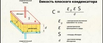
C = E*Eo*S / d, where E is the relative dielectric constant of the medium (reference value), S is the area of the plates, d is the distance between them. In addition to capacity, the capacitor is characterized by a number of parameters, such as:
- specific capacitance - determines the ratio of the capacitance to the mass of the dielectric;
- operating voltage - the nominal value that the device can withstand when applied to the plates of the element;
- temperature stability - the range in which the capacitance of the capacitor practically does not change;
- insulation resistance - characterized by the self-discharge of the device and determined by the leakage current;
- equivalent resistance - consists of losses generated at the terminals of the device and the dielectric layer;
- absorption - the process of the emergence of a potential difference on the plates after the device is discharged to zero;
- capacitance - a decrease in conductivity when alternating current is supplied;
- polarity - due to the physical properties of the material used in manufacturing, the capacitor can operate correctly only if a potential with a certain sign is applied to the plates;
- equivalent inductance is a parasitic parameter that appears on the contacts of the device and turns the capacitor into an oscillating circuit.
Tables of maximum capacitance values.
Parasitic parameters
Certain types of parameters are parasitic, which they try to reduce during design and manufacturing. Their description is given below.
Equivalent circuit
This parameter depends on the properties of the dielectric and the housing material. It shows how much the charge decreases over time for an element not included in an external circuit. Leakage occurs as a result of imperfection of the dielectric and along its surface.
For some capacitors, the characteristics indicate a time constant T, which shows the time during which the voltage on the plates will decrease by e (2.71) times. Numerically, the time constant is equal to the product of leakage resistance and capacitance.
Equivalent series resistance (Rs)
The equivalent series resistance of the ESR (in English literature ERS) is composed of the resistance of the material of the plates and leads. Surface dielectric leakage may also be added to this.
At its core, EPS is a resistance connected in series with an ideal capacitor. Such a circuit in some cases can affect the phase-frequency characteristics. ESR must be taken into account when designing switching power supplies and autoregulation circuits.
Electrolytic capacitors have a feature where, due to the presence of electrolyte vapor inside, affecting the terminals, the ESR value increases over time.
Equivalent series inductance (Li)
Since the terminals of the plates and the plates themselves are metal, they have some inductance. Thus, the capacitor is a resonant circuit, which can affect the operation of the circuit in a certain frequency range. SMD components have the lowest inductance due to their lack of wire leads.
Dielectric loss tangent
The ratio of active power transmitted through a capacitor to reactive power is called the dielectric loss tangent. This value depends on the losses in the dielectric and causes a phase shift between the voltage on the plate and the current. Loss tangent is important when operating at high frequencies.
Temperature coefficient of capacity (TKE)
TKE means the change in capacitance with temperature fluctuations. TKE can be either positive or negative, depending on how the capacitance behaves with temperature changes.
For filtering and resonant circuits, to compensate for temperature drift in one circuit, elements with different TKE are used, so many manufacturers group the elements produced by the value and sign of the coefficient.
Dielectric absorption
This effect is also called the memory effect. It manifests itself in the fact that when a capacitor is discharged through a low-resistance load, after some time a small voltage appears on the plates.
The amount of dielectric absorption depends on the materials from which the element is made. It is minimal for Teflon and polystyrene and maximum for tantalum capacitors
It is important to consider the effect when working with precision devices, especially integrating and differentiating circuits
Parasitic piezoelectric effect
The so-called “microphone effect” is expressed in the fact that when exposed to mechanical loads, including acoustic vibrations, the ceramic dielectric in some types of devices exhibits piezoelectric properties and begins to generate interference.
Self-healing
Electrolytic paper and film capacitors have the property of self-healing after electrical breakdown. These types of capacitors and their varieties have found application in circuits that provide starting of electric motors, especially if a three-phase asynchronous electric motor is connected to a single-phase network. The recovery property is widely used in strength engineering.
Conversion table for capacitances and capacitor designations
Table of capacitances and capacitor designations
| μF microfarads | nF nanofarads | pF picofarads | Code / Three-digit code |
| 1μF | 1000nF | 1000000pF | 105 |
| 0.82μF | 820nF | 820000pF | 824 |
| 0.8μF | 800nF | 800000pF | 804 |
| 0.7μF | 700nF | 700000pF | 704 |
| 0.68μF | 680nF | 680000pF | 624 |
| 0.6μF | 600nF | 600000pF | 604 |
| 0.56μF | 560nF | 560000pF | 564 |
| 0.5μF | 500nF | 500000pF | 504 |
| 0.47μF | 470nF | 470000pF | 474 |
| 0.4μF | 400nF | 400000pF | 404 |
| 0.39μF | 390nF | 390000pF | 394 |
| 0.33μF | 330nF | 330000pF | 334 |
| 0.3μF | 300nF | 300000pF | 304 |
| 0.27μF | 270nF | 270000pF | 274 |
| 0.25μF | 250nF | 250000pF | 254 |
| 0.22μF | 220nF | 220000pF | 224 |
| 0.2μF | 200nF | 200000pF | 204 |
| 0.18μF | 180nF | 180000pF | 184 |
| 0.15μF | 150nF | 150000pF | 154 |
| 0.12μF | 120nF | 120000pF | 124 |
| 0.1μF | 100nF | 100000pF | 104 |
| 0.082μF | 82nF | 82000pF | 823 |
| 0.08μF | 80nF | 80000pF | 803 |
| 0.07μF | 70nF | 70000pF | 703 |
| 0.068μF | 68nF | 68000pF | 683 |
| 0.06μF | 60nF | 60000pF | 603 |
| 0.056μF | 56nF | 56000pF | 563 |
| 0.05μF | 50nF | 50000pF | 503 |
| 0.047μF | 47nF | 47000pF | 473 |
| μF microfarads | nF nanofarads | pF picofarads | Code / Three-digit code |
| 0.04μF | 40nF | 40000pF | 403 |
| 0.039μF | 39nF | 39000pF | 393 |
| 0.033μF | 33nF | 33000pF | 333 |
| 0.03μF | 30nF | 30000pF | 303 |
| 0.027μF | 27nF | 27000pF | 273 |
| 0.025μF | 25nF | 25000pF | 253 |
| 0.022μF | 22nF | 22000pF | 223 |
| 0.02μF | 20nF | 20000pF | 203 |
| 0.018μF | 18nF | 18000pF | 183 |
| 0.015μF | 15nF | 15000pF | 153 |
| 0.012μF | 12nF | 12000pF | 123 |
| 0.01μF | 10nF | 10000pF | 103 |
| 0.0082μF | 8.2nF | 8200pF | 822 |
| 0.008μF | 8nF | 8000pF | 802 |
| 0.007μF | 7nF | 7000pF | 702 |
| 0.0068μF | 6.8nF | 6800pF | 682 |
| 0.006μF | 6nF | 6000pF | 602 |
| 0.0056μF | 5.6nF | 5600pF | 562 |
| 0.005μF | 5nF | 5000pF | 502 |
| 0.0047μF | 4.7nF | 4700pF | 472 |
| 0.004μF | 4nF | 4000pF | 402 |
| 0.0039μF | 3.9nF | 3900pF | 392 |
| 0.0033μF | 3.3nF | 3300pF | 332 |
| 0.003μF | 3nF | 3000pF | 302 |
| 0.0027μF | 2.7nF | 2700pF | 272 |
| 0.0025μF | 2.5nF | 2500pF | 252 |
| 0.0022μF | 2.2nF | 2200pF | 222 |
| 0.002μF | 2nF | 2000pF | 202 |
| 0.0018μF | 1.8nF | 1800pF | 182 |
| μF microfarads | nF nanofarads | pF picofarads | Code / Three-digit code |
| 0.0015μF | 1.5nF | 1500pF | 152 |
| 0.0012μF | 1.2nF | 1200pF | 122 |
| 0.001μF | 1nF | 1000pF | 102 |
| 0.00082μF | 0.82nF | 820pF | 821 |
| 0.0008μF | 0.8nF | 800pF | 801 |
| 0.0007μF | 0.7nF | 700pF | 701 |
| 0.00068μF | 0.68nF | 680pF | 681 |
| 0.0006μF | 0.6nF | 600pF | 621 |
| 0.00056μF | 0.56nF | 560pF | 561 |
| 0.0005μF | 0.5nF | 500pF | 52 |
| 0.00047μF | 0.47nF | 470pF | 471 |
| 0.0004μF | 0.4nF | 400pF | 401 |
| 0.00039μF | 0.39nF | 390pF | 391 |
| 0.00033μF | 0.33nF | 330pF | 331 |
| 0.0003μF | 0.3nF | 300pF | 301 |
| 0.00027μF | 0.27nF | 270pF | 271 |
| 0.00025μF | 0.25nF | 250pF | 251 |
| 0.00022μF | 0.22nF | 220pF | 221 |
| 0.0002μF | 0.2nF | 200pF | 201 |
| 0.00018μF | 0.18nF | 180pF | 181 |
| 0.00015μF | 0.15nF | 150pF | 151 |
| 0.00012μF | 0.12nF | 120pF | 121 |
| 0.0001μF | 0.1nF | 100pF | 101 |
| 0.000082μF | 0.082nF | 82pF | 820 |
| 0.00008μF | 0.08nF | 80pF | 800 |
| 0.00007μF | 0.07nF | 70pF | 700 |
| μF microfarads | nF nanofarads | pF picofarads | Code / Three-digit code |
| 0.000068μF | 0.068nF | 68pF | 680 |
| 0.00006μF | 0.06nF | 60pF | 600 |
| 0.000056μF | 0.056nF | 56pF | 560 |
| 0.00005μF | 0.05nF | 50pF | 500 |
| 0.000047μF | 0.047nF | 47pF | 470 |
| 0.00004μF | 0.04nF | 40pF | 400 |
| 0.000039μF | 0.039nF | 39pF | 390 |
| 0.000033μF | 0.033nF | 33pF | 330 |
| 0.00003μF | 0.03nF | 30pF | 300 |
| 0.000027μF | 0.027nF | 27pF | 270 |
| 0.000025μF | 0.025nF | 25pF | 250 |
| 0.000022μF | 0.022nF | 22pF | 220 |
| 0.00002μF | 0.02nF | 20pF | 200 |
| 0.000018μF | 0.018nF | 18pF | 180 |
| 0.000015μF | 0.015nF | 15pF | 150 |
| 0.000012μF | 0.012nF | 12pF | 120 |
| 0.00001μF | 0.01nF | 10pF | 100 |
| 0.000008μF | 0.008nF | 8pF | 080 |
| 0.000007μF | 0.007nF | 7pF | 070 |
| 0.000006μF | 0.006nF | 6pF | 060 |
| 0.000005μF | 0.005nF | 5pF | 050 |
| 0.000004μF | 0.004nF | 4pF | 040 |
| 0.000003μF | 0.003nF | 3pF | 030 |
| 0.000002μF | 0.002nF | 2pF | 020 |
| 0.000001μF | 0.001nF | 1pF | 010 |
| μF microfarads | nF nanofarads | pF picofarads | Code / Three-digit code |
Application area
Farads measure the electrical capacitance of conductors, that is, their ability to accumulate electrical charge. For example, in farads (and derivative units) the following is measured: the capacitance of cables, capacitors, interelectrode capacitances of various devices. Industrial capacitors have ratings measured in micro-
,
nano-
and
picofarads
and are available in capacities up to one hundred farads; Audio equipment uses hybrid capacitors with a capacity of up to forty farads.
Do not confuse the electrical capacity and the electrochemical capacity of batteries and accumulators, which has a different nature and is measured in other units: ampere-hours, commensurate with the electric charge (1 ampere-hour is equal to 3600 coulombs).
The concept of capacity, measurement rules
This value shows how many electrons (or other charged particles) must move from one object to another to obtain the required voltage value. The latter occurs because when particles move between objects, a potential difference is formed.
The unit of measurement of the capacitive value is the farad (in writing it is indicated by the capital Cyrillic letter F). When transferring a charge of 1 Coulomb, the voltage changes by 1 Volt, the value of the capacitance between the transferred objects is 1 Farad. The formula for the dependence of capacitance on voltage is as follows:
C (capacitance) = Q (charge)/U (voltage).
If a master is going to measure the capacitance of a capacitor used in an electronic circuit, he will need a device such as a multimeter. Even a budget device can cope with the task, and the greatest accuracy is demonstrated when working with film capacitor elements. For the most accurate measurements, you can use an immittance meter, but this device has a very high price (about 120 thousand rubles). When using a multimeter, you must adhere to the following algorithm:
- Disconnect the electrical circuit from the load source. Check the lack of power by setting the device to voltage measurement mode and placing the probes to the source: the indicator should be zero.
- Remove the charge from the capacitor passively (wait 20-30 minutes) or actively (using a resistor). For small elements you need a device with a resistance of more than 2 kOhm. It is better not to work with fairly large capacitors (for example, in cameras and household appliances) at home without preparation - they accumulate a dangerously high charge. To discharge such an element, a 20 kOhm and 5 W resistor is required, connected through an insulated wire with a diameter of 3.3 mm2, designed for operation at voltages up to 600 V.
- Disconnect the capacitor from the circuit. After this, put the multimeter in capacitance measurement mode. If the device is equipped with several adjustment ranges, you need to set the one that is most likely to be correct (you can navigate by the markings). If there is a Rel key, you need to press it so that the container comes off the probe elements.
- The probes are placed at the terminals of the capacitor. When testing polarized elements, it is imperative to observe polarity. Now you need to wait for the data to be displayed on the display. If the word overload (or OL) is displayed, the indicator is too high for detection by this device or in this range (in the second case, you need to select a different range).
Important! Do not connect the multimeter to a capacitor element whose body has punctures or bulging spots. Such elements should not be used at all - they can explode when connected to power.
The process of measuring capacitance of a capacitor with a multimeter
Capacitance unit
Capacitance indicators are usually measured in farads. In Russia, in calculations, it is customary to abbreviate the name of the unit to the capital letter F; in international documents it is called the Latin letter F. It is named after the English physicist Michael Faraday. The value of 1 F is taken to be such a capacitance at which, when transporting a one-coulomb charge from one plate to another (or from one point to another), the voltage between them will change by one volt.
Unit of measurement of electrical capacity in other systems
The use of the farad to describe capacitance was introduced into the SI system in 1960. In the Gaussian system, a statfarad is used for this. It is customary to abbreviate such a unit in writing as statf. 1 statF is approximately equal to 1.11 picofarads and describes the capacitance of a sphere having a radius of 1 centimeter and placed in a vacuum environment. You can convert the values of a particular quantity in non-systemic units into those accepted in SI using special calculators.
Convert microfarad to farad (uF to F):
Direct link to this calculator: https://www.preobrazovaniye-yedinits.info/preobrazovat+mikrofarad+v+farad.php
- Select the desired category from the list, in this case 'Capacity'.
- Enter the value to be converted. Basic arithmetic operations such as addition (+), subtraction (-), multiplication (*, x), division (/, :, ÷), exponent (^), parentheses and pi (pi) are already supported at this time .
- From the list, select the unit of measurement for the value you want to convert, in this case 'Microfarad [µF]'.
- Finally, choose the unit you want the value to be converted to, in this case 'Farad [F]'.
- After displaying the result of an operation, and whenever appropriate, an option appears to round the result to a certain number of decimal places.
With this calculator, you can enter the value to be converted together with the original measurement unit; for example, '134 Microfarad'. In this case, you can use either the full name of the unit of measurement or its abbreviation, for example, 'microfarad' or 'uF'.
After entering the unit of measurement that needs to be converted, the calculator determines its category, in this case 'Capacity'. It then converts the entered value into all the appropriate units of measurement that it knows. In the list of results you will undoubtedly find the converted value you need.
Alternatively, the converted value can be entered as follows: '74 µF to F ' or '28 µF how much F ' or '22 microfarad -> farad ' or '95 µF = F ' or '19 microfarad to F ' or '6 µF to farad ' or '5 microfarad is how farad '. In this case, the calculator will also immediately understand into which unit of measurement the original value needs to be converted. Regardless of which of these options is used, the hassle of searching through long selection lists with countless categories and countless units of measurement is eliminated. All this is done for us by a calculator that copes with its task in a fraction of a second.
Application area
Farads measure the electrical capacitance of conductors, that is, their ability to accumulate electrical charge. For example, in farads (and derivative units) the following is measured: the capacitance of cables, capacitors, interelectrode capacitances of various devices. Industrial capacitors have ratings measured in micro-
,
nano-
and
picofarads
and are available in capacities up to one hundred farads; Audio equipment uses hybrid capacitors with a capacity of up to forty farads. Capacity so-called ionistors (super-capacitors with a double electrical layer) can reach many kilofarads.
Do not confuse the electrical capacity and the electrochemical capacity of batteries and accumulators, which has a different nature and is measured in other units: ampere-hours, commensurate with the electric charge (1 ampere-hour is equal to 3600 coulombs).
Equivalent representation[edit | edit code ]
The farad can be expressed in terms of SI base units as:
So its value is:
F = Cl V −1 = A s V −1 = J V −2 = W s V −2 = N m V −2 = Cl 2 J −1 = Cl 2 N − 1 m −1 = s 2 Cl 2 kg −1 m −2 = s 4 A 2 kg −1 m −2 = s Ohm −1 = Ohm −1 Hz −1 = s 2 ·Gn −1 ,
where F is farad, A is ampere, V is volt, K is coulomb, J is joule, m is meter, N is newton, s is second, W is watt, kg is kilogram, Ohm is ohm, Hz is hertz, Hn - Henry