Electrical safety is one of those issues that requires maximum attention. It seems that people have already become accustomed to the need to protect people and networks. But we are gradually coming to the need to protect electrical appliances. The more expensive the equipment we buy, the more we think: even repairs will cost a lot, and there is virtually no one to file a claim with. There is an inexpensive - for a couple of thousand rubles - device that can protect equipment from too low or too high voltage. This relay is protected against overvoltage. Previously, we looked at the Easy9 voltage relay with fixed settings from the French company Schneider Electric. The article will focus on one of the brands - UZM, produced by electric (Russia). Relays of this brand protect against short-term pulse emissions, and some types also protect against sparking.
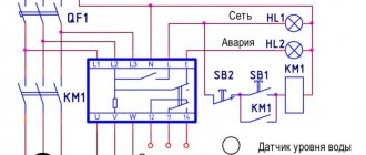
Connection diagrams for the UZM51M protection device
Installation of the device is standard: in a common line on 35 mm DIP rails using quick-release fasteners.
There are no restrictions on the relative placement of the UZM: neither temperature nor installation.
Connection to a single-phase network is carried out as follows:
- the phase line is connected to the “L” contacts, input (IN) and output (OUT);
- fixation is carried out using three types of screwdrivers, with the same degree of reliability;
- the zero line “N” can be connected in three ways: one-way connection to any “N” contact;
- end-to-end connection on both sides, as in a conventional circuit breaker;
- connection with forced opening of the “N” line at the input, for manual shutdown of the UZM based on the “zero missing” sign.
Connection to a three-phase network (three devices are used):
- phase lines are connected to the “L” contacts, input (IN) and output (OUT), as with a single-phase connection;
- the zero line “N” is connected one-way, to the input side of the UZM machines.
Analogs
Analogues of the UZM-51 device include the following devices:
- OM-63 from ;
- RN-106 from NovaTek.
RN-106 is a voltage relay that protects against unauthorized entry into an apartment with a voltage of 380 V. Too high a voltage leads to the failure of all household appliances connected to the network at that moment.
Voltage relay RN-106 prevents failure of home appliances
The OM-63 power limiter is used primarily in single-phase networks. The device immediately turns off the power supply to the home when the power consumption exceeds the established threshold. The device also protects electrical equipment connected to the network from the negative effects of significant voltage drops from nearby lightning strikes or the inclusion of overly powerful equipment.
Characteristics of arrester
The defining characteristic of the limiter is the maximum value of the operating voltage of alternating current, which is supplied to the terminals of the device without a time limit. There is no damage or thermal instability.
Another indicator is the conduction current that passes through the arrester. Its value is measured under real operating conditions and is usually equal to several hundred microamps.
Other characteristics include:
- The value of the maximum discharge current.
- Current carrying capacity.
- Short circuit resistance.
- Estimated current of switching overvoltage.
- Rated discharge current.
In addition, any surge suppressor can withstand slowly changing voltage values. In other words, the surge arrester should not be destroyed when the voltage is exceeded for a certain period of time.
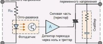
Any residential or administrative building is equipped with a large number of equipment powered from the electrical network. A significant increase in the operating voltage and current values in this network can lead to failure of all this electrical equipment. If service organizations are engaged in protection against such phenomena in apartment buildings, industrial and administrative buildings, then the owners of private houses must take care of it themselves. And a surge suppressor will help with this.
As the name suggests, an excessive voltage suppressor (SVR) serves to protect electrical equipment from voltages significantly exceeding their rated values. This high voltage, or in other words, overvoltage, is usually pulsed in nature. Therefore, another name for such devices is a pulse voltage limiter (PVO).
To better understand the applications of surge arresters, let us briefly consider the reasons that cause such voltage surges. Overvoltage pulses can be switching. In this case they arise as a result of:
- switching (switching) in powerful power electrical installations and energy supply systems;
- when there is a sudden change in load in distribution systems;
- when damage occurs in power installations causing a short circuit.
These cases are of an industrial nature and professionals are involved in eliminating their consequences. Industrial devices are installed in such circuits, for example, surge arrester-110, where the number 110 indicates the network voltage in kV. For us, it will be more interesting to protect against surge voltages of a private residential building. Typically, these overvoltages occur during a thunderstorm when lightning strikes. In this case, overvoltage pulses occur when:
- lightning strikes directly into a power line (power line) outside the house;
- A lightning discharge occurs between clouds or into an object located near the house. The resulting electromagnetic field induces a powerful impulse in electrical circuits;
- A lightning strike occurs in the ground near the house. The discharge current flowing in the ground can cause a significant potential difference.
In these cases, pulses of up to 10 kV can occur in external overhead lines up to 380V, and up to 6 kV in the internal wiring of houses. To avoid the harmful effects of such high voltages on the home electrical network and household electrical appliances, there are simple measures. According to the Electrical Installation Rules (PUE), surge voltage limiters (PVR) must be installed at the entrance of the power electrical cable to the house. The connection diagram for the EIN is simple. The device is connected to the circuit between the power cable and the ground loop. There are enough offers on the market from various manufacturers, one of which is the Energomera concern.
Switching off short-circuit currents
Another design criticism that worries many experienced electricians is the complete lack of any resemblance to arc chutes.
On the same UZM-51MD it is indicated that its maximum breaking capacity is 4.5 kA.
But here there is nothing. How will this affect the contacts during operation during switching shutdowns and switching ons? Not under normal conditions.
This can be explained primarily by the fact that the ultrasonic protection system should functionally only work in tandem with a circuit breaker or a differential switch, which is responsible for the entire function of short-circuit protection and disconnection of emergency current loads.
At short-circuit currents up to 6 kA, the contacts of the ultrasonic device will be closed and its main task is to “endure” and pass this current through itself without consequences, which it successfully copes with. It is precisely the circuit breaker that should break an arc of such magnitude.
Device and appearance
UZM-50M and 51M, 16M consists of two parts. There is a varistor at the input - it smoothes out short-term surges or sags in voltage that occur when equipment with electric motors is turned on. At the output there is an electromagnetic relay that turns off the load when there is dangerous voltage in the network. Models 51 MD and 50 MD add another device - spark detection. So the modification with the letters “MD” is fireproof.
The terminals can connect conductors with a cross-section of no more than 35 mm² (in the UZM 16 model, wires up to 2.5 mm²). Line wires are connected to the upper terminals, the load - to the lower ones. When triggered, only the phase wires are broken, the neutral is not switched. She goes straight to the exit. Any of the devices can be installed either at the entrance to a house or apartment, or at individual groups of consumers.
External differences are clearly visible. UZM-50MC has a digital indicator, thanks to which you can quickly monitor voltage, current and power
The front panel of various modifications may have significant differences. However, any model has operation/emergency shutdown indicators (green - in operation, red - disabled). There is an LED that changes color depending on whether a shutdown occurred due to an “arc” or due to emergency voltage parameters. There are also manual control buttons, in the UZM-51MD modification there are knobs for adjusting the limits for turning on and off the power supply.
This is interesting: Wi-Fi relay Sonoff - operating principle, types and connection diagram
Models and their characteristics
Meander's assortment today includes six UZM models for single-phase networks and one for three-phase networks. The parameters are basically the same, the functionality differs. Models are available in two climatic options (except for 50Ts, which is only available in the UHL4 version). What is the difference between UHL 2 and UHL 4? UHL2 tolerates lower temperatures:
- UHL 4 can operate at temperatures from -25°C to +55°C,
- UHL 2 operates from -40°C to +55°C.
Once again: the difference between UHL 4 and UHL 2 is only in the lower temperature limit. UHL 2 is more “frost-resistant”. They should be used in the northern regions of the country when installed outdoors. When installed in a heated room, the climatic design does not play a role.
A few words about UZM 16. It is also designed to turn off the power in the event of a decrease or increase in voltage and smooth out pulse surges. But you can connect wires with a cross-section of up to 2.5 mm² to it. The rated load current is 16 A. This means that the device can be installed on separate groups of consumers. It can also be used in the country if the total load does not exceed 4 kW.
Where to install UZM
As we said earlier, a voltage relay can be installed at the entrance to an apartment or house, or at all or some groups of consumers. Sometimes it can be difficult to choose a place to install the UZM. What can be said for sure is that it is placed after the introductory machine and, most often, after the electric meter. In principle, it can be installed before the meter, but only if the operating organization agrees. And they rarely give consent to this. Therefore, usually, the UZM is placed after the meter.
Two scheme options with UZM
The power supply circuit may also contain a fire protection RCD. So where should you put the surge protection device? Before the fire protection RCD or after? If you put it in front, then when the power is turned off it will be out of action. And if after, it may be damaged as a result of jumps. In general, decisions here are made individually. We can definitely say that the voltage relay must be installed before the first branch to consumers.
Connection in three-phase networks
There are special models of protective modules for three-phase networks - UZM-3-63. All three phases are connected to this device at once, and further supplied from the output. When triggered, all phases are switched off simultaneously, so that the power is lost completely. This is not always convenient, since problems usually arise with one of the phases.
Connecting a three-phase UZM
The issue can be resolved by installing one UZM for each phase. Then, if there is a imbalance at some phase, the rest will be in operation. It's more convenient. But this connection method - three single-phase UZMs - is not suitable if there is a three-phase load. In this case, when installing three separate UZMs, when disconnected in one of the phases, there may be a “flow” through the load to the adjacent one. So the choice is yours.
What is the difference between UZM and RCD?
It must be said that the overvoltage protection relay in any version does not replace the RCD or circuit breaker. These devices complement each other, making protection more reliable:
- The machine ensures that the wiring does not overheat.
- The RCD turns off the power when leaks occur - insulation breakdown or when a person touches live parts.
- The UZM monitors the mains voltage, turning off the power if the parameters go beyond the established limits.
Functions of various household electrical protection devices
As you can see, all three devices are needed. As a rule, when assembling a panel for a house or apartment, they neglect to install the voltage relay. This is extremely short-sighted, because UZM extends the life of electrical appliances and electrical equipment in conditions of unstable network voltage. In the version with spark detection - 51MD and 50MD - it also increases fire safety. Which is very important in wooden and frame houses, but not only for them. According to statistics, about 15% of fires occur due to a spark in the wiring. So monitoring sparking is really important.
Principle of operation
Using the regulators installed on the device body, you can set the relay operation limit for the upper voltage from 240 V to 290 V and for the lower voltage from 210 V to 100 V.
When connected to the power supply, the indication on the UZM-51M does not work within the first 5 s. A flashing green light indicates that voltage testing is in progress. If it corresponds to the specified parameters, the electromagnetic relay turns on, and this is indicated by the uniform illumination of the yellow and green LEDs.
In normal operation, the UZM-51M controller constantly monitors the voltage level, and the varistor dampens its pulses to an acceptable value.
The operation of the light indication differs in different emergency modes.
A flashing red indicator warns that the voltage is significantly higher than normal.
If the yellow LED goes out and the red LED lights up continuously, it means that the voltage has exceeded the set value and the relay has disconnected the load.
A flashing green indicator indicates that the restart time countdown has begun.
The green and yellow LEDs, which are constantly on, indicate that the voltage has completely returned to normal and the relay is turned on.
If the green LED on the panel begins to blink while the yellow LED is constantly on, it means that the incoming voltage has decreased significantly.
The flashing lower indicator, which has changed from green to red, signals that the countdown of the electromagnetic relay switch-off time has begun.
The red LED flashes every two seconds and the yellow one goes out to indicate that the relay is turned off.
When the voltage normalizes, the alarm works as in the first case.
Alternately flashing red and green lights remind you to start the device by pressing the test button again.
Voltage relay Zubr
The company produces both relays for installation on a DIN rail in an electrical panel (the entire apartment is powered) and for connecting a separate device through a socket. The maximum load for the socket type does not exceed 16A. The voltage indication on the display starts to appear at 80V; if “U” is lower, the display goes out. The accuracy of the measured voltage readings is very good with an error of no more than 1-2 Volts.
Settings
The relay has three buttons for adjustment and settings:
- ⚡
upper for setting the maximum response threshold - ⚡
lower for setting the minimum response threshold - ⚡
medium for setting the restart time. The factory setting is 3 seconds.
There is also an autonomous settings memory. Once set, the relay will remember all settings and settings. Be sure to set the turn-on time delay.
In the event of a general power failure (even a planned blackout in the entire house or area) and the voltage is supplied again after a certain time, thanks to the Zubr voltage relay, light will appear in your apartment a few seconds after everyone else.
Thus, you will be spared from numerous troubles and transient processes that occur when the power is turned on from the substation. This is one of the advantages of using a 220V voltage relay for the home, which few people think about.
After long-term use, do not forget to tighten the contacts on the terminals. Since certain types with thermal protection (with the letter t) will begin to trigger falsely due to overheating.
The seat for the DIN rail is made with a large margin. On the one hand, this is a plus, because... Suitable for any rail with non-compliance with dimensions. On the other hand, there is a minus: when installed on a standard one, it will “lobble”, and for rigid fixation you will need plugs.
More features:
- ⚡
Rated currents 25-32-40-50-63A. The current reserve is approximately 20%. That is, for a short time a 50A relay can withstand a current of 60A (do not confuse it with the shutdown current!) - ⚡
Response voltage adjustment step – 1 Volt - ⚡
The step for adjusting the re-activation time is 3 seconds - ⚡
The letter t in the name of some relays indicates that the product has thermal protection against internal overheating. For example, if the contacts and its body heat up to 80 degrees, the relay will turn off, even without voltage surges - ⚡
In width (53mm) on a DIN rail, the Zubr relay occupies 3 modules - ⚡
If the rated current of the relay is less than the current of the machine installed in front of it, it must be used in conjunction with a contactor.
The average price in online stores for the most popular Zubr voltage relay model for an apartment 40A with a thermal release (brand D40t) is about 3,000 rubles. A socket type relay will cost half as much.
View the technical data sheet of the Zubr relay
Zubr relay connection diagram:
Purpose and scope
UZM-51M (multifunctional protective device) is used to protect electrical equipment from voltage surges in single-phase electrical networks of any premises.
This device turns off consumption sources when the supply voltage increases or decreases, and also dampens its pulsed high-voltage surges. The reasons for these deviations may be different:
- overload of transformer substations;
- turning on powerful asynchronous motors and welding machines;
- short circuit or break of the neutral wire;
- lightning striking a power line.
UZM-51M is usually used in household electrical networks, installed after the electric meter and circuit breaker at the power supply input to the room. It can also be used in three-phase networks.
Why do you need UZM-51M and how to connect it?
Appearance and design
You can see what the UZM-51M looks like in the photo below:
As for the design of the device, the multifunctional protection device is a voltage control relay with a powerful electromagnetic relay at the output, which is additionally equipped with varistor protection. The terminals have a tunnel design, making it possible to clamp wires with a cross-section of no more than 35 mm2. The front side of the UZM is equipped with two indicators.
The first one signals the “Normal” and “Emergency” states, green and red, respectively. The second, yellow, signals that the relay contacts are turned on. In addition, on the front side there is a “Test” button, intended for manual control of the device (you can turn on the load yourself).
Just like the voltage relay, the UZM-51M has regulators for the upper and lower protection thresholds.
Main settings
note
Technical characteristics of UZM-51M (rated and maximum current, response thresholds, etc.) are summarized in the table below:
Principle of operation
It is also important to explain how the UZM-51M works. After turning on the device to the network, there is a time delay before turning on, at this moment the input voltage is measured
If the voltage is within acceptable limits, the green indicator turns on - the device is ready for operation, power is supplied to consumers.
Otherwise, the yellow indicator lights up and the load is not connected to the network. If during operation of the UZM the voltage approaches the upper threshold, the yellow LED begins to flicker, and when it goes beyond it, the load is turned off and the red light comes on. This signals that the set parameters have been exceeded.
In the case when the voltage drops to the lower threshold, the green LED begins to flicker, and when it goes beyond the set limits, the red indicator lights up and flickers. When you press the “Test” button on the device body, the red and green LEDs switch alternately, and the load is disconnected from networks.
To return to working condition, you must press the “Test” button again.
Connection diagram
The second figure shows a three-wire circuit, where the phase wire enters and exits the device, and zero is used to power the UZM circuit.
On the third there is a remote control circuit for the UZM, the zero through the switch powers the device, and the phase is switched by the device, supplying voltage to the load.
We also recommend looking at the diagram on how to connect the UZM to a single-phase network in an apartment or house:
What problems exist in a home network and how to protect subscriber networks from parameter discrepancies
- exceeding the permissible voltage by more than 10%;
- reduction in network voltage (sag) by more than 10%;
- short-term sudden increase or decrease in voltage;
- alternating current frequency change;
- sparking, arcing on contacts when a powerful consumer is turned on;
- zero break, as a result - phase imbalance;
- short circuit on the line or inside the electrical appliance.
Some of these problems arise due to the fault of the user (maintaining equipment and lines in poor condition), some due to the fault of the energy supply company. Let's talk about this in more detail.
The quality of energy supply depends on a number of reasons:
- deterioration and compliance with the design load of power lines;
- technical condition (and actual availability) of transformer substations on each subscriber line;
- the functionality of the automation to maintain normal electrical network parameters;
- load distribution between phases;
- legality of connecting new subscribers (there are cases of exceeding technical specifications).
Let's give an example
Condition: three-phase input into a multi-storey building, common zero, phases “A”, “B” and “C” are evenly distributed between entrances 1, 2 and 3. For any reason (corrosion, mechanical damage, etc.) the zero breaks. At this time, entrance 1 is at maximum load (boilers, electric ovens), entrance 2 is at medium load (refrigerators, lighting), entrance 3 is at minimum load (a couple of TVs and several computers).
What will happen with each phase?
- Phase "A" - 1 entrance. The voltage will drop to a minimum value, close to zero.
- Phase “B” – 2nd entrance. With a high degree of probability, the voltage will remain within 220 V, although a floating change in potential is possible.
- Phase “C” – 3rd entrance. On a line with minimal load, the voltage approaches the value between phases, that is, about 380 V.
Since the operating current for each connected subscriber (group of subscribers) did not exceed the set value, the current protection circuit breaker will not work. Electrical appliances on line “C” (3rd entrance) will fail, or in the worst case, they will simply burn out. Often this situation leads to a fire.
As a rule, we don’t think about the fact that the electricity connection to our meter is not single-phase at all. This applies not only to holiday villages and small villages. Any subscriber network in cities, be it Moscow or a regional center in the Far East, is created according to a single principle.
You can install an individual transformer substation or a powerful stabilizer. But the cost of such equipment may exceed losses in an emergency on a 220 V line. What is the solution? Install the UZM protection device.
Information: Among home electricians, multifunctional ultrasonic automatic devices are popular, which also protect against power surges, arcs or sparks.
In terms of operation reliability and degree of protection, the devices are similar. However, the protection device is multifunctional: for example, UZM 51M, closes the circuit independently after restoring the power supply parameters. But the AFIS must be turned on manually.
Connection diagrams
The diagrams by which UZM-51 is connected are shown in Figures 1-3.
Connection diagrams for UZM-51 depending on the number of wires and the presence of remote control
- When connecting four wires, the input conductor is placed at the top, and the output for electrical appliances is at the bottom.
- If three wires are connected, then the phase is passed through the UZM, “zero” is required to power the device itself.
- When connecting the remote control, “zero” passes through the switch, the device itself is switched through the power cable, and the load and voltage are supplied.
Connection diagram of the UZM-51 device to a three-phase network indicating the main dimensions
Voltage relay RN-111 and varieties RN-113, RN-111M
This relay is mainly used in conjunction with a contactor, since a load of no more than 16A (3.5 kW) can be directly connected through it.
Pay attention to the wires with which you will power the RN-111 relay; they should have a cross-section of no more than 4-6mm2.
And then if it’s a single core. For stranded ones with the condition of subsequent crimping with NShVI lugs, it is best to use only 4mm2, otherwise the cores simply will not fit into the terminal clamps.
To connect a larger load (up to 7 kW), you can purchase RN-113. But its contacts are also quite weak, so to directly connect the load through a relay, it is better to divide the declared rated current by 1.5 times. The light indicator board is available only for brands with the letter M and RN-113.
The indication begins to appear at a voltage of 40V. The error in readings of the measured voltage in the range from 175 to 350V is 1-2 Volts.
Connecting relay RN-111,111M,113
Data sheet for relay RN-111
Technical data sheet of relay RN-111M
Technical data sheet of relay RN-113
Design
The general structure of any UZM is conventionally divided into two parts. The input is equipped with a varistor, which smoothes out short-term voltage surges or drops. A power relay is installed at the output, disconnecting the load in dangerous situations. MD modifications are additionally equipped with means for detecting sparks in wiring. All devices are designed for DIN rail mounting.
The input terminals are installed in the upper part of the plastic case, and the output terminals are installed in the lower part. Their dimensions are quite sufficient for connecting conductors with a cross-sectional area of up to 35 mm2. At the moment the UZM is triggered, only the phase conductor breaks, since the neutral does not participate in the switching processes. It passes through the entire device from input to output. The UZM protection device can be installed at the input or connected to the lines of individual consumer groups.
The front panels in different UZM models differ significantly in their content. What is common is the presence of operating and emergency mode indicators with green and red LEDs. Individual indicators indicate the cause of the shutdown - a voltage drop or an electric arc. Adjustment knobs are also installed that set the upper and lower voltage limits at which the power is turned off and on. Almost all UZMs have a manual control button, used in special cases.
On the side panel there is a general diagram of the device and a circuit diagram for connecting the UZM. Varistors installed at the input perform several functions. The first is designed for 680 volts. It limits low-power pulsed switching overloads. The second varistor can withstand 620 volts and provides power protection. The entire operation of the UZM is controlled by a special controller.
What is UZM, and on what principle does the automation work?
Essentially, this is a voltage control relay designed to interrupt the supply of electricity in case of deviation from the parameters. Imagine a circuit consisting of a control module, a control and signaling device, and a disconnecting system. This is exactly how the multifunctional protection device, that is, the UZM, is designed.
UZM 50M and UZM51M are made in a standard closed housing 2DIN wide, and are intended for installation in distribution cabinets on a DIN rail 35 mm wide (GOST R IEC 60715-2003).
Components and description of the voltage control relay:
- electronic control components with mechanical installation of resistors for triggering voltage thresholds;
- LED signaling elements about the state of the supply voltage;
- current shunt;
- varistor protection;
- testing module with a “test” button;
- powerful electromagnetic relay providing load connection of power circuits;
Structurally, all elements (including power ones) are made on one circuit board. This arrangement ensures structural rigidity and effective heat removal from the circuit elements.
Connection of conductors with a cross-section of up to 35 mm² is made through high-strength tunnel clamps with front screws. To eliminate wiring errors, the terminals are equipped with protective flags (so-called “fool proof”).
The light indication changes color depending on the power supply mode (emergency or normal). The user can visually determine whether the UZM 50 or 51M protection device is turned on or not, as well as assess the state of the electrical network.
Schematic diagram of the device:
The control circuit is implemented on a ready-made PIC12F683 module; the remaining radio components ensure the operation of electronic switches assembled on transistors. The diagram clearly shows that the response thresholds of the lower and upper voltage barriers are provided by variable resistors R18 and R19. The adjustment is not smooth, but stepwise, in 10 positions.
The MP25-1 power relay has one pair of contacts, only on the phase wire. Thanks to this scheme, the neutral wire after the UZM voltage control relay is always closed to ensure the normal operation of other circuit breakers. In addition, this scheme for passing the zero bus allows you to connect the UZM not by passing through the “N” line, but by tapping on one side.
To protect against surge voltages that occur when connecting electrical installations, a powerful varistor with a diameter of 20 mm is designed.
Its own power supply circuit ensures the operability of all device systems, including the power winding of the MP25-1 relay. Since the connection and control circuit of the UZM 51M must operate when the line voltage is turned off, it is necessary to provide a backup power source. For this purpose, a storage capacitor C1 is provided, the capacity of which is sufficient to connect all protection and control modules.
Principle of operation
It is also important to explain how the UZM-51M works. After turning on the device to the network, there is a time delay before turning on, at this moment the input voltage is measured
If the voltage is within acceptable limits, the green indicator turns on - the device is ready for operation, power is supplied to consumers. Otherwise, the yellow indicator lights up and the load is not connected to the network.
If during operation of the UZM the voltage approaches the upper threshold, the yellow LED begins to flicker, and when it goes beyond it, the load is turned off and the red light comes on. This signals that the set parameters have been exceeded. In the case when the voltage drops to the lower threshold, the green LED begins to flicker, and when it goes beyond the set limits, the red indicator lights up and flickers.
When you press the “Test” button on the device body, the red and green LEDs switch alternately, and the load is disconnected from the network. To return to working condition, you must press the “Test” button again.
Operating principle
The regulators located on the device body are controlled with a screwdriver. The upper regulator allows you to set the voltage in the range from 240 to 290 V, the lower – from 100 to 210 V. When measuring voltage, an error of up to 3% is allowed.
During testing, there is a delay of 5 seconds and subsequent activation of the green indicator with the inclusion of an internal relay. If the voltage meets the standards, two lights light up - green and yellow. Quick start is activated by pressing the test button.
After a voltage drop and its return to normal within a certain interval, the relay turns on after 10 seconds. It is possible to configure the relay response after a drop. The setting is made in the range from 10 seconds to 6 minutes, other values are not provided.
To configure:
- turn off the device by pressing the test button;
- Press and hold the button again until the green indicator blinks repeatedly - the response time of the device will be set to 10 seconds;
- When the red light comes on, the time is 6 minutes;
- Release the button and press it again to restart the device.
It should be understood that pressing the button that switches the device to test mode affects the trouble-free operation of the UZM in the event of an emergency. When the voltage approaches the highest value, the red indicator begins to blink. Exceeding the permissible threshold leads to the deactivation of the yellow light and the red light comes on.
When the voltage drops below the set value, the green indicator starts blinking first, then the timer is activated until the red indicator turns off and blinks. Then the red light comes on with a two-second delay, and the yellow light turns off. After the voltage stabilizes, a timer is activated, showing how many minutes and seconds remain before connection. At the same time, the green indicator continues to blink. If the network parameters do not correspond to the set ones, the time is reset to zero and a new countdown begins. After the delay time has expired, the UZM is turned on.
When the red and green lights blink alternately, it is necessary to turn off the relay using the test button. When you press it again and hold it for two seconds, the relay starts working in normal mode.
Turning on the UZM-51 breaks the power cable, the “zero” is set through and cannot be switched. One-sided zero connection is also allowed, so that zero phases can be connected from below three-phase lines.
Appearance and design
UZM-51M, like other modular devices, is mounted on a standard DIN rail. The relay housing is plastic, with two upper and two lower tunnel-type terminals.
On the front of the panel there are two rotating regulators that set the maximum and minimum voltage limits for the relay to operate, two transparent eyes and a “Test” button between them.
The lower eye glowing red means the emergency mode is turned on. The green glow shows that everything is normal. If the top eye glows yellow, it means that the electromagnetic relay contacts are closed.
The test button not only turns the device on and off, but also sets the restart time.
Inside the case there is an electromagnetic relay, a microcontroller and a varistor. The relay contacts break the phase wire, and the neutral wire passes directly through the housing as a bus.
Tags: , automatic, ampere, sconce, varistor, upper, view, choice, switch, house, , clamp, sign, measurement, pulse, cable, like, design, circuit, , light bulb, , magnet, installation, power, load, voltage, neutral, nominal, limiter, skew, overvoltage, transfer, connection, potential, principle, wire, start, , work, size, regulator, relay, row, light, LED, network, system, circuit, ten, type, current , transformer, , installation, phase, photo, shield
How does it work
The action of relays is best considered in different situations, since in each case they react differently, although the principle of operation is the same.
At the moment of power supply or restart of the UZM voltage relay, the following actions are performed:
- Nothing happens for 5 seconds. During this pause, the network parameters and the functionality of the device itself are checked.
- When the voltage is normal, a green flashing light comes on. It continues for the time delay set by the user to turn on the load. This period is 10 seconds or 6 minutes and is set during the very first start of the device.
- At the end of the delay period, the yellow LED lights up, and the green LED stops blinking and remains lit. Therefore, the device is in normal operating mode.
When selecting a long 6-minute waiting interval and needing to speed up the device’s startup, use the TEST button. Once pressed, the relay is automatically tested and then switched on immediately.
If an arc current is detected in the network, this is signaled by two LEDs at once - “fault” and “arc”. The load is immediately turned off and after 30 seconds a restart attempt is made with the set delay. If sparking is detected again within 20 minutes, the power will be turned off for 4 minutes, after which the condition will be monitored again.
When sparking is detected for the third time, the power will be completely turned off and will not turn on automatically. Starting is done manually, and if there are deviations, the device will not turn on. If everything is in order, then connecting the device and the operation of the indicators will be the same as during the first start.