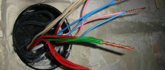
One of the stages of electrical installation work is the connection of wires in junction boxes, which follows immediately after wiring and laying cables. According to the Electrical Installation Rules (ELR), electrical connections of wires must be made only in junction boxes.
Today, there are many ways to connect wires in a junction box. The choice of connection type depends on the following factors: core material - copper, steel or aluminum; working conditions - on the street or in an apartment; number of conductors - two, three, four; the cross-section of the cores is the same or different. Based on these factors, the most suitable and correct method is selected.
Why do you need a junction box?
Quite often there is some neglect of the distribution box (junction box). Some people think that using it when laying wires is a waste of time. After all, it still needs to be fixed to the surface, and this is additional effort. It is much easier, for example, to twist the conductors, insulate the junction and “roll up” everything with plaster.
- But this overlooks some issues:
- During operation, free access to the wire connections must be provided. For example, if there is no light in some room or the socket does not work? The test showed that the reason was the lack of voltage. How to find a distribution box in an apartment or a faulty section of the circuit? Tearing off wallpaper, breaking plaster to gain access to twisted wires?
- If in the future you need, for example, to install one more (two, three) sockets. Connect them “in parallel” from the first? Is this always convenient? While connecting new wires in the distribution box will not be difficult;
- Proper connection of wires is using terminal connectors. How deep do you need to drill a “channel” in the wall in order to hide the terminal block there?
- In terms of fire safety, the advantage of such a box is undeniable.
Safety precautions
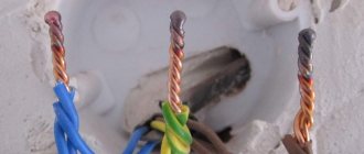
- When connecting wires , you must be careful and strictly follow the operating instructions, which prohibit simple twisting (twisting in a spiral) of wire made of aluminum and any other metal (copper, aluminum-copper, aluminum). The reason is that when aluminum oxidizes, it releases galvanic vapor, which will sooner or later break the contact, and sparks that occur when high-power currents pass through such contacts often cause a fire.
- Aluminum welding is the most traumatic - to avoid trouble, be sure to use rubber boots and a welding helmet.
- in the room where welding is carried out to prevent fire.
- Even wooden floors are recommended to be covered with iron sheets.
Read also: Steel x13 for knives
Wire connection methods
Special Electrical Installation Rules (PEU) regulate the correct connection of electrical conductors by welding, soldering, crimping or using screw and bolt clamps. The rules do not stipulate the most common connection method - twisting. Although a properly performed twist is more reliable than a poor solder connection.
- The choice of connection method depends on several factors:
- materials to be joined. It can be aluminum, copper or a combination of both;
- number of cores in the connection. You can connect not only two, but also three, four or more wires;
- circuit load;
- cross-section and number of cores.
Twisting wires
To make such a connection, you need to strip the ends of the wires, carefully twist them with pliers and insulate the twisted area. Very simple and without material costs. But such a connection weakens over time due to residual elastic deformation of the material, which means that the resistance in the connection increases and the contact begins to heat up to the point of destruction and fire.
Therefore, in no case should you lay twisted wiring on flammable substrates, for example, in a wooden house. And one more prohibition - poor protection against moisture does not allow such a connection to be made in rooms with high humidity. In this way, it is strictly forbidden to connect dissimilar materials, multi-core cables with single-core cables and at a current of more than 3 A.
In order for the twist to be of high quality, you need to remove up to 80 mm of insulation from the wires, fold them perpendicular to each other if there are two of them, and parallel if there are three or more, and twist them tightly. The remaining ends of the wires must be removed with pliers in a screw motion, as if smearing the material of the wires into one another.
The total length of the finished twist should be at least ten, and preferably fifteen, diameters of the cores. If special caps or heat-shrinkable tube (cambric) are used for insulation, they are put on the wire before twisting.
It is recommended to put on the heat shrink tube twice, and lay the insulating tape in at least three layers. Whatever insulating material is chosen, it must also capture the wires’ own insulation to protect it from moisture and slippage.
Soldering wires
This method is the best in terms of its combination of manufacturability and reliability, but requires some skills to make a quality connection. Before soldering, the wires must be thoroughly cleaned of insulation and oxides, tinned if necessary and twisted not as tightly as with simple twisting, coated with flux and soldered.
By soldering you can connect both copper and, with some skill, aluminum wires, with suitable flux and solder. Do not use active acid flux, as it will destroy the connection by remaining on the exposed wires. The connection point is isolated in the usual way. The distribution box in this case is called a junction box
- Despite the undeniable advantages, this method also has quite significant disadvantages:
- the need for skills in work, the complexity of the process;
- use of a special tool;
- permanent connection, that is, for repair it must be completely removed;
- an increase in resistance in the connection over time, which deteriorates electrical conductivity and increases voltage losses in the network.
Welding wires
Welding is an even more reliable connection method than soldering, but it requires a welding machine with personal protective equipment and welding skills, which is much less common in everyday life. Unless you need to carry out electrical installation work in a country house yourself, then purchasing an inverter-type welding machine will be economically justified.
Welding inverters are small-sized, have a wide range of welding current control, and provide stable arc burning with low power consumption. To weld copper wires, carbon-copper electrodes or carbon rods from ordinary AA batteries are used.
Preparation for welding differs only in the density of the twist and the fact that the free ends of the two wires, even if there are more of them in the connection, are straightened and pressed parallel to each other to facilitate the formation of a melt ball. Then the twist is placed in a welding clamp (regular old pliers) and the ends of the wire are welded with a carbon electrode to the main twist for two to three seconds so that the insulation does not melt. After cooling, the welding site is isolated in the usual way.
There is often a temptation not to wait for natural cooling, but to use cold water to speed up the wiring installation process. But cold water causes microcracks to appear in the material, which naturally affects the quality of the connection.
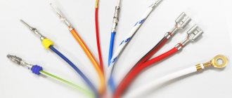
Wire crimping
This method of connecting electrical wires uses special tubular sleeves or lugs. The industry produces sleeves for wires with a cross-section from 2.5 to 240 mm², and it is very important to choose the right connectors for electrical wires specifically for each connection.
To perform the work you need a special tool. This may be a crimping press or tongs, mechanical, electrical or hydraulic. Having selected a suitable sleeve and adjusted the tool, remove the insulation from the wires, strip the ends and apply quartz-vaseline paste to them, put on the connector and crimp.
If the tool is simple, then you need to perform several compressions at some distance from each other. Using a good tool, you can crimp the sleeve in one go. At the end, the usual insulation of the joint is performed.
The wires to be connected can be inserted into the connector from opposite sides so that their joint is approximately in the middle of the sleeve. It can be convenient to insert both wires on one side, and the total cross-sectional area of all wires should be less than the cross-section of the sleeve. High-quality installation and reliable insulation are the positive aspects of using crimping.
- But there are also negative points:
- the sleeve is deformed during crimping and its reuse is impossible;
- the need for a special tool for crimping the sleeve, adjusting it to length and removing insulation from the conductor;
- to crimp the connection of copper and aluminum wires, you need a rather rare special sleeve;
- Quite a lot of time is spent on installing electrical wiring.
Using clips (PPE)
The clamp is a cap with a square steel wire coiled into a spiral cone. For aluminum wires, the cone is filled with a special paste that prevents oxidation of the exposed ends. Information on the packaging with clamps will allow you to choose the correct size of personal protective equipment in accordance with the cross-sectional area and the number of connected conductors.
To connect the wires, their ends are stripped to a distance slightly less than the depth of the cap, folded together, slightly twisted, and the cap is screwed on top. There is no need to clean bare wires from oxides, since this work is performed by the edges of the spring, and its turns tightly press the cable cores to each other.
The use of such connectors is technologically advanced; they not only connect wires, but also insulate the junction, although they do not provide the same contact area as when twisted and soldered. The bright colors of the caps help to mark zero, phase and ground during installation if the wires do not have color markings.
- The disadvantages include:
- gradual weakening of the spring over time, and, consequently, an increase in contact resistance and voltage losses in the network;
- restrictions on the number of connected wires, you can connect two with a cross-section of 4 mm² or four with a cross-sectional area of 1.5 mm²;
- impossibility of mixed connections.
Bolted connections
Connection using a bolt is a simple, reliable and effective method. You just need to have a short bolt of small cross-section, three washers and a nut. True, such a connection takes a lot of electrical tape, and it is not used in the distribution box due to its bulkiness. Put a washer on the bolt, then screw on the stripped wire, another washer (if connecting copper and aluminum), a second wire, a washer and tighten the nut tightly.
Screw terminals
Screw terminals allow for quick and neat installation. They are widely used when connecting lamps, switches, and sockets to wires. They can be used to connect copper and aluminum without the need to insulate the connections.
- The disadvantages of screw clamps include:
- the need for crimping or soldering a multi-core cable before installation;
- the need for periodic maintenance of connections, since the screws need to be tightened, that is, access to them is required.
Walnut clamp
This connector is named for its shape. It is a cable clamp with special plates with grooves for wires and four screws in the corners. The wires are stripped, inserted under the plate and secured with screws. Then the carbolite shell is put on.
With this clamp you can connect copper and aluminum, the insulation is quite reliable, the installation process is simple and does not cause difficulties. Basically, this outlet connection is used to drain apartments from a common aluminum riser. But besides tightening the threaded connections, there is another drawback - the dimensions, due to which the “nut” does not fit into the junction box.
Terminal blocks
Connection using terminal blocks is used in distribution boxes, when installing lamps, sockets and switches. The terminal blocks are small in size and easily fit into a box. A brass bushing is inserted into a small plastic case, into which screws are screwed on both sides.
Stripped conductors are inserted from the ends of the block and clamped with screws with force. For wires of different sections, terminal blocks with different inlet holes are designed.
- The quality of such a connection is high, installation is easy, dissimilar materials can be connected, but there are also significant disadvantages of terminal blocks:
- connecting only two wires;
- poor quality of the pads themselves, which can cause disruptions in the network;
- Care is needed when installing aluminum and stranded wires so as not to damage the contact due to the fragility of the metal.
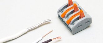
WAGO connection terminals
This relatively new type of connection using insulated spring clamps (connectors) is the most reliable and safe today. Disputes regarding the reliability of connections using Wago terminals may be associated either with counterfeits on the market or with the wrong choice of terminal for a specific load.
International certificates and approvals protect the reputation of these products. Their only drawback is their high cost. A special screwless spring mechanism makes installation of connections simple and quick. Vags for connecting wires can be reusable with a special lever that clamps the wire and releases it if necessary.
How to use Wago terminal blocks? Disposable terminals fix the core with some effort, but, according to manufacturers, it is impossible to release it. For installation, you only need to strip the ends of the wires and insert them into the clamp.
- Advantages of WAGO terminals:
- possibility of mounting dissimilar metals;
- possibility of fixing more than two wires at the same time;
- neat fixation of thin wires;
- good connection quality;
- compact sizes.
Reasons for incompatibility
The main reasons for the undesirable connection between these two metals lies in the aluminum wire.
There are three reasons, but they all lead to the same result - over time, the contact connection of the wires weakens, begins to overheat, the insulation melts and a short circuit occurs.
- Aluminum wire has the ability to oxidize when exposed to moisture in the air. This happens much faster when in contact with copper. The oxide layer has a resistivity value greater than that of the aluminum metal itself, which leads to excessive heating of the conductor.
- Compared to copper conductor, aluminum is softer and has lower electrical conductivity, due to which it heats up more. During operation, the conductors heat up and cool down many times, resulting in several cycles of expansion and contraction. But aluminum and copper have a large difference in the magnitude of linear expansion, so a change in temperature leads to a weakening of the contact connection, and weak contact is always the cause of strong heating.
- The third reason is that copper and aluminum are galvanically incompatible. If you twist them, then when an electric current passes through such a unit, even with minimal humidity, a chemical electrolysis reaction will occur. This, in turn, causes corrosion, as a result of which the contact connection is again broken, and as a result, heating, melting of the insulation, short circuit, and fire.
Detailed connection diagram
During operation of the electrical wiring, malfunctions may occur - for example, a circuit break has occurred. If during electrical installation the workers did without switchboards. boxes, and the joints were simply rolled up with a finishing material such as plaster, then in order to get to the joints again, you will have to disturb the external finish - tear off the wallpaper, break the layer of plaster, etc.
It is unlikely that anyone will be satisfied with such prospects. If in the future you need to install additional sockets, then in such cases it is not always convenient to pull wires from previously installed sockets; it is easier to organize the connection directly to the box.
If the wires are connected using terminal blocks, then you will have to drill a fairly deep channel into the wall, which is much more labor-intensive than a simple connection in a junction box.
Finally, from a fire safety point of view, the advantage of using junction boxes is undeniable. For the correct organization of electrical installation work, there are special Rules for the Construction of Electrical Installations (PUE), which also regulate the procedure for connecting electrical wires.
Solving other problems
The connection of stranded wires has a number of features.
Connecting many wires
Options for connecting two contacts were discussed above. If we are talking about connecting multiple contacts, it is recommended to choose among the following options (in order of priority - from the best method to the worst):
- Wago terminal blocks;
- crimping with sleeves;
- rations;
- twists;
- insulating tape.
The rules for docking using the indicated methods, as well as their advantages and disadvantages, are discussed above.
Docking of cores with different sections
To combine cores of unequal cross-sections in a junction box, you will need Wago terminal blocks, although you can get by with standard terminal blocks - the latter option will be cheaper. In this case, it is necessary to secure the cores tightly using a screw or lever.
Note! If the wires not only have different cross-sections, but are also made of different metals, you will need special pads, inside of which there is a special composition to prevent oxidative processes. Similar pads are available in the Wago range.
Cores with different sections can also be secured by soldering.
Joining of stranded and single-core conductors
The combination of conductors with one and multiple cores is carried out in the same way as all others. In this regard, you can choose any of the above methods, but the highest priority is soldering or terminals (preferably Wago).
Vags for connecting wires
One of the very important steps when installing electrical wiring is connecting the wires in the junction boxes. It is very important to make the connection in the junction box reliable, because subsequently, access to it may prove difficult, especially since in some modern houses the branch boxes are completely plastered over.
There are several different ways to connect wires: regular twisting with a layer of electrical tape (or heat shrink), twisting with welding of the ends, twisting with PPE (tip with a spring), connection using Wago clamps.
Which of these methods is better has been debated for a long time. Many cite various documents and regulations that state that connections must be made by welding. However, this rule is valid for aluminum wires, which are now practically not used anywhere. For copper, the reliability of welding is somewhat questionable, although it is still better than conventional twisting with electrical tape.
If you still decide to connect the wires by twisting them with electrical tape, then it is better to use heat-shrinkable tubing and wrap it with a small layer of electrical tape. The most optimal, in my opinion, is the connection using PPE (connecting insulating clamp) or Wago.
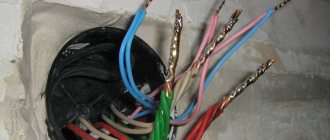
What we see after plastering the walls:
We take out the cables and clean the box. We cut the cables with a margin and make them the same length. I do about 70-90 mm, if measured from the wall.
Remove the insulation from the cable.
We clean the wires. The length of the bare copper section is about 30-40 mm
Then we twist it. It is convenient to do this with pliers. We bite off the ends a little.
Next, we put on PPE for the twist and twist it.
We wrap a layer of electrical tape over the PPE, I use black fabric electrical tape.
Then we carefully stuff everything into the box. After puttying, the box will need to be closed with a lid.
Below are photos of the connection using Wago clamps.
We expose the wires; the length of the exposed copper section should be about 8-10mm.
We insert the wires into the clamps and snap them into place. Make sure that the clamp holds the conductors well.
Then, carefully put everything into the box.
Alternative options
flat spring clamp
The wires can be connected to each other using a rivet. In principle, this technology is similar to screw technology, only here a rivet is used instead of a screw. The end result is a permanent connection.
This connection is made quite simply: both conductors are put on the rivet through a spring washer, then it is inserted into the rivet gun and the handles are pulled together until a click is heard.
There is also a special flat spring clamp. Such products are disposable and reusable, when the wire can be either inserted or removed. However, it should be remembered that such clamps are made of plastic, so it is not advisable to use them for currents exceeding 10 A.
Working with them is very simple: the wires are stripped and inserted into the clamp until they click. It is impossible to pull them out from there without using a special lever. It is also advisable to insulate this section of the wire.
Connection creation mechanism
Wiring your home is not difficult. To do this you need to have the necessary knowledge and equipment. The equipment is purchased in the store; you don’t even need to buy knowledge. At the very beginning, a diagram of the electrical network should be drawn up. In most cases, the owner of the construction hires an electrician who does not imagine the future location of the furniture and, as a result, switches are covered by doors, sockets in the corners are covered by furniture.
- As a rule, electricians draw diagrams with chalk on the wall of the future equipment, but it is better to place a diagram of the electrical network with the placement of electrical current collectors on the floor plan as a separate drawing, including the switching (connection) of the power cable cores in the distribution box - this will help:
- calculate the load on the electrical network;
- wire cross-section;
- divide consumers into groups.
- In terms of a household electrical circuit, there are at least two groups of electrical consumers:
- lighting;
- power part, that is, sockets.
It is best that these two circuits are mounted with separate power cables. If you plan to install powerful electrical appliances: electric stove, oven, boiler - these devices must have their own separate circuit, i.e. separate switch, fuse and cables.
Connection of wires in the junction box according to the PUE
PUE is a collection of regulatory documentation for the design and installation of electrical circuits; in fact, it is a desktop Bible for all people who begin to engage in electrical work. The collection shows the basic principles of creating circuits, the rules for their calculation, protection and communication devices. Further, all descriptions of electrical devices will be in accordance with the rules according to the PUE.
Selecting the cross-section and brand of wire
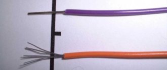
To lay electrical wiring in rooms and connect wires in a junction box, according to the PUE, the conductors must have a different color insulating coating, from the same manufacturer with the same color scheme. For wiring, it is best to use VVGNG brand wire - single-core copper, flat, double insulated, best with the additional designation NG, which means non-flammable.
It is best to purchase a cable from a well-known manufacturer, which must have a certificate. There is no need to take a wire without markings; electrical wiring in the house is, first of all, safety and is done for more than one year, so saving is inappropriate here. It must be taken into account that a copper cable with the same cross-section can withstand one and a half times more load than aluminum.
Attention! For a capital circuit, you cannot use a multi-core PVS or ShVVP cable. Although these wires are soft and more convenient to lay, they have a higher current resistance, and accordingly they will heat up more when a load is connected.
Power calculation
One of the basic rules for calculating the cable cross-section: used in the calculation of 1 sq. mm - 9 A. electric current, that is, a cable with a cross-section of 1 mm can withstand the load of a kettle or iron with a power of 2 kW.
- Based on these recommendations, at least the following should be used for wiring in the house:
- lighting core is 1.5mm square, which corresponds to 10 - 12A;
- sockets in rooms are 16A, which corresponds to a cross-section of 2.5 mm. sq.
- kitchen electric ovens, the wire for which must withstand 25A. - this is a 4mm section. kv;
- The core of a four-burner electric stove must withstand 32A. - cross section 6 mm2.
Correct choice of electrical connection. wires in the junction box depends on its cross-section. Attention! You cannot use electrical cables from different manufacturers, as they have different specific (ohmic) resistance per 1 linear meter.
Electrical junction box and wire connection
After laying the wires, according to the drawn up diagram, they must be connected to each other. In order for the connection to be in one place, there are communication boxes (distribution boxes). Depending on the installation, device connections can be round or square, deep or shallow, and are divided into internal (for hidden wiring) and external according to the method of fastening.
According to the requirements of the PUE, the electrical cable must extend at least 15 cm from the ceiling, taking into account all canopies. At the same distance, a device for switching cable cores is also attached. To install the internal box, a niche corresponding to the outer diameter of the sleeve is drilled in the wall; for external mounting, it is made directly to the wall.
How many wires can you twist in a junction box? You should not skimp on junction boxes and try to put as many wires there as possible - it will be inconvenient to connect, and all of them may not fit. As a rule, 3-4 wires are inserted into one junction box.
Electrochemical corrosion of joined metals
There is an opinion that it is unacceptable to connect aluminum and copper wires directly together and this is indeed a scientifically proven fact. Is it possible to connect a copper wire to a galvanized terminal? Of course, you cannot immediately give an answer, but in a minute you will be able to navigate this issue no worse than an experienced chemist.
What happens when two different current conductors come into contact? If there is no moisture, the connection will always be reliable. But there is always water vapor in the atmospheric air, which is the culprit for the destruction of contacts. Each current conductor has a certain electrochemical potential. This property of metals is widely used in technology, for example, thermocouples are made.
But if water gets between the metals, it forms a short-circuited galvanic cell, current begins to flow, and just as one of the electrodes is destroyed in the galvanic bath, so one of the metals in the connection is destroyed. The electrochemical potential of each conductive material is known, and knowing the value, you can accurately determine which materials can be connected to each other.
Table of electrochemical potentials (mV) arising between connected conductors
| Metal | Copper and its alloys | Lead-ol. solder | Aluminum | Duralumin | Steel | Stainless steel steel | Zinc coating | Chrome coating | Silver | Carbon (graphite) | Gold Platinum |
| Copper and its alloys | 0,00 | 0,25 | 0,65 | 0,35 | 0,45 | 0,10 | 0,85 | 0,20 | 0,25 | 0,35 | 0,40 |
| Lead-ol. solder | 0,25 | 0,00 | 0,40 | 0,10 | 0,20 | 0,15 | 0,60 | 0,05 | 0,50 | 0,60 | 0,65 |
| Aluminum | 0,65 | 0,40 | 0,00 | 0,30 | 0,20 | 0,55 | 0,20 | 0,45 | 0,90 | 1,00 | 1,05 |
| Duralumin | 0,35 | 0,10 | 0,30 | 0,00 | 0,10 | 0,25 | 0,50 | 0,15 | 0,60 | 0,70 | 0,75 |
| Soft steel | 0,45 | 0,20 | 0,20 | 0,10 | 0,00 | 0,35 | 0,40 | 0,25 | 0,70 | 0,80 | 0,85 |
| Stainless steel steel | 0,10 | 0,15 | 0,55 | 0,25 | 0,35 | 0,00 | 0,75 | 0,10 | 0,35 | 0,45 | 0,50 |
| Zinc coating | 0,85 | 0,60 | 0,20 | 0,50 | 0,40 | 0,75 | 0,00 | 0,65 | 1,10 | 1,20 | 1,25 |
| Chrome coating | 0,20 | 0,05 | 0,45 | 0,15 | 0,25 | 0,10 | 0,65 | 0,00 | 0,45 | 0,55 | 0,60 |
| Silver | 0,25 | 0,50 | 0,90 | 0,60 | 0,70 | 0,35 | 1,10 | 0,45 | 0,00 | 0,10 | 0,15 |
| Carbon (graphite) | 0,35 | 0,60 | 1,00 | 0,70 | 0,80 | 0,45 | 1,20 | 0,55 | 0,10 | 0,00 | 0,05 |
| Gold Platinum | 0,40 | 0,65 | 1,05 | 0,75 | 0,85 | 0,50 | 1,25 | 0,60 | 0,15 | 0,05 | 0,00 |
According to the requirements of the standard, mechanical connection between materials is allowed, the electrochemical potential (voltage) between them does not exceed 0.6 mV.
As can be seen from the table, the reliability of contact when connecting copper to stainless steel (potential 0.1 mV) will be much higher than with silver (0.25 mV) or gold (0.4 mV)!
And if a copper wire is coated with tin-lead solder, then you can safely connect it with aluminum in any mechanical way!
After all, then the electrochemical potential, as can be seen from the table, will be only 0.4 mV.
Basic wiring diagrams
When making connections in a junction box, knowing how to connect the wires is not everything. You need to figure out which wires to connect.
How to connect sockets
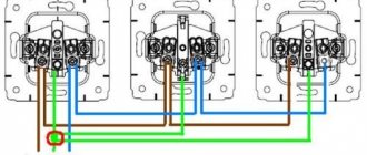
How to wire a socket from a distribution box? As a rule, the socket group runs on a separate line. In this case, everything is clear: you have three cables in the box, each with three (or two) conductors. In this case, usually brown is the phase wire, blue is neutral (neutral), and yellow-green is ground.
Wiring diagram for a socket in a distribution box
In another standard, the colors may be red, black and blue. In this case, the phase is red, blue is neutral, green is ground. In any case, the wires are collected by color: all of the same color in one group.
How to disconnect a junction box. The wires brought into the junction box are folded, stretched, and cut so that they are the same length. Do not cut short, leave a margin of at least 10 cm so that if necessary you can re-seal the connection. Then the conductors are connected using the chosen method.
If only two wires are used (in old houses there is no grounding), everything is exactly the same, only there are two connections: phase and neutral. By the way, if they are the same color, first find the phase (with a probe or multimeter) and mark it, at least by wrapping a piece of electrical tape around the insulation.
Connecting a single-key switch
If there is a switch, the matter is more complicated. There are also three groups, but their connection is different.
- Eat:
- input - from another junction box or from a panel;
- from the chandelier;
- from the switch.
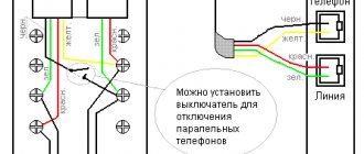
How should the circuit work? Power - “phase” - goes to the switch key. From its output it is fed to the chandelier. In this case, the chandelier will light only when the switch contacts are closed (the “on” position). This type of connection is shown in the photo below.
Connecting a single-key switch in a distribution box
If you look carefully, this is what happens: the phase with a light wire goes to the switch. It leaves from another contact, but this time blue (do not mix it up) and connects to the phase wire that goes to the chandelier. Neutral (blue) and ground (if network) are twisted directly.
Self-clamping terminals
It is even faster and easier to connect aluminum and copper conductors using self-clamping terminals.
The stripped conductors must be inserted into the terminal holes until they stop. There they will be automatically fixed with the help of pressure plates (it will firmly press the conductor to the tinned busbar). Thanks to the transparent housing of the terminal block, you can check whether the core has fully entered the terminal. The disadvantage of such devices is that they are disposable.
If you want a reusable clamp, use lever terminals. The lever rises and releases the entrance to the hole into which the stripped core must be inserted. After which the lever is lowered back, thereby fixing the conductor in the terminal. This connection is detachable; if necessary, the lever is raised and the wire is removed from the terminal.
Using such terminals is also extremely simple. The clamp itself indicates how long the insulating layer of the conductor needs to be stripped.
The advantages and disadvantages of using WAGO terminal blocks are described in this video:
Testing wire connections in junction boxes
After all connections have been made, the exposed sections of the conductors are insulated using heat-shrinkable tubing, and the wires are laid in junction boxes. The boxes themselves are left open until the installed electrical wiring is tested. First, voltage is supplied to the connected lines by turning on the corresponding circuit breakers.
If, after switching on, nothing sparked anywhere and the machine was not knocked out due to a short circuit due to an erroneous connection of wires or poor-quality insulation of connections, the electrical wiring is tested with load current (loading), which is carried out by connecting various electrical appliances to the mounted lines. It is recommended to load each line with the maximum permissible current.
The download should continue for some time (preferably several hours). During this period, possible electrical installation defects will have time to manifest themselves. A visual inspection of the connections in the junction boxes should be carried out - signs of high temperature will be visible by melting of the insulation or terminal blocks. It is also important that there is no characteristic odor of overheated or burnt insulation.
After relieving the voltage, you should check all connections by touch - they should not be hot. If, when loading electrical cables with the maximum rated current for several hours, no comments are identified regarding the operation of the connections, then the electrical installation is considered normal, the junction boxes can be closed and the wiring can be put into operation.
Author: Sergey Vladimirovich, electrical engineer. More about the author.
Where can I buy
You can resolve the issue as quickly as possible by visiting the nearest specialized store. The optimal option, in terms of price-quality ratio, remains purchasing from the AliExpress online store. Mandatory long waits for parcels from China are a thing of the past, because now many goods are in intermediate warehouses in destination countries: for example, when ordering, you can select the “Delivery from the Russian Federation” option:
| 3-pin waterproof distribution IP68 box | Distribution box, IP67 housing | Junction box, IP65 |
| 3-way distributor box, IP68 | Distribution box 2/3/4/5/6 way, IP68, 45A/450V | Mini junction box IP66, size 47*28*18mm |