The simplest memorization technique is mnemonic rules. They help to understand a complex action through simple representation or comparison. The article will give a detailed description of what the gimlet rule is and briefly and clearly describe its basic definition.
A description of the application of this rule to justify various physical laws will also be given. Additionally, a description of the left-hand rule and two mnemonic algorithms for determining the direction of electromagnetic induction will be given.
Definition
In a narrow sense, the gimlet rule is a mnemonic algorithm used to determine the spatial direction of magnetic induction, depending on the orientation of the electric current exciting the magnetic field.
This rule can be formulated as follows: If the tip of a gimlet (corkscrew, screw) is directed along the current vector, then the orientation of the magnetic induction lines will coincide with the direction towards which the handle of the gimlet rotates in the traditional version of this tool (with a right-handed screw)
Gimlet rule for a straight conductor
The figure shows a diagram for the simplest case: an electric current flows along a straight section of a conductor, away from the observer (blue arrow). The conditional corkscrew is directed with its sharp end along the line in the direction of the current. If we imagine the translational movement of a gimlet along a conductor, then the direction of the lines described by the handle of the corkscrew will coincide with the orientation of the magnetic lines of the electric field.
Interaction of currents
Let's consider two cases. The first is that current flows through a straight wire. The second is in a circular turn. As we know, current creates a magnetic field.
In the first case, the magnetic induction of a wire with current I at a distance R from it is calculated by the formula:
Mu is the magnetic permeability of a substance, mu with index zero is the magnetic constant.
In the second case, the magnetic induction in the center of a circular coil with current is equal to:
Also, when solving problems, the formula for the magnetic field inside the solenoid can be useful. A solenoid is a coil, that is, many circular turns with current.
Let their number be N , and the length of the solenoid itself be l . Then the field inside the solenoid is calculated by the formula:
By the way! For our readers there is now a 10% discount on any type of work
The main rule
The example we considered is a special case of the gimlet algorithm. There are several options for wording the rule, applicable in different situations.
The general or main formulation allows this rule to be extended to all cases. This is a variant of the mnemonic rule used to determine the orientation of the resulting vector product, called the axial vector, and also to select the right basis (three-dimensional coordinate system) associated with these vectors, which allows you to determine the sign of the axial vector.
Note: right basis is a convention according to which the Cartesian coordinate system (positive basis) is selected. Sometimes it is useful to use the mirror image of the Cartesian system (left or negative basis).
The main rule allows you to determine the direction in space of axial vectors important for calculations:
- angular velocity;
- induction current parameters;
- magnetic induction.
Although the orientation of the axial vector is arbitrary, it is important for calculations: by adhering to the accepted selection algorithm, it is easier to carry out calculations without the risk of confusing the signs.
In many cases, special formulations are used that well describe special cases in a specific situation.
Right hand rule
In electrical engineering, the interpretation of the gimlet for the right hand is often used.
The actions can be formulated as follows: “If the thumb of the right hand, set aside, is placed along the conductor so that it coincides with the direction of the electric current, then the remaining fingers will indicate the direction of the magnetic lines of force formed by the electric field. (see diagram in Fig. 2).
Right hand rule illustration
The algorithms formulated above are also applied to solenoids. But the difference is that in the case of a solenoid, the gimlet handle is rotated so that this movement coincides with the direction of the currents in the turns, and the advancement of the gimlet screw indicates the orientation of the vector of magnetic lines in the solenoid.
When using the right hand, fingers cover (conditionally) the coil so that the direction of the current in the turns coincides with the spatial arrangement of the fingers. Then the thumb will point to the orientation of the vector of electromagnetic lines inside the coil. Figure 3 shows diagrams explaining algorithms for determining the directions of vectors for solenoids.
Illustration of the right hand rule for a reel
It is not difficult to guess that these rules can be applied to determine the direction of the current. For example, if you use a magnetic needle to determine the direction of magnetic induction lines, then by applying the gimlet rule (as a variant of its formulation for the right hand), it is easy to determine in which direction the current flows.
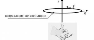
Gimlet's rule
Let's place several magnetic arrows next to the conductor and let a current flow through the conductor - the arrows will be oriented in the magnetic field of the conductor (Fig. 3.1, a). The north pole of each arrow will indicate the direction of the magnetic field induction vector at a given point, and therefore the direction of the magnetic lines of this field.
With a change in the direction of the current in the conductor, the orientation of the magnetic needles will also change (Fig. 3.1, b). This means that the direction of the magnetic lines depends on the direction of the current in the conductor.
Rice. 3.1. Determining the direction of the magnetic induction lines of the magnetic field of a current-carrying conductor using magnetic arrows
Determining the direction of magnetic induction lines using a magnetic needle is not always convenient, so the gimlet rule is used:
If you screw a gimlet in the direction of the current in the conductor, then the direction of rotation of the gimlet handle will indicate the direction of the magnetic lines of the magnetic field of the current (Fig. 3.2, a);
or else:
If you point the thumb of your right hand in the direction of the current in the conductor, then the four bent fingers will indicate the direction of the magnetic lines of the magnetic field of the current (Fig. 3.2, b).
Rice. 3.2. Determining the direction of the magnetic field lines of a current-carrying conductor using the gimlet rule
What determines the induction modulus of the magnetic field of a current-carrying conductor?
Remember: the magnetic effect of a current-carrying conductor was first discovered by X. Oersted in 1820. But why was this discovery not made earlier? The fact is that with increasing distance from the conductor, the magnetic induction of the field created by it quickly decreases. Therefore, if the magnetic needle is not located near the current-carrying conductor, the magnetic effect of the current is almost imperceptible.
Rice. 3.3. Magnetic induction lines of the magnetic field of a straight conductor carrying current. The conductor is located perpendicular to the plane of the pattern; The cross means that the current in the conductor is directed away from us
Magnetic induction also depends on the strength of the current: with increasing current in the conductor, the magnetic induction of the magnetic field created by it increases.
What is the gimlet rule?
Gimlet - a tool for drilling holes
It sounds like this: in cases where the direction of the gimlet coincides with the direction of the current in the conductor during translational movements, then at the same time the direction of rotation of the handle of the gimlet will be identical to it.
Determination of magnetic field
When studying electrical phenomena in 8th grade, you learned that in the space around a charged body there is a field called electric, and that it is through this field that electrical interaction between charged bodies and particles occurs.
There is also a field near a magnetized body and near a conductor carrying current - it is called magnetic. Magnetic interaction occurs at a certain speed through a magnetic field (the first to come to this conclusion was the English physicist Michael Faraday (1791-1867)).
Coils carrying current behave like permanent magnets
Let's consider the interaction of a permanent magnet and a coil with current. A coil with current creates a magnetic field. The magnetic field spreads in space and begins to act on a permanent magnet (magnetized body) - the magnet is deflected. The magnet also creates its own magnetic field, which, in turn, acts on the current-carrying coil, and the coil also deflects.
Note that a magnetic field also exists near any moving charged particle and near any moving charged body and acts with some force on charged bodies and particles moving in this magnetic field.
Please note: we cannot see the magnetic field, but at the same time it, like the electric field, is absolutely real - it is a form of matter.
A magnetic field is a form of matter that exists near magnetized bodies, current-carrying conductors, moving charged bodies and particles and acts on other magnetized bodies, current-carrying conductors, moving charged bodies and particles located in this field.
It will be interesting➡ TL431: diagram, characteristics, datasheet and analogues. Schemes and principles of operation of the TL431 stabilizer
Let's summarize:
Bodies that retain their magnetic properties for a long time are called permanent magnets. The main properties of permanent magnets: 1) the magnetic effect of a magnet is most pronounced near its poles; 2) like poles of magnets repel, unlike poles attract; it is impossible to obtain a magnet with only one pole; 3) when a permanent magnet is heated to a certain temperature (Curie point), its magnetic properties disappear.
Magnetic interaction is carried out through a magnetic field. A magnetic field is a form of matter that exists near magnetized bodies, current-carrying conductors, moving charged bodies and particles and acts on magnetized bodies, current-carrying conductors, moving charged bodies and particles located in this field.
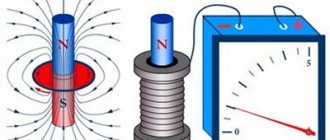
We cannot see the magnetic field, but to better understand magnetic phenomena it is important to learn how to depict it. Magnetic needles will help with this. Each such arrow is a small permanent magnet that easily rotates in the horizontal plane. You will learn from this paragraph how the magnetic field is graphically depicted and what physical quantity characterizes it.
A magnetic needle is a permanent magnet. The dotted line shows the axis of the magnetic needle
If a charged particle moves in a magnetic field, then the field will act on the particle with some force. The magnitude of this force depends on the charge of the particle, the direction and speed of its movement, and also on how strong the field is.
The strength characteristic of a magnetic field is magnetic induction.
Magnetic induction (magnetic field induction) is a vector physical quantity that characterizes the force action of a magnetic field.
Magnetic induction is indicated by the symbol
The SI unit of magnetic induction is tesla; named after the Serbian physicist Nikola Tesla (1856-1943):
In a magnetic field, magnetic arrows are oriented in a certain way: the north pole of the arrow indicates the direction of the magnetic field induction vector at a given point
The direction of the magnetic induction vector at a given point of the magnetic field is taken to be the direction indicated by the north pole of the magnetic needle installed at this point
Note! The direction of the force with which the magnetic field acts on moving charged particles or on a current-carrying conductor, or on a magnetic needle, does not coincide with the direction of the magnetic induction vector. How to express 1 Tesla through other SI units, what formula can be used to determine the magnetic induction module, and the direction of the force with which the magnetic field acts on a current-carrying conductor.
Magnetic lines:
- outside the magnet they leave the north pole of the magnet and enter the south pole;
- always closed (the magnetic field is a vortex field);
- most densely located at the poles of the magnet;
- never intersect
In Fig. We see how magnetic needles are oriented in a magnetic field: their axes seem to form lines, and the magnetic induction vector at each point is directed along the tangent to the line passing through this point.
Conditional directed lines, at each point of which the tangent coincides with the line along which the magnetic induction vector is directed, are called magnetic induction lines or magnetic lines.
Magnetic fields are graphically depicted using magnetic lines:
- the direction of the magnetic induction line at a given point is taken to be the direction of the magnetic induction vector;
- The larger the magnetic induction module, the closer the magnetic lines are drawn to each other.
Having examined the graphical representation of the magnetic field of a strip magnet, we can draw some conclusions. Note that these conclusions are valid for the magnetic lines of any magnet.
The pattern of magnetic lines can be reproduced using iron filings. Let's take a horseshoe magnet, put a plexiglass plate on it and pour iron filings onto the plate through a strainer. In a magnetic field, each piece of iron will be magnetized and turn into a small “magnetic needle”. Improvised “arrows” are oriented along the magnetic lines of the magnet’s magnetic field (Fig. 2.4).
Chains of iron filings reproduce the pattern of magnetic induction lines of the magnetic field of a horseshoe magnet
A magnetic field in a certain part of space is called uniform if at each point the magnetic induction vectors are the same both in magnitude and in direction
The magnetic field inside a strip magnet (a) and between two magnets facing each other with opposite poles can be considered uniform
In areas where the magnetic field is uniform, the lines of magnetic induction are parallel and located at the same distance from each other. Magnetic lines of a uniform magnetic field directed towards us are usually depicted as dots - it’s as if we see “arrowheads” flying towards us. If magnetic lines are directed away from us, then they are depicted with crosses - it’s as if we see the “feathers of arrows” flying from us
In most cases, we are dealing with a non-uniform magnetic field - a field at different points of which the magnetic induction vectors have different values and directions. The magnetic lines of such a field are curved, and their density is different.
Image of magnetic induction lines of a uniform magnetic field, which are perpendicular to the plane of the drawing and directed towards us (a); directed from us (b)
To study terrestrial magnetism, William Gilbert made a permanent magnet in the form of a ball (model of the Earth). Having placed a compass on the ball, he noticed that the compass needle behaves in the same way as on the surface of the Earth.
Experiments allowed the scientist to suggest that the Earth is a huge magnet, and its south magnetic pole is located in the north of our planet. Further research confirmed W. Gilbert's hypothesis.
In Fig. shows a picture of the magnetic induction lines of the Earth's magnetic field.
It will be interesting➡ Electricity - how it is produced and what it consists of. What is electric current?
Layout of magnetic lines of the magnetic field of planet Earth
The magnetic induction lines of the Earth's magnetic field are not parallel to its surface. If you fix the magnetic needle in a gimbal, that is, so that it can rotate freely around both the horizontal and vertical axes, the needle will be installed at an angle to the surface of the Earth
Magnetic needle in gimbal
The Earth's magnetic field has long helped travelers, sailors, military personnel and others to navigate. It has been proven that fish, marine mammals and birds orient themselves according to the Earth’s magnetic field during their migrations. Some animals, such as cats, also navigate when looking for the way home.
Studies have shown that in any area the Earth's magnetic field changes periodically, every day. In addition, small annual changes in the Earth's magnetic field are observed. However, there are also sudden changes. Strong disturbances in the Earth's magnetic field, which cover the entire planet and last from one to several days, are called magnetic storms. Healthy people practically do not feel them, but for those who have cardiovascular diseases and diseases of the nervous system, magnetic storms cause a deterioration in their well-being.
The Earth's magnetic field is a kind of “shield” that protects our planet from charged particles flying from space, mainly from the Sun (“solar wind”). Near the magnetic poles, streams of particles fly quite close to the Earth's atmosphere. As solar activity increases, cosmic particles enter the upper layers of the atmosphere and ionize gas molecules - auroras are observed on Earth
As solar activity increases, the area of dark spots on the Sun increases (a), and magnetic storms and auroras occur on Earth (b)
Let's summarize:
Magnetic induction is a vector physical quantity that characterizes the force action of a magnetic field. The direction of the magnetic induction vector coincides with the direction to which the north pole of the magnetic needle points. The SI unit of magnetic induction is tesla (T).
Conditional directed lines, at each point of which the tangent coincides with the line along which the magnetic induction vector is directed, are called magnetic induction lines or magnetic lines.
Magnetic induction lines are always closed, outside the magnet they leave the north pole of the magnet and enter the south pole, and are denser in those areas of the magnetic field where the magnetic induction module is greater.
Planet Earth has a magnetic field. Near the Earth's north geographic pole is its south magnetic pole, and near its south geographic pole is its north magnetic pole.
You already know that there is a magnetic field near a current-carrying conductor. Let's study the magnetic field of a straight conductor carrying current. To do this, we pass the conductor through a sheet of cardboard (perpendicular to the sheet), sprinkle iron filings on the cardboard and close the circuit. In the magnetic field of the conductor, the sawdust will be magnetized and recreate the picture of the magnetic induction lines of the magnetic field of a straight conductor with current - concentric circles surrounding the conductor. How to determine the direction of magnetic lines?
Magnetic flux and emf
If magnetic induction is a vector characteristic of a magnetic field, then magnetic flux is a scalar quantity, which is also one of the most important characteristics of the field. Let's imagine that we have some kind of frame or contour that has a certain area. Magnetic flux shows how many lines of force pass through a unit area, that is, it characterizes the intensity of the field. It is measured in Webers (Wb) and denoted F.
S – contour area, alpha ( perpendicular) to the contour plane and vector B.
When the magnetic flux through a loop changes, an emf equal to the rate of change of the magnetic flux through the loop. By the way, you can read more about what electromotive force is in another of our articles.
Essentially, the formula above is the formula for Faraday's law of electromagnetic induction. We remind you that the rate of change of any quantity is nothing more than its derivative with respect to time.
The opposite is also true for magnetic flux and induced emf. A change in current in the circuit leads to a change in the magnetic field and, accordingly, a change in the magnetic flux. In this case, a self-induction EMF arises, which prevents a change in the current in the circuit. The magnetic flux that penetrates the current-carrying circuit is called its own magnetic flux, is proportional to the current strength in the circuit and is calculated by the formula:
L is a proportionality coefficient called inductance, which is measured in Henry (H) . The inductance is affected by the shape of the circuit and the properties of the medium. For a coil with length l and number of turns N, the inductance is calculated by the formula:
Formula for self-induced emf:
Looking for direction
To figure it out, you still have to remember your school lessons. At them, physics teachers told us that electric current is the movement of elementary particles, which at the same time carry their charge along a conductive material. Thanks to the source, the movement of particles in the conductor is directed. Movement, as we know, is life, and therefore nothing more than a magnetic field arises around the conductor, and it also rotates. But how?
The answer is given by this very rule (without using any special tools), and the result turns out to be very valuable, because depending on the direction of the magnetic field, a couple of conductors begin to act according to completely different scenarios: either repel each other, or, on the contrary, rush towards each other.
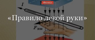
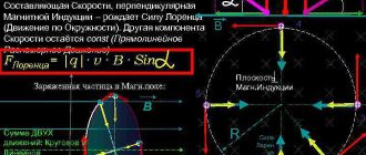
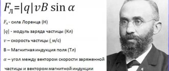
Lorentz force
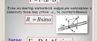
The left-hand rule allows you to display the direction of the Lorentz force. This parameter determines the magnitude of the impact of the magnetic field on charged particles in the conductor. Using simple words, this physical phenomenon can be interpreted as follows: moving charged particles are affected by magnetic induction. The direction of action of these forces is strictly perpendicular to the direction of particle motion.
Using your left hand, you can visually determine the direction of influence of the magnetic induction lines. This is done as follows:
- The left palm is straightened, with the thumb at a 90-degree angle. The palm is a conductor, which is perpendicularly affected by the forces of electromagnetic induction (vector B).
- The thumb points to the direction of the Lorentz force (vector Fl).
- 4 straightened fingers indicate the direction of the positive charge. Provided that a negative charge flows through the conductor, the direction of movement will be towards the palm, and not away from it. This condition is very important in calculations.
The Lorentz force is calculated using the following formula:
In this formula:
- Fl - Lorentz force;
- q is the amount of charge;
- v is the speed of charge movement;
- B—magnetic induction;
- a is the angle between the direction of particle motion and magnetic induction.
The calculation takes into account the parameter of particles that flow through the conductor. Also, the direction of particle movement is taken into account.
Formulation of the gimlet rule
Peter Buravchik is the first physicist to formulate the left-hand rule for various particles and fields. It is applicable both in electrical engineering (helps determine the direction of magnetic fields) and in other fields. It will help, for example, determine the angular velocity.
A simple and clear explanation with a clear example
The gimlet rule (right hand rule) - this name is not related to the name of the physicist who formulated it. The name is more based on a tool that has a certain direction of the screw. Usually a gimlet (screw, corkscrew) has a so-called The thread is right-handed, the drill enters the ground clockwise. Let's consider the application of this statement to determine the magnetic field.
The main thing is not to forget in which direction the current flows
You need to clench your right hand into a fist, raising your thumb up. Now let's loosen the other four a little. They are the ones who tell us the direction of the magnetic field. In short, the gimlet rule has the following meaning - by screwing the gimlet along the direction of the current, we will see that the handle rotates in the direction of the line of the magnetic induction vector.
Explanation of the name
Most people remember mention of this from a physics course, namely the electrodynamics section. This happened for a reason, because this mnemonic is often given to students to simplify their understanding of the material. In fact, the gimlet rule is used both in electricity, to determine the direction of the magnetic field, and in other sections, for example, to determine angular velocity.
A gimlet is a tool for drilling small-diameter holes in soft materials; for a modern person, it would be more common to use a corkscrew as an example.
Important! It is assumed that the gimlet, screw or corkscrew has a right-hand thread, that is, the direction of its rotation when tightened is clockwise, i.e. to the right.
The video below provides the full formulation of the gimlet rule, be sure to watch it to understand the whole point:
How is the magnetic field related to the gimlet and hands?
In physics problems, when studying electrical quantities, one is often faced with the need to find the direction of the current from the magnetic induction vector and vice versa. These skills will also be required when solving complex problems and calculations involving magnetic field systems.
Before we begin to consider the rules, I want to remind you that current flows from a point with a higher potential to a point with a lower one. To put it simply, current flows from plus to minus.
It will be interesting➡ Twisted pair: categories, crimping, work tips
Magnetism: Definition
Magnetism is the interaction of moving electric charges through a magnetic field.
A field is a special form of matter. Within the standard model, there are electric, magnetic, electromagnetic fields, a nuclear force field, a gravitational field and the Higgs field. Perhaps there are other hypothetical fields that we can only guess about or not guess at all. Today we are interested in the magnetic field.
The right and left hand rule: application in practice
Considering the application of this law, let's start with the right-hand rule. If the direction of the magnetic field vector is known, using a gimlet you can do without knowing the law of electromagnetic induction. Let's imagine that the screw moves along the magnetic field. Then the direction of current flow will be “along the thread,” that is, to the right.
Another clear and understandable explanation
Applying the Right Hand Rule to a Solenoid
Let us pay attention to a permanent controlled magnet, an analogue of which is a solenoid. At its core, it is a coil with two contacts. It is known that current moves from “+” to “-”. Based on this information, we take the solenoid in our right hand in such a position that 4 fingers indicate the direction of current flow. Then the extended thumb will indicate the vector of the magnetic field.
Applying the Right Hand Rule to a Solenoid
Basis
Basis - several vectors located in space. In this case, the basis vectors represent an ordered set. Under this condition, any of the vectors can be represented once as a linear combination of all vectors from this set. The basis mnemonic algorithm is as follows: the gimlet is twisted to the right, while the X basis moves along a short path to the Y basis, and therefore towards the Z basis.
For the right hand rule it would look like this:
- The middle finger is the X base. It moves towards the index finger or Y base.
- With this movement, the direction is right-handed, which means it is directed towards the Z base.
For bases, you can also use the clock dial rule, but only with the use of three hands and when the direction of rotation is to the right. Left orientation is taken into account only under a specifically stated condition.
Determining the direction of current with a gimlet
If you know the direction of vector B - magnetic induction, you can easily apply this rule. Mentally move the gimlet along the direction of the field in the coil with the sharp part forward, respectively, clockwise rotation along the axis of movement will show where the current flows.
If the conductor is straight, rotate the corkscrew handle along the indicated vector, so that this movement is clockwise. Knowing that it has a right-hand thread - the direction in which it is screwed in coincides with the current.
Moment of power
The gimlet rule is applicable to determine the moment of force. The moment of force is calculated using the following formula:
The following quantities are used in this expression:
- M is the moment of force;
- ri is a vector or radius applied to point i.
- Fi is the force applied to point i.
The rule for a gimlet applied to the moment of force is interpreted as follows: if the gimlet is screwed in the direction in which the forces are trying to rotate the body, it will screw in precisely in the direction of the moment of the acting forces. For example, when screwing a screw, it will be screwed in the direction of rotation of the screwdriver handle, since this direction is created by the force of the movement of the person’s hand.
The moment of force can be determined visually. The version of the right hand rule used in this case will be as follows: if you take an object in your right hand, squeeze it and put your thumb forward, then 4 fingers will point to the direction of the circular motion of the body, and the thumb to the direction of the moment of force.
Useful information and tips
- It is generally accepted that the direction of current points from plus to minus. In fact, in a conductor, the orderly movement of electrons is directed from the negative pole to the positive pole. Therefore, if you were faced with the task of calculating the Lorentz force for an individual electron in a conductor, you should take this circumstance into account.
- By default, we consider a screw (gimlet, corkscrew) with a right-hand thread. However, we should not forget about the existence of screws with left-hand threads.
- When using the clockwise rule, we assume that the arrows move from left to right. It is known that in the former USSR watches with a reverse movement of the clock mechanism were produced. Perhaps such models exist to this day.
Tips: if you need to determine the spatial location of the moment of force under the influence of which a certain body rotates, rotate the screw in the same direction. The conditional insertion of the screw will indicate the orientation of the force moment vector. The speed of rotation of the body does not affect the direction of the vector.
It is useful to know that when the gimlet rotates along the direction of rotation of the body, the trajectory of its screwing in will coincide with the direction of the angular velocity.
Faraday's law of electromagnetic induction
Law of electromagnetic induction (Faraday's law):
The induced emf in a closed loop is equal and opposite in sign to the rate of change of the magnetic flux through the surface bounded by the loop:
The “–” sign in the formula allows you to take into account the direction of the induction current. The induced current in a closed circuit always has such a direction that the magnetic flux of the field created by this current through the surface bounded by the circuit would reduce those changes in the field that caused the appearance of the induced current.
If the circuit consists of \( N \) turns, then the induced emf:
The strength of the induction current in a closed conductive circuit with resistance \( R \):
When a conductor of length \( l \) moves with a speed \( v \) in a constant uniform magnetic field with induction \( \vec{B} \) the emf of electromagnetic induction is equal to:
where \( \alpha \) is the angle between the vectors \( \vec{B} \) and \( \vec{v} \).
The occurrence of induced emf in a conductor moving in a magnetic field is explained by the action of the Lorentz force on free charges in moving conductors. The Lorentz force plays the role of an external force in this case.
A conductor moving in a magnetic field through which an induced current flows experiences magnetic braking. The total work done by the Lorentz force is zero.
The amount of heat in the circuit is released either due to the work of an external force, which maintains the speed of the conductor unchanged, or due to a decrease in the kinetic energy of the conductor.
Important! A change in the magnetic flux penetrating a closed circuit can occur for two reasons:
- the magnetic flux changes due to the movement of the circuit or its parts in a time-constant magnetic field. This is the case when conductors, and with them free charge carriers, move in a magnetic field;
- The second reason for the change in the magnetic flux penetrating the circuit is the change in time of the magnetic field when the circuit is stationary. In this case, the occurrence of induced emf can no longer be explained by the action of the Lorentz force. The phenomenon of electromagnetic induction in stationary conductors, which occurs when the surrounding magnetic field changes, is also described by Faraday's formula.
Thus, the phenomena of induction in moving and stationary conductors proceed in the same way, but the physical reason for the occurrence of induction current turns out to be different in these two cases:
- in the case of moving conductors, the induced emf is due to the Lorentz force;
- in the case of stationary conductors, the induced emf is a consequence of the action on free charges of the vortex electric field that occurs when the magnetic field changes.
Notes
- For mathematical details of the general concept of basis orientation discussed here, see the article Orientation.
- By determining the direction here, we mean the choice of one of two opposite directions (the choice between just two opposite vectors), that is, it comes down to the choice of the positive direction.
- This means that other rules may also be convenient in any number, but their use is not necessary.
- This means that you can use the opposite rule if you wish, and sometimes this can even be convenient.
- The concept of a right and left basis extends not only to orthonormal bases, but to any three-dimensional bases (that is, to oblique Cartesian coordinates too), however, for simplicity, we will limit ourselves here to the case of orthonormal bases (rectangular Cartesian coordinates with equal scales along the axes).
- You can verify that in general this is indeed the case, based on the elementary definition of a vector product: A vector product is a vector perpendicular to both factor vectors, and in magnitude (length) equal to the area of the parallelogram. The same thing, which of two possible vectors perpendicular to two given ones should be chosen is the subject of the main text; the rule that allows this to be done and complements the definition given here is indicated there.
- Left-hand threads are used in modern technology only when the use of right-hand threads would lead to the danger of spontaneous unscrewing under the influence of constant rotation of the part in one direction - for example, left-hand threads are used at the left end of the bicycle wheel axle. In addition, left-hand threads are used in reducers and cylinders for flammable gases to eliminate the connection of a flammable gas reducer to the oxygen cylinder.
- In addition, in their cases, they can be more convenient than the general rule, and are even sometimes formulated organically enough to be especially easy to remember; which, however, apparently still does not make memorizing them all any easier than memorizing just one general rule.
- Even if we are dealing with a fairly asymmetrical (and asymmetrically located relative to the axis of rotation) body, so that the coefficient of proportionality between the angular velocity and angular momentum is the inertia tensor, which is not reducible to a numerical coefficient, and the angular momentum vector is then generally speaking not parallel to the angular velocity vector, however, the rule works in the sense that the direction is given approximately, but it is enough to make a choice between two opposite directions.
- Strictly speaking, with this comparison there is also a constant coefficient of 2, but in this topic this is not important, since we are now talking only about the direction of the vector, and not about its magnitude.
- Not a mandatory requirement.
Next
MiscellaneousWhat is active power?
Left and right coordinate system
Vector rectangular coordinate indicators are taken to calculate the state of various segments. In this case, the ordinate and abscissa of the targeted beam correspond to the initial position of the point and coincide with the final characteristics.
If the initial and final coordinates of the vectors do not match, then do the following:
- transfer of a directed segment so that its beginning coincides with the origin of the coordinate region;
- subtracting the ordinate and abscissa values of the edge of a segment from the system indicators of the beginning of the ray instead of moving the starting point.
In accordance with the gimlet rule, finding a segment on the coordinate plane corresponds to a vector stereo projection onto the main rod and allows you to use the right hand pattern. The measurement tasks are tacitly specified in each individual case. These patterns relate to conventional concepts, but the vector combination is selected taking into account the same scale of the Cartesian plane in the direction of any axes.
In this case, you need to follow certain rules:
- a left-ordered vector set is used if using a right-sided cluster is not possible;
- the left and right vector sets are congruent in mirror vision.
The rules are applied to calculate the path of the vector product and the laws of constructing rays in the plus direction. This method of determination makes sense with a direct current conductor. The principle does not work in relation to the class of induction coils, when the current guide represents the windings of the structure and is not straight.
Vector artwork
The result is determined by the principle of the gimlet and the right palm, when the segments are displayed with the same sources, and the rotation of the first ray follows a short path to the next vector. In this case, the screw is turned along the path following the base of the result of vector multiplication. In the form of a gimlet, hardware with a right-hand spiral cut is used.
If, when placing the conductor in the right hand, the fingers are folded onto the rod, then they determine the path of the spirals, and the thumb shows the direction of the basis product. Sometimes the rays coincide with the sources at a certain point. In this case, the thumb shows the course of the first segment (participant in the work), the index finger is located along the second ray, and the middle finger, according to the pattern of the gimlet, will determine the direction of the result from the multiplication of vectors.
Rays and spatial indicators
The vector interaction of two beams in a three-dimensional region is determined by the section of the beam that is in a perpendicular position to their initial modules. The length of the vector product is calculated as the area of a rectangle or parallelogram located between the original segments. The course of the rays is taken so that the first 3 resulting vectors are located on the right. If one of them has a zero exponent, then the result of the multiplication tends to zero.
The gimlet rule or the patterns of the left and right hands do not apply to mandatory standards for the operation of electrical equipment. Sometimes the characteristics of magnetic space are determined using vector ratio formulas. You should know the following:
- The gimlet's law involves turning the screw and the beam so that the first vector tends to merge with the second along the shortest path: the direction of the screw will show the path of the third right basis.
- According to the principle of the right palm, with parallel arrangement of sections along the lines, the thumb is located along the right ray (X), the index finger lies along the course of the second segment (Z). The middle finger will indicate the position of the third vector along the (Y) axis, and the union of the vectors will be located to the right of the central axis.
To use the gimlet rule, the observer must have a little imagination to mentally draw the turns and place the fingers correctly.
Finding electromotive force
EMF occurs when a conductor crosses an electromagnetic field or in the event of transformation of the properties of potential space. Force is measured by the rate of change of magnetic current. Increasing or decreasing the current reforms the generated flux, which interacts with neighboring conductors.
The direction of the induced emf is determined by the right palm rule. The hand with the conductor is placed so that the potential lines enter the hand, and the outstretched finger determines the direction of the wire. Straightened 4 fingers will indicate the path of current flow in a closed circuit.
If the gimlet is turned along the course of the spatial vortex at the point where the vectors arise, then its translational movement will indicate the path of rotation of the engine rotor. This can be seen if four fingers of the right hand are squeezed in the direction of the vortex. A bent finger will show the desired path.