In order to independently install and connect various types of electrical equipment: lamps, sockets, automatic machines, electric stoves, boilers and others, you need to understand the designation of phase and zero for switching: L (phase), N (zero), PE (grounding). State standards and electrical safety regulations establish designation rules, which simplifies the determination of the functional purpose of the cores during installation so that the connected device can function correctly.
What does the "L" on the switch mean?
This coding came to the field of electrical installation activities from English. It is based on the initial letter of the noun “Line”, which is translated as “line”. This is the established name for electrical wiring containing a phase. You can also look in the technical dictionary of English names, where “Lead” is the supply wire or “Live” is under 220 V (voltage).
The symbol “L” on the switch is applied to the connecting elements (contacts and clamps) intended for connecting a conductor with a phase. In a network with a voltage of 380 V (3-phase), letters and numbers are used for marking to identify wires:
- L1;
- L2;
- L3.
The L designation on the switch is not the only coding option for the product. Different manufacturers rarely use the same symbols in production.
Operating principle of a single-key switching element
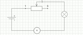
Let's give a specific example to clarify the operating principle. The switching device is installed with a break in the conductor having a voltage of 220 V and connected to the lamp. There are 2 wires for such a switch in a single-phase electrical network.
Operating principle of a single-key switch Source samelectrik.ru
The first of them, codenamed “A,” connects the power panel to the switch and transports electric current through it. This wiring is always under electrical voltage of 220 Volts. Other wiring runs from the switching element to the light source and delivers current to it. When you press the switch, both contacts are connected to each other. Voltage is supplied to the lighting fixture and the lamps immediately light up. Returning the switch to its original position breaks the circuit connection, the contact disappears, so the lamp goes out due to the lack of current in it.
The coding “L” on the switch indicates a terminal designed to connect a conductor that has a phase. In our case, according to the diagram, this is cable “A” stretched from the electrical panel. Such wiring is constantly under high voltage.
Coloring in DC networks
For DC networks, it is customary to mark conductors connected to the positive pole in red, and to the negative pole in black or blue. In bipolar circuits, blue insulation is used to mark the midpoint (zero) of the power supply.
There are no standards for color codes on multi-voltage circuits. What color are the plus and minus wires, what voltage is in them - this can only be determined by the decoding of the device manufacturer, which is often given in the documentation or on one of the walls of the structure.
Example: computer power supply or car wiring.
Automotive wiring is characterized by the fact that in it the circuits with positive voltage of the on-board network are red or its shades (pink, orange), and those connected to ground are black. The remaining wires have a specific color, which is determined by the car manufacturer.
How to determine phase wiring?
To understand which conductor needs to be connected to the “L” terminal on a single-key switch, it is recommended to use an indicator screwdriver specially designed for this purpose. If, when checking, a light comes on on any of the wires, then there is voltage on it. This wire is conductive - cable “A”.
In the other, unoccupied clamp of the single-key switching element, cable “B” is connected, stretched directly to the switch. It is usually labeled differently:
- «1»;
- "L1";
- «->»;
- just an arrow, or not marked at all.
Designation of contacts of a single-key switch Source odstroy.ru
In the case when, when examining the terminals, in addition to the “L” symbol, other connections are found on the switch, also containing other designations, this means that 2- or 3-key elements have been encountered.
Installing a cable responsible for turning on a specific lighting fixture
It is almost impossible to determine this without an electrician’s tool. In practice, such a connection is usually established experimentally. For this purpose, the unoccupied ends with the current conductor in the terminal are checked one by one using a voltage indicator. In this way you can see which lamps light up.
The switching element can be connected to the network arbitrarily, with the exception of the “L” terminal. In the case when it turns out that the terminals are accidentally confused, you need to swap the wiring L2 and L3 in the 2-key device.
When there are 3 or 4 terminals for connecting to the network, and the element is single-key, then you have encountered a type of switching device.
Type of connections for connecting lamps Source asutpp.ru
Specifics of connecting a single-phase switching device to the network
To understand the specifics of connecting a standard version of a switching device, you need to know the principle of its operation. This was mentioned in the article a little earlier.
Connection features:
- The light switch is always installed with a break in the current-carrying conductor.
The 2nd end of the wiring is laid to the distribution box (distribution box) or directly connected to the lighting fixture.
- There are only 2 cables on both sides of the terminal.
Each of these 2 wires has its own purpose. The first connects a single-phase circuit breaker located in the switchboard to the switch. This wire is always under (220 V) voltage. The other conductor has no current, since it is a neutral wiring. If you connect this wire to a lamp, the lamp will not light up, since there is no voltage in it.
When the key is moved to the “On” position, 220 V is supplied to the single-phase switch (depending on the model of the element). After this, the working lighting device or lamp lights up.
Features of connecting a single-phase switch Source extremale.ru
Color codes for phase L, neutral N and ground
For ease of installation, any electrical cable is made with multi-colored insulation on the cores. When installing standard electrical wiring, three-core cables are usually used (phase, neutral, ground).
For ease of installation, any electrical cable is made with multi-colored insulation on the cores. When installing standard electrical wiring, three-core cables are usually used (phase, neutral, ground).
Phase (“L”, “Line”)
The main wire in the cable is always the phase. The word "phase" itself means "live wire", "active wire" and "line". Most often it comes in strictly defined colors. In the distribution panel, the phase wire, before going to the consumer, is connected through a residual current device (RCD, fuse), and phase switching occurs in it. Attention! There are no jokes with the bare phase, so in order not to confuse the phase with anything else, remember: the phase contacts are always marked with the Latin symbol “L”, and the phase wire can be red, brown, white or black . If you are not sure about this or the wiring is arranged differently, then purchase a screwdriver with a simple phase indicator. By touching its tip to the bare conductor, you can always find out whether it is a phase or not by the characteristic glow of the indicator. It’s better to immediately contact a qualified specialist.
Zero (“N”, “Neutre”, “Neutral”, “Neutral” “Zero”)
The second important wire is zero, popularly known as “wire without current”, “passive wire” and “neutral”. It only comes in blue . In apartment distribution panels it must be connected to the zero bus, it is marked with the symbol “N”. To the socket, the zero wire is connected to the contacts, also marked with the sign “N”.
Grounding (“G”, “T”, “Terre”, “Ground”, “gnd” and “Earth”)
The insulation of the ground wire is only yellow with a green stripe. In the distribution panel it is connected to the grounding bus, to the door and body of the panel. In sockets, grounding is connected to contacts marked with the Latin symbol “G” or with a sign in the form of an inverted and briefly underlined letter “T”. Typically, grounding contacts are visible and can protrude from sockets, becoming accessible to children, which sometimes causes shock to many parents; however, these contacts are not dangerous, although sticking your fingers there is still not recommended.
Attention! When working with live electrical networks, there is always a high probability of electric shock or fire. Even if an RCD is installed, it is strongly recommended to follow all safety precautions! It is known that the special design of such a switch checks the synchronism of the phase and zero operation, and if the RCD detects a phase current leak without returning some of its percent to zero, it will immediately break the contact, which will save a person’s life; however, if you touch not only the phase, but also zero, then the RCD will not save you. Touching both wires is deadly.
Sources:
The question of how to connect a two-key light seems to be a huge problem for many. There are no problems with a single-key switch, everything is clear and easy, but here many people have difficulties. In fact, the wolf is not as scary as it is portrayed. Connecting a two-button light is as easy as hammering a nail into a wall. In this article we will look in detail at an example of such a connection. For the best perception of information and clarity of the example, we will use detailed comments supplemented with thematic photographs.
Before moving on to connecting a double switch, you need to have at least a superficial understanding of the structure of its mechanism, the purpose of the terminals and contacts on it, and if you wish, you can also inquire about the connection diagram of a two-key switch.
Other markings on the switching element
In addition to the “L” designation on the switch, other codes and symbols can be found on the contact connection of the lighting element or the lamp body. Switching device manufacturers often use the character encoding principle. It is based on 2 switch positions: on and off.
For marking with symbols, “0” and “1” are used. The zero position of the switch is the “OFF” or “OFF” position. Typically the key is located at the bottom of the switching device housing. The second position means "ON" or "On" (ON). Typically applied to the top of the switch. Sometimes there are rare symbols in the form of an arrow “->”, which indicates the direction of commutation.
Other designations on a single-phase switch Source uzotoka.ru
After familiarizing yourself with all the symbols, in addition to “L”, indicated on single-key room lighting switches, anyone can independently connect the switching element to the electrical network. If necessary, it will be possible to repair the faulty device. Knowledge of the markings applied to switches produced by various manufacturers will help with this.
Neutral conductors
These electrical wires are divided into three categories:
- zero working conductors.
- neutral protective (ground) conductors.
- neutral conductors, combining protective and working functions.
What is the designation of wires in electrics L and N? The network neutral or neutral working conductor in electrical circuit diagrams is designated by the Latin letter “N”. The neutral conductors of the cables are colored as follows:
- blue color throughout its entire length without additional inclusions;
- blue color along the entire length of the core without additional inclusions.
What do L, N and PE mean in electrical engineering? PE (N-RE) is a neutral protective conductor, which is painted with alternating lines of yellow and green along the entire length of the wire entering the cable.
The third category of neutral conductors (REN-wires), which combine working and protective functions, have a color designation in electrical engineering (L and N). The wires are painted blue, with ends and connections with yellow-green stripes.
Illuminated switches
Such switching devices allow you to keep your walls clean. Quite often you have to turn on the light at night when everything is dark. When you try to feel the switch key in the dark, your hand often hits the wall instead of the key and gets dirty. As a result, abrasions form on the wall surface around the switching device.
Since the price difference is negligible, using an illuminated switch becomes a priority. However, many buyers still choose classic models. Why is this happening?
This situation arises due to the fact that various rumors and “legends” about the negative aspects of backlighting are spread via the Internet:
- Such types of switching elements consume electricity in greater quantities than established by regulations.
Some of this information can be considered reliable. When connecting backlit switches to an electrical network, the illuminated element consumes approximately 1 W of energy. By the end of a full month, this figure becomes equal to 0.5-0.7 kW/hour. Therefore, 3-5 rubles. You will need to pay for the convenience and comfort of connected lighting.
Today, this horror story is losing its relevance over time due to the insignificance of additional costs.
Wire classification
The conductor consists of one uninsulated or one or more insulated conductors. The second type of conductors is covered with a special non-metallic sheath. This can be a winding with insulating tape or a braid made of fibrous raw materials. Bare wires do not have any protective coatings. They are used in the construction of power lines.
Based on the above, we conclude that the wires are:
- protected;
- unprotected;
- power;
- installation.
They must be used strictly for their intended purpose. The slightest deviation from operating requirements leads to a breakdown of the power supply network. As a result of the short circuit, fires occur.
Connecting a single-key switching device equipped with backlight
The specific feature of the operation of such devices is based on Ohm's laws. It is formed on the principle that when lines are connected in parallel, and the incoming wires have unequal cross-sections, after voltage is applied to the cable line, electric current will flow through the conductor having the least resistance.
Depends on the selected lighting source: to connect an LED lamp or neon lamp, you need to choose a connection scheme that is characterized by increased resistance. This line specificity is created by a limiting resistor.
Turning off the backlight in a single-phase switch Source evrikann.ru
When the switching device is disconnected from the electrical network, the lamp becomes a simple conductor line, passing through a small current, which is enough for the backlight to work. In Ilyich's light bulbs, the built-in coil heats up slightly at low voltage.
However, with economical fluorescent discharge lamps and LED lighting fixtures, the situation is different. In them, the control circuit starts even if there is a tiny amount of electric current in the electrical network and it is enough to turn on the luminous element on the backlit switches.
In the case when such a situation does not bother the consumer much, the circumstance under discussion loses its relevance. The connection diagram for backlit switches is the simplest and does not differ in any way from other varieties. True, there are 2 points regarding the display and illumination modes at night:
- The indicator may light when the lamp is off.
The switch backlight glows at night Source yandex.ru
- The indication shows the state of the light being on.
This option is convenient for organizing a lighting system for a pantry, toilet and bathroom. It will help eliminate cases when lamps are left on.
Types of electrical circuits
In accordance with ESKD standards, diagrams mean graphic documents on which, using accepted notations, the main elements or components of a structure, as well as the connections connecting them, are displayed. According to the accepted classification, there are ten types of circuits, of which three are most often used in electrical engineering:
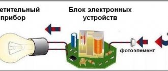
- Functional, it shows the node elements (depicted as rectangles), as well as the communication lines connecting them. A characteristic feature of this scheme is minimal detail. To describe the main functions of nodes, the rectangles displaying them are signed with standard letter designations. These can be various parts of the product that differ in functionality, for example, an automatic dimmer with a photo relay as a sensor or a regular TV. An example of such a scheme is presented below.
Example of a functional diagram of a television receiver - Fundamental. This type of graphic document displays in detail both the elements used in the design and their connections and contacts. The electrical parameters of some elements can be displayed directly in the document, or presented separately in the form of a table.
Example of a circuit diagram of a milling machine
If the diagram shows only the power part of the installation, then it is called single-line; if all elements are shown, then it is called complete.
Single Line Diagram Example
- Electrical wiring diagrams. These documents use positional designations of elements, that is, their location on the board, method and order of installation are indicated.
Installation diagram of a stationary flammable gas detector
If the drawing shows the wiring of the apartment, then the locations of lighting fixtures, sockets and other equipment are indicated on the plan. Sometimes you can hear such a document called a power supply diagram; this is incorrect, since the latter shows how consumers are connected to a substation or other power source.
Having dealt with the electrical circuits, we can move on to the designations of the elements indicated on them.
Set of tools for connecting a single-gang switch
To perform electrical work, you first need:
- turn off the power supply to the line;
- make sure there is no voltage;
- protect yourself from unauthorized switching on of electric current.
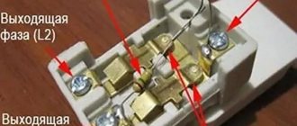
Using a special indicator, the phase wire coming into the junction box is determined. When found, you must mark it with a marker.
Then the tools are prepared:
- voltage indicator;
- pliers;
- screwdriver;
- marker;
- construction knife.
All these tools are freely available and inexpensive.