During the construction of fiber-optic transmission lines (FOTL), there is a need to connect the construction lengths of optical cables (OC). In this case, various methods of connecting optical fibers are used (welding, mechanical connectors). With any method of splicing fibers, the places where they are spliced must be reliably protected from adverse environmental influences. Therefore, splices of optical cable fibers are placed in special sealed containers - optical couplings.
An optical coupling selected for a fiber optic link for a specific purpose must provide the installation options necessary for it. For example:
- connecting coupling (straight) with two OKs inserted into the coupling;
- branching coupling with inputs into the coupling from three to twenty OK;
- branching coupling with “transit”, when the main cable and several branch cables are inserted into the coupling without cutting;
- connecting or branching coupling with the output of instrumentation wires from the OK armor.
The coupling must provide protection for the joint throughout the entire service life when exposed to temperatures characteristic of the place of its operation. The coupling must provide easy and convenient access inside for inserting additional OCs and laying connections of their fibers.
When selecting optical couplings, the following conditions should be taken into account:
- design features and sheath diameters of spliced optical cables;
- the number of OF connections that need to be made in the coupling;
- method of splicing optical fibers (welding with KDZS sleeves or connectors);
- number of cable entries into the coupling;
- features of the inputs (single inputs or OK input in transit, without cutting);
- location of installation of the coupling (well, pit, support);
- the need to secure and protect optical couplings at their installation sites;
- provision of instrument wire leads from the armor of spliced OK.
Domestic optical couplings
We bring to your attention tables for the selection of domestic optical couplings produced (OSD). A large assortment of SSD optical couplings allows you to choose options that are convenient for installation, which will allow you to implement specified design solutions at a minimum cost of couplings and additional accessories. For splicing optical cables, the SSD company produces optical couplings of the types MOG, MKO, MPO, MTOC and MOPG. Couplings are continuously improved and modernized in order to comply with changes occurring in the documents of the Ministry of Telecom and Mass Communications of the Russian Federation and leading telecom operators, as well as changes in the designs of optical communication cables. SSD optical couplings have a declaration of conformity with the current “Rules for the use of couplings for installation of communication cables” of 2006. The variety of designs of optical cables and placement of couplings corresponds to the same variety of designs of couplings and additional devices and devices for their installation, fastening and protection.
Features of the supply of SSD optical couplings
To ensure the possibility of creating stocks of couplings in the finished product warehouse and to complete them with everything necessary, after clarifying customer requests, all SSD optical couplings after manufacturing are delivered to the warehouse in the form of so-called basic kits. The basic kit of an optical coupling, as a rule, includes a coupling body with parts for its sealing, one cassette, KDZS sleeves and mounting materials. In the same way, kits for inserting OK of various designs into couplings and numerous additional accessories for couplings are delivered to the warehouse. After a conversation with the customer or after processing his request, a specialist from the SSD sales department generates an invoice, which includes the coupling and all additional products that the customer will need to install the coupling in the version he requires. To select optical couplings, consumers - designers, builders, representatives of fiber optic communication lines operation services - must formulate the conditions that the selected coupling must meet. Below is a series of tables from which, given the stated conditions, you can easily and quickly select a suitable coupling.
The tables show basic coupling sets with one cassette. If you need to connect a larger number of fibers in the coupling, you should additionally order sets of cassettes with mounting materials - ties, markers and KDZS sleeves.
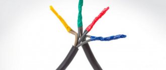
Types of cable connectors
To choose the right cable connector, you need to pay attention to the characteristics:
- type of insulation between phases;
- highest mains voltage;
- material of the cores and their cross-sectional area;
- number of cores in the cable.
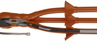
Installation of SIP cable from pole to house
We produce products used in low-voltage networks (up to 1000 V) and intended for high-voltage switching. Epoxy products are most resistant to environmental influences.
Important! To install the product correctly, you need to correctly cut the ends and remove the insulating layer. At the ends of the wires, it should also be removed over a length half as long as the length of the coupling. The ends are then inserted into the latter and connected with fasteners. Typically, one copy can connect no more than 4 wires.
Couplings
The coupling for mounting on the cable is marked with the following markings (interpretation is given from left to right):
- the first digit shows the operating voltage - for example, if it is 1 (the most common option), the product is intended for networks up to 1000 V;
- the letter C indicates that the component is intended for connection;
- “tp” denotes thermoplastic properties;
- then the number of wires to be connected is indicated, for example, 4;
- two three-digit numbers indicate the range of possible cross-sectional areas (mm);
- the letter C indicates the presence of the supplied fasteners;
- the letter P means that the wiring is made of PVC.
Sometimes after the indication of thermoplasticity there is a letter O (indicates that the part is designed for a single-core cable), P (repair element) or B (presence of armor).
Transition couplings
These couplings are used when it is necessary to connect cables of different types. They are reliable and durable.
Connections with transition elements
End couplings
They are used for wires with an insulating layer of paper. Their markings are generally similar to the connecting parts, but there are some differences:
- the second character instead of the letter C is K (indicates the end piece), followed by B or H (type of installation - internal or external);
- at the end there is a letter H - it indicates the presence of fasteners.
Installing a locking device on couplings
Parts equipped with such a device are mounted to protect the insulation from melting caused by high temperature. The stopper is made of metal rods connected to each other, covered with paper. They are mounted into a panel with a brass frame and then into a capsule.
Couplings with insulation made of heat-shrinkable tubing
Installation of a heat-shrinkable sleeve on a power cable is simple, thanks to the presence of lightweight polymer parts in the design. For crimping, use a hair dryer, setting it at 150 degrees. The design is durable and can last up to 20 years.
Heat-shrinkable sleeve
Cold shrink insulated couplings
Here, complex elastomeric technology is used, when a dielectric layer is applied to a power line that needs insulation through certain manipulations. It is suitable for areas with a high fire hazard.
Couplings for optical cable with one sheath and without armor for sewerage
Installation and placement conditions:
- cables are laid in cable ducts;
- direct and branching couplings with the number of inputs from 3 to 8 are required;
- optical fibers are connected by welding with the joints protected by KDZS sleeves;
- couplings must provide the possibility of transit input;
- number of fiber connections - up to 144;
- couplings are placed in cable sewer wells, city sewers, in cable entry rooms at automatic telephone exchanges, in technical rooms;
- costs for couplings and parts for their installation should be minimal.
| Cable brands | Outer diameter OK, mm | Number of welded joints in the coupling | Number of OK inputs into the coupling according to the project | Coupling size |
| DPO; DAO | 9 – 14 | Up to 144 | 2 – 4 | MOG-T3-40 (OK up to 22 mm) MOG-T5-40 (OK up to 19 mm) |
| 6 – 8 | MOG-U-33-1K4845 MOG-U-44-1K4845 MOG-S-33-1K4845 MOG-S-44-1K4845 MOG-U-34 Clamp MOG-U-44 Clamp MTOC-L7/48 transit MTOC-L6/108 transit MTOC-L6/144 transit | |||
| Transit + 3 | MOG-U-23-1K4845 MOG-S-23-1K4845 | |||
| Transit + 4 | MOG-U-24-1K4845 MOG-S-24-1K4845 MOG-U-24 Clamp MTOC-L7/48 transit MTOC-L6/108 transit MTOC-L6/144 transit |
Common mistakes in installing end couplings
All about cable installation
When installing coupling connections, craftsmen make typical mistakes.
Failure to maintain the required distance
It is especially important to monitor the interphase distance when working on high voltage lines. Ignoring this requirement threatens insulation breakdown. If the shield is too small, you will need to buy adapters.
Cross phase orientation
Do not allow different types of wiring to come into contact. This is fraught with field tension.
Tips with window for checking connection status
They can only be used indoors, securely protected from precipitation. If water gets into the window, the metal parts will begin to oxidize.
Installation of protective elements on the cores of outdoor couplings
These elements are required to prevent moisture from getting inside. The protective parts must also not be allowed to touch each other.
Air masses in the housing
This leads to the formation of ions in the gas space, which damages the protective part. During installation, it is necessary to seal the cracks with sealant.
Optical couplings for cables with one sheath and without armor for PTA
Installation and placement conditions:
- cables are laid in protective polyethylene pipes (PPP);
- direct and branch couplings with the number of inputs from 3 to 12 are required;
- optical fibers are connected by welding with the joints protected by KDZS sleeves;
- couplings must provide the possibility of transit input;
- number of fiber connections - from 48 to 288;
- couplings are placed in underground steel or plastic containers, in technical rooms;
- the design and dimensions of the couplings must ensure their placement with OK reserves in underground containers of the types POD, KOT-2, etc.
| Cable brands | Outer diameter OK, mm | Number of welded joints in the coupling | Number of OK inputs into the coupling according to the project | Coupling size |
| DPO; DAO | 9 – 20 | Up to 108 | 2 – 6 | MTOC-L7/48 transit MTOC-L6/108-1KT3645-K MTOC-L6/144 transit |
| Transit + 4 | ||||
| Up to 216 Up to 288 | 2 – 10 | MTOC-G3/216-1KT3645-K MTOC-G3/240 transit (1 cassette) MTOC-G3/288-8KT3645-K | ||
| 2 – 12 | MTOC-D3/216 transit (1 cassette) MTOC-D3/240 transit (1 cassette) | |||
| Transit + 6 | MTOC-G3/216-1KT3645-K MTok-G3/240 transit (1 cassette) | |||
| Transit + 8 | MTOC-D3/216 transit (1 cassette) MTOC-D3/240 transit (1 cassette) |
Power cable couplings: types, brands, design, application (connecting, end)
For terminating cables, as well as for connecting construction lengths of cables, end and connecting couplings are used, respectively.
Branch couplings can be considered a type of coupling, which are used to connect and branch power cables with voltages up to 1 kV. The designs of couplings are very diverse and are determined by the type of power cables and their insulation, the operating voltage, the conditions of installation and placement of couplings, etc.
Impregnated rolls of cable paper are used to insulate paper-insulated cable joints. This insulation is applied manually at the installation site, which complicates the installation process. In addition, the reduced electrical strength of the paper winding leads to an increase in the dimensions of the couplings.
Rice.
10. Design elements of a SS brand lead coupling for 6-10 kV cables with paper insulation. To connect three-core cables with impregnated paper insulation in a common sheath for voltages of 6 and 10 kV, SS brand lead couplings have become widespread (see Fig. 10 ).
Connectors for cables for voltage 1 kV have a cast iron body. Connectors for cables for voltages of 20 and 35 kV have a brass casing, which, when laid in the ground, is placed in a common cast-iron, steel or fiberglass casing. The metal body of the couplings is filled with oil rosin compound or potting mixture.
The design and installation of cable joints is greatly simplified when prefabricated parts are used for their installation. For these purposes, for example, epoxy compounds are used. Insulation made from epoxy compounds has sufficient mechanical strength and good adhesion to metal and various materials. In addition, epoxy compounds have the ability to harden at ambient temperature or with slight heating.
For paper-insulated cables, in particular, epoxy couplings of the SEF brand are used (see Fig. 11), epoxy termination couplings for internal installation of the KVEL brand (see Fig. 12) and for external installation of the KNE brand (see Fig. 13).
Rice. 11. Type and design elements of the SEF brand epoxy coupling for 6-10 kV cables with paper insulation
Rice. 12. Type and design elements of an epoxy termination for internal installation of the KVEL brand for 6-10 kV cables with paper insulation
Rice. 13. Type and design elements of an epoxy termination coupling for outdoor installation of the KNE brand for 1, 6 and 10 kV cables with paper insulation.
The disadvantage of cast epoxy insulation is its relatively low electrical strength compared to impregnated paper insulation. However, the use of advanced casting methods that ensure a fairly uniform composition of the casting makes it possible to use epoxy compounds as insulation for cable joints with voltages up to 35 kV inclusive.
Currently, in the Russian electric power industry, heat-shrinkable cable couplings are becoming increasingly widespread for power cables of low and medium voltage classes, which have significant advantages over couplings based on casting compounds and insulating winding materials. The use of technology for installing end and connecting couplings based on the structural elements of heat-shrinkable cross-linked polymers (polyethylene, polyvinyl chloride), which have the ability to undergo significant shrinkage when heated, allows for complete sealing of cables and good insulating properties of the couplings, as well as significantly reducing the installation time of the couplings. A wide range of heat shrinkability of structural parts and elements of couplings makes it possible to significantly unify standard sizes of couplings and use one standard size for several types of cables and sections of their cores.
Rice. 14. Heat-shrinkable end sleeves for indoor and outdoor installation from Raychem for cables 6, 10, 20 and 35 kV. for cables 6–35 kV for connecting cables 6–35 kV with paper insulation with paper and plastic insulation
In the early 90s, heat-shrinkable cable sleeves from Raychem, which is one of the leading companies in the production of heat-shrinkable cable fittings, were offered to the Russian market. These couplings can be used for both paper-insulated cables and plastic-insulated cables (see Figures 14 and 15).
Rice. 15. Heat-shrinkable couplings from Raychem
Rice. 16. Heat-shrinkable coupling from “Thermo-fit” company for single-core cables 10 kV brand 10STpOM.
Rice. 17. Heat-shrinkable transition coupling from Termofit for connecting three-core cables with paper insulation and three single-core cables with plastic insulation for a voltage of 10 kV, brand 10STpP.
Among the domestic manufacturers and suppliers of heat-shrinkable cable fittings, one can highlight JSC Mikhnevsky Electrical Products Plant, JSC Podolsk Electrical Products Plant and a number of other companies (see Fig. 16–18).
Rice. 18. Heat-shrinkable couplings from the company “Podolsk Electrical Installation Products Plant”
It should be noted that heat-shrinkable cable couplings from domestic companies, while not inferior in basic characteristics and ease of installation to the couplings from Raychem, have a significant advantage in price, which is significantly lower than that of foreign analogues.
The widespread introduction of new technology heat-shrinkable cable fittings in the construction, reconstruction and repair of cable lines will help improve the reliability of operation and manufacturability of the installation of cable lines, reduce installation time, and increase environmental safety for personnel and the environment.
Optical sleeves for cables with two sheaths and armor made of corrugated steel tape
Installation and placement conditions:
- cables are laid in cable ducts;
- direct and branching couplings with the number of inputs from 3 to 8 are required;
- optical fibers are connected by welding with the joints protected by KDZS sleeves;
- couplings must provide the possibility of transit input;
- number of fiber connections - up to 144;
- couplings are placed in cable sewer wells, city sewers, in cable entry rooms at automatic telephone exchanges, in technical rooms;
- costs for couplings and parts for their installation should be minimal.
| Cable brands | Outer diameter OK, mm | Number of welded joints in the coupling | Number of OK inputs into the coupling according to the project | Coupling size |
| DPL; DAL | 12 – 19 | Up to 144 | 2 – 4 | MOG-T3-40 (OK up to 22 mm) MOG-T5-40 (OK up to 19 mm) |
| 6 – 8 | MTOC-L7/48 transit MTOC-L6/108 transit MTOC-L6/144 transit MOG-U-33-1K4845 MOG-U-44-1K4845 MOG-S-33-1K4845 MOG-S-44-1K4845 MOG-U-34 Clamp MOG-U-44 Clamp | |||
| Transit + 3 | MOG-U-23-1K4845 MOG-S-23-1K4845 | |||
| Transit + 4 | MOG-U-24-1K4845 MOG-S-24-1K4845 MOG-U-24 Clamp MTOC-L7/48 transit MTOC-L6/108 transit MTOC-L6/144 transit |
Technical requirements for couplings
If you carefully examine the cable connected by means of a coupling, you will notice that this part sequentially connects individual fragments of the cable fabric to each other. Because of this, the coupling for the power cable must also transmit electricity with minimal losses.
It is very important that the area of contact between the connecting element and the cable conductors corresponds to the size of the conductors, and ideally even be a little larger. We should not forget about the crimping force. It must not only guarantee reliable contact from a mechanical point of view, but also the normal movement of electric current with minimal resistance.
For the above reasons, the cores of any cable are secured using:
- tips, which are subsequently fixed with fasteners;
- special sleeves with additional fasteners and crimping.
End coupling
The insulating layer of the connecting element must:
- easy to transfer phase-to-phase voltage;
- have sufficient resistance to mechanical stress to protect the housing from breakdowns;
- resist the harmful effects of soil and groundwater for quite a long time.
Return to content
Optical cable joints with one sheath and armor made of corrugated steel tape
Installation and placement conditions:
- cables are laid in cable ducts;
- direct and branching couplings with the number of inputs from 3 to 8 are required;
- optical fibers are connected by welding with the joints protected by KDZS sleeves;
- couplings must provide the possibility of transit input;
- number of fiber connections - up to 144;
- couplings are placed in cable sewer wells, city sewers, in cable entry rooms at automatic telephone exchanges, in technical rooms;
- costs for couplings and parts for their installation should be minimal.
| Cable brands | Outer diameter OK, mm | Number of welded joints in the coupling | Number of OK inputs into the coupling according to the project | Coupling size |
| DOL; TPL | 9 – 14 | Up to 144 | 2 – 4 | MOG-T3-40 (OK up to 22 mm) MOG-T5-40 (OK up to 19 mm) |
| 6 – 8 | MTOC-L7/48 transit MTOC-L6/108 transit MTOC-L6/144 transit MOG-U-33-1K4845 MOG-U-44-1K4845 MOG-S-33-1K4845 MOG-S-44-1K4845 MOG-U-34 Clamp MOG-U-44 Clamp | |||
| Transit + 3 | MOG-U-23-1K4845 MOG-S-23-1K4845 | |||
| Transit + 4 | MOG-U-24-1K4845 MOG-S-24-1K4845 MOG-U-24 Clamp MTOC-L7/48 transit MTOC-L6/108 transit MTOC-L6/144 transit |
Optical couplings for cables with two sheaths and armor made of galvanized steel wires
Installation and placement conditions:
- cables are laid in soils of all categories;
- direct and branching couplings with the number of inputs from 3 to 6 are required;
- optical fibers are connected by welding with the joints protected by KDZS sleeves;
- couplings must provide the possibility of transit input;
- number of fiber connections - up to 288;
- couplings are placed in cable sewer wells, city sewers, in cable entry rooms at automatic telephone exchanges, in technical rooms;
- the couplings must ensure that the instrument wires are brought out from the armor of each cable.
| Cable brands | Outer diameter OK, mm | Number of welded joints in the coupling | Number of OK inputs into the coupling according to the project | Coupling size |
| DPS; TPS | 13 – 19 | Up to 144 | 3 + 3 for instrument wires | MTOC-M6/144-1KT3645-K-44 |
| Up to 240 | 3 + 3 for instrument wires | MTOC-A1/216-1KT3645-K-77 MTOC-A1/240 (2 inputs No. 7) | ||
| Up to 240 | 4 + 4 for instrument wires | MTOK-B1/216-1KT3645-K-44 MTOK-V2/216-1KT3645-K-44 MTOC-B1/240 transit (2 inputs No. 4) MTok-V2/240 (2 inputs No. 4) | ||
| Up to 240 | Transit + 4 for OK | MTOK-B1/216-1KT3645-K-44 MTOK-V2/216-1KT3645-K-44 MTOC-B1/240 transit (2 inputs No. 4) MTok-V2/240 (2 inputs No. 4) |
End
Cable couplings offered by EnergoKomplekt LLC are designed to protect the ends and insulate the cores of conductor products and have high heat resistance.
They can be cold and thermal shrinkage, internal (KVTp) and external (KNTp) installation (as well as combined KVNTp). The choice of the product to be installed primarily depends on the design features of the cable, its insulating coating and cross-section, and the voltage used. For example, PKT grades are used for cables with plastic insulation. End,
are sold by the company, for conductors with a cross section of 25-50, 70-120, 150-240 mm2, for voltages of 1, 6, 10.20, 35 kV. The complete set includes the use of bolted and pressed ends, as well as complete sealing using thermally fusible adhesive.
| Brand | Cable insulation | Cable brands | Availability of reservation |
| 3KVNTp-1 | paper | AABl, (A)SBl, (A)SBG, AAG, (A)SG, AABv, (A)SBShv, AAShv, (A)SShv, AAB2lShv, (A)SB2lShv, (A)SKl | with tape and wire armor, as well as without armor |
| 4KVNTp-1 |
Explanation of the designation 3KVNTp-1 25/50: 3 – for a cable with three cores K – end VN – internal and external installation T – heat-shrinkable p – glove included 1 – cable voltage 1 kV 25/50 – cable cross-section (mm2)
| Brand | Cable insulation | Cable brands | Availability of reservation |
| 1PKT-1 | plastic | (A)VVG (A)VVGz (A)PvVG NYM NYY | without reservation |
| 4PKTp-1 | |||
| 5PKTp-1 | |||
| 4PKTp(b)-1 | (A)VBBShv (A)PvBbShv (A)PvBbShp (A)VBV (A)VVB (A)VVBG (A)PvKShv (A)PvKShp | with tape and wire armor | |
| 5PKTp(b)-1 |
Explanation of the designation 4PKTp(b)-1: 4 - four cores P - plastic insulation K - end T - heat-shrinkable p - there is a glove b - with armor 1 - voltage 1 kV
Optical couplings for overhead cables with a remote power element
Installation and placement conditions:
- the cables are suspended on the supports of overhead lines and power lines, on racks;
- direct and branch couplings with a number of inputs from 3 to 12 are required;
- optical fibers are connected by welding with the joints protected by KDZS sleeves;
- couplings must provide the possibility of transit input;
- number of fiber connections – from 48 to 240;
- couplings are placed on supports, in cabinets, and in technical rooms.
| Cable brands | Outer diameter OK, mm | Number of welded joints in the coupling | Number of OK inputs into the coupling according to the project | Coupling size |
| DPOm; DPOd; TPOm; TPOd | 9 – 20 | Up to 48 | 6 | MTOC-L7/48-1KS1645-K |
| Up to 108 | 6 | MTOC-L6/108-1KT3645-K | ||
| Up to 144 | 6 | MTOC-L6/144 transit | ||
| Up to 216 | 10 – 12 | MTOC-G3/216-1KT3645-K MTOC-D3/216 transit (1 cassette) | ||
| Up to 240 | 10 – 12 | MTok-G3/240 transit (1 cassette) MTOC-D3/240 transit (1 cassette) | ||
| Up to 108 | Transit + 4 | MTOC-L6/108-1KT3645-K | ||
| Up to 144 | Transit + 4 | MTOC-L6/144 transit | ||
| Up to 216 | Transit + 6-8 | MTOC-G3/216-1KT3645-K MTOC-D3/216 transit (1 cassette) | ||
| Up to 240 | Transit + 6-8 | MTok-G3/240 transit (1 cassette) MTOC-D3/240 transit (1 cassette) |
Classification of heat-shrinkable couplings
| Brand | Cable insulation | Cable brands | Availability of reservation | Purpose of the coupling | Number of cable cores | Cable voltage |
| 3KVNTp-1 | paper insulation | AABl, (A)SBl, (A)SBG, AAG, (A)SG, AABv, (A)SBShv, AAShv, (A)SShv, AAB2lShv, (A)SB2lShv, (A)SKl | with tape and wire armor, as well as without armor | terminal | 3 | 1 kV |
| 4KVNTp-1 | 4 | |||||
| 3STp-1 | connecting | 3 | ||||
| 4STp-1 | 4 | |||||
| 1PKT-1 | plastic insulation | (A)VVG (A)VVGz (A)PvVG NYM NYY | without reservation | terminal | 1 | |
| 4PKTp-1 | 4 | |||||
| 5PKTp-1 | 5 | |||||
| 1PST-1 | connecting | 1 | ||||
| 4PST-1 | 4 | |||||
| 5PST-1 | 5 | |||||
| 4PTO-1 | branch | 4 | ||||
| 5PTO-1 | 5 | |||||
| 4PKTp(b)-1 | (A)VBBShv (A)PvBbShv (A)PvBbShp (A)VBV (A)VVB (A)VVBG (A)PvKShv (A)PvKShp | with tape and wire armor | terminal | 4 | ||
| 5PKTp(b)-1 | 5 | |||||
| 4PST(b)-1 | connecting | 4 | ||||
| 5PST(b)-1 | 5 | |||||
| 4PTO(b)-1 | branch | 4 | ||||
| 5PTO(b)-1 | 5 |
| Brand | Insulation | Brand | Availability of reservation | Purpose of the coupling | Number of cores | Voltage |
| 3PKTp-6 | plastic insulation | (A)VVG (A)VBbShv (A)PvBbShv | with and without armor | terminal | 3 | 6 kV |
| 3PST-6 | connecting | 3 |
| Brand | Insulation | Brand | Availability of reservation | Purpose of the coupling | Number of cores | Voltage |
| 3KVTp-10 | paper insulation | AABl, (A)SBl, (A)SBG, (A)SG, AABv, (A)SBShv, AAShv, (A)SShv, AAB2lShv, (A)SB2lShv, Ts(A)SB, Ts(A)SB2l | with belt armor and without armor | terminal | 3 | 10 kV |
| 3KNTp-10 | ||||||
| 3STp-10 | connecting | |||||
| 1PKVT-10 | XLPE insulation | (A)PvV (A)PvPu (A)PvPug (A)PvPg (A)PvP2g (A)PvPu2g (A)PvBP (A)PvBV (A)PvKV (A)PvKPg | with tape and wire armor, as well as without armor | terminal | 1 | 10 kV |
| 1PKNT-10 | 1 | |||||
| 3PKVTp-10 | 3 | |||||
| 3PKNTp-10 | 3 | |||||
| 1PST-10 | connecting | 1 | ||||
| 3PST-10 | 3 | |||||
| PSPTp-10 | transitional | 3+3*1 |
| Brand | Insulation | Brand | Availability of reservation | Purpose of the coupling | Number of cores | Voltage |
| 1PKVT-20 | XLPE insulation | (A) PvPu, (A) PvPug, (A) PvV, (A) PvP, (A) PvP2g, (A) PvPu2g, (A) PvKV, (A) PvKPg | with wire armor and without armor | terminal | 1 | 20 kV |
| 1PKNT-20 | ||||||
| 1PST-20 | connecting |
| Brand | Insulation | Brand | Availability of reservation | Purpose of the coupling | Number of cores | Voltage |
| 1PKVT-35 | XLPE insulation | (A) PvPu, (A) PvPug, (A) PvV, (A) PvP, (A) PvP2g, (A) PvPu2g, (A) PvKV, (A) PvKPg | with wire armor and without armor | terminal | 1 | 35 kV |
| 1PKNT-35 | ||||||
| 1PST-35 | connecting |
Optical couplings for suspended self-supporting cables with two sheaths
Installation and placement conditions:
- the cables are suspended on the supports of overhead lines and power lines, on racks;
- direct and branch couplings with a number of inputs from 3 to 6 are required;
- optical fibers are connected by welding with the joints protected by KDZS sleeves;
- couplings must provide the possibility of transit input;
- number of fiber connections - up to 216;
- couplings are placed on supports and installed in technical rooms.
| Cable brands | Outer diameter OK, mm | Number of welded joints in the coupling | Number of OK inputs into the coupling according to the project | Coupling size |
| DPTa; DPTs | 12 – 22 12 – 20 | Up to 108 | 5 | MTOC-K6/108-1KT3645-K |
| Up to 216 | 8 | MTOC-V3/240 transit | ||
| Up to 240 | 8 | MTOC-V3/216-1KT3645-K | ||
| Up to 108 | Transit + 3 | MTOC-K6/108-1KT3645-K | ||
| Up to 216 | Transit + 4 | MTOC-V3/216-1KT3645-K | ||
| Up to 240 | Transit + 4 | MTOC-V3/240 transit |
Heat-shrinkable 4PST-1, 5PST-1
designed for connecting 4 and 5-core carriers with plastic insulation with and without armor for voltages up to 1 kV. Types: (A)VVG, NYM, (A)PvVG, (A)VBbShv, (A)VBV, AVVB, (A)VVBG, (A)PvBbShv, (A)PvBbShp. Insulating cuffs with an internal sublayer of hot-melt adhesive provide reliable and high-quality insulation of the connection points of the cores. Hot-melt adhesive applied to the inner surface of the connecting cuffs and casing ensures complete sealing of the coupling after installation. For armored cables, a non-soldered grounding system is used. The Belt Armor Coupling Kit includes a flat ground wire and 2 constant pressure springs for mounting the ground wire to the armor strips. The casing reliably protects, seals and reinforces the connection. The kit is universal and allows you to use both crimp sleeves and bolted connectors.
| equipment and name | number of cores | core cross-section (mm²) | |
| without bolt connectors | with bolt connectors | ||
| for cables without armor: | |||
| 4PST-1-16/25 | 4PST-1-16/25(B) | 4 | 16 — 25 |
| 4PST-1-25/50 | 4PST-1-25/50(B) | 4 | 25 — 50 |
| 4PST-1-70/120 | 4PST-1-70/120(B) | 4 | 70 — 120 |
| 4PST-1-150/240 | 4PST-1-150/240(B) | 4 | 150 — 240 |
| 5PST-1-16/25 | 5PST-1-16/25(B) | 5 | 16 — 25 |
| 5PST-1-25/50 | 5PST-1-25/50(B) | 5 | 25 — 50 |
| 5PST-1-70/120 | 5PST-1-70/120(B) | 5 | 70 — 120 |
| 5PST-1-150/240 | 5PST-1-150/240(B) | 5 | 150 — 240 |
| for cables with armor: | |||
| 4PST(b)-1-16/25 | 4PST(b)-1-16/25(B) | 4 | 16 — 25 |
| 4PST(b)-1-25/50 | 4PST(b)-1-25/50(B) | 4 | 25 — 50 |
| 4PST(b)-1-70/120 | 4PST(b)-1-70/120(B) | 4 | 70 — 120 |
| 4PST(b)-1-150/240 | 4PST(b)-1-150/240(B) | 4 | 150 — 240 |
| 5PST(b)-1-16/25 | 5PST(b)-1-16/25(B) | 5 | 16 — 25 |
| 5PST(b)-1-25/50 | 5PST(b)-1-25/50(B) | 5 | 25 — 50 |
| 5PST(b)-1-70/120 | 5PST(b)-1-70/120(B) | 5 | 70 — 120 |
| 5PST(b)-1-150/240 | 5PST(b)-1-150/240(B) | 5 | 150 — 240 |
Optical couplings for single-sheath self-supporting overhead cables
Installation and placement conditions:
- the cables are suspended on the supports of overhead lines and power lines, on racks;
- direct and branch couplings with a number of inputs from 3 to 12 are required;
- optical fibers are connected by welding with the joints protected by KDZS sleeves;
- couplings must provide the possibility of transit input;
- number of fiber connections – up to 240;
- couplings are placed on supports and installed in technical rooms.
| Cable brands | Outer diameter OK, mm | Number of welded joints in the coupling | Number of OK inputs into the coupling according to the project | Coupling size |
| DPT(L) | 10 – 20 | Up to 108 | 5 | MTOC-K6/108-1KT3645-K |
| Up to 216 | 8 | MTOC-V3/216-1KT3645-K | ||
| Up to 240 | 8 | MTOC-V3/216-1KT3645-K | ||
| Up to 108 | Transit + 3 | MTOC-K6/108-1KT3645-K | ||
| Up to 216 | Transit + 4 | MTOC-V3/216-1KT3645-K | ||
| Up to 240 | Transit + 4 | MTOC-V3/240 transit |
Heat-shrinkable 4STp-1, 3STp-1
designed for connecting 4- and 3-wire lines with oil-impregnated paper insulation, with or without armor, with a common aluminum or lead sheath, for voltages up to 1 kV. Types of installed wiring: AABl, (A)SBl, (A)SBG, AAG, (A)SG, AABv, (A)SBShv, AAShv, (A)SShv, AAB2lShv, (A)SB2lShv. Insulating cuffs provide reliable and high-quality insulation of the connection points of the cores. The use of oil-resistant material tubes prevents oil from leaking out and drying out the paper insulation. Hot-melt adhesive applied to the inner surface of the connecting cuffs, gloves and casing ensures complete tightness after installation. Installation of the jumper wire connecting the sheaths and armor tapes at both ends of the cable is carried out in a combined way. The basic package includes constant pressure springs used to secure the ground wire to the metal sheaths. Fastening to armored belts is carried out by soldering. The presence of constant pressure springs for fastening the grounding wire to the metal sheaths of the connected cables ensures quick and reliable installation. The use of a spring eliminates the possible risk of thermal damage to the paper insulation under the aluminum shell in case of soldering using refractory solder. The kit is universal and allows you to use both crimp sleeves and bolted connectors.
| equipment and name | number of cores | core cross-section (mm²) | |
| without bolt connectors | with bolt connectors | ||
| 4STp-1-25/50 | 4STp-1-25/50(B) | 4 | 25 — 50 |
| 4STp-1-70/120 | 4STp-1-70/120(B) | 4 | 70 — 120 |
| 4STp-1-150/240 | 4STp-1-150/240(B) | 4 | 150 — 240 |
| 3STp-1-25/50 | 3STp-1-25/50(B) | 3 | 25 — 50 |
| 3STp-1-70/120 | 3STp-1-70/120(B) | 3 | 70 — 120 |
| 3STp-1-150/240 | 3STp-1-150/240(B) | 3 | 150 — 240 |
Couplings and cable entries for cables built into a lightning protection cable (OPGT)
Installation and placement conditions:
- OPGW cables are suspended on power transmission line supports;
- they are spliced in straight and branch couplings with the number of inputs from 3 to 4;
- transit inputs are not provided;
- there are couplings and inputs for sections of lines with melting of ice on OPGW;
- optical fibers are connected by welding with the joints protected by KDZS sleeves;
- number of fiber connections – up to 216;
- couplings are placed on power transmission line supports on BS type drums or on brackets for MRPGs;
- OPGW cables are used as the main cables;
- self-supporting dielectric cables are used as branch cables;
- for input into the couplings of OPGT cables, KVG type bushings are used;
- to enter self-supporting OK couplings, KVSm and KVSts bushings are used;
- for cable entry in areas with ice melting, kits with the letter “P” are used: KVGP, KVSmP and KVStsP;
- selection of cable glands for OPGW is carried out taking into account the outer diameter of the OPGW and the number and size of modules; they are indicated in the OPGT labeling;
- selection of cable glands for self-supporting cable terminals is made taking into account their design;
- cables with a modular core are inserted into a coupling with the KVSm and KVSmP kits;
- cables with a central tube are inserted into a coupling with the KVSts and KVStsP kits;
- The diameters of self-supporting cables can be from 6 to 22 mm.
| Cable brands | Outer diameter OK, mm | Number of welded joints in the coupling | Number of OK inputs into the coupling according to the project | Coupling size |
| OCGT | 8 – 20 | Up to 64 | 3 | MOPG-M-2/64-4KS1645-K |
| Up to 128 | 4 | MOPG-M-1/128-4KU3260 | ||
| Up to 128 | 4 in the area with ice melting | MOPG-MP-1/128-4KU3260 | ||
| Up to 216 | 4 | MOPG-M-1/216-6KT3645-K | ||
| Up to 216 | 4 in the area with ice melting | MOPG-MP-1/216-6KT3645-K |
Cable sleeves
are intended for connecting electrical cables into a single line and for their supply to electrical installations, overhead power lines, station-type structures, as well as for creating connections with control taps. The coupling
consists of elements, the presence of which allows us to ensure the reliability of electrical contact and the mechanical integrity of the connection, taking into account the design features of the wire.
The classification of heat-shrinkable couplings is described in a tabular manner. (watch here.)
Cable couplings offered in the assortment, from EnergoKomplekt LLC:
- End terminals KVNTp, PKTp
- Branch PHEs
- Connecting STP, PST
Couplings
consist of such elements as: - Glove (for moving the cores away from each other to prevent interphase short circuits);
— Grounding kit; — Heat-shrinkable tubes; — Marking cuffs; — Disc insulators (in some models); — Cable lugs. Explanation of symbols:
- 1,3,4 - number of cores
- K - end
- C - connecting
- B – internal installation
- N - outdoor installation
- T - Heat-shrinkable technology
- n - presence of gloves
- P - for cable with plastic insulation
- b - for cable with armor
- M - with bolted connectors and lugs
- 1,6,10 - rated voltage
- (25-50), (70-120), (150-240) - cable cross-section
- k - for control taps
- E-epoxy fill
Note
If it is necessary to splice optical fibers using mechanical connectors, MTOC type couplings can be supplied with cassettes that have holders for installing certain types of connectors.
For example:
- Upon pre-order, MTok-K6 and MTok-L6 couplings can be supplied with KM cassettes equipped with two cradle for connectors: - RECORDsplice type (maximum cassette capacity - 20 connectors), - Fibrlok type (maximum cassette capacity - 10 connectors).
- Up to three such cassettes can be installed in each coupling.