Electrics in an aerated concrete house are perhaps the only type of communications that can be installed after the box has been erected - and even after finishing work has been completed. Installation must be carried out in accordance with the requirements of the PUE, which will definitely be taken into account in today's material.
Electrical wiring in a house made of aerated concrete is not much different from similar work in other buildings, but there are still some peculiarities. Let's talk about this in more detail.
Calculation of power consumption and cable selection
To determine the characteristics of the required electrical cable, it is necessary to calculate the power consumption of all possible electrical appliances in the house. Let us immediately note that it is necessary to use copper wires.
For a socket group, the cable cross-section should be from 2.5 mm. Sq., for lighting – from 1.5 mm. sq. To connect powerful electrical appliances, such as a boiler, electric stove, fireplaces, etc., the cable cross-section should be from 4 mm. Sq.
Preparatory work
Before starting the actual installation of electrical wiring, it is necessary to perform some preliminary actions, the purpose of which will be to eliminate mistakes and hasty and often dangerous decisions. It is necessary to immediately take into account that fire safety depends on the quality of installation work. In this case, it is impossible to play it safe; electrical wiring in a house made of aerated concrete is no less dangerous than in a building made of any other material.
First of all, you need to draw up a plan of all the premises. It is not necessary to carry it out in strict accordance with the requirements of GOST; you can make a working sketch. The main task of this plan is the placement of electrical wiring, routing, and determination of convenient installation points for switches and sockets. In addition, you need to choose the optimal placement of lighting fixtures (modern design solutions differ significantly from the chandeliers in the center of the room that were common since Soviet times).
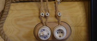
It is better to position the switches so that in the dark you do not have to frantically fumble along the wall with your hand. It is most convenient to place them at the level of the palm of the freely lowered hand. The number of sockets should be such as to avoid the need to use extension cords. This especially applies to the kitchen, living room and study, where a lot of kitchen, computer and other equipment, lighting fixtures, televisions, stereo systems, etc. are used. Practice shows that there are no extra sockets in the house - no matter how many there are, you have to use tees or extension cords somewhere.
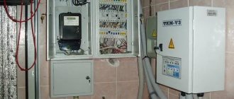
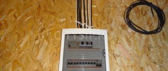
In addition, you must immediately decide on the location of the main panel, machines and other devices. It is necessary to immediately resolve the issue of the possibility of a three-phase power supply (this should be discussed with local power grids or other supervisory organizations). In a private house, the presence of three-phase power is a big bonus - you can start electric motors, use fairly powerful ventilation, and install some machines and devices in the garage.
Single-wire or multi-wire conductor
The single-wire cable core is more rigid and breaks if it is bent frequently. It is used specifically for stationary electrical wiring, since it is cheaper than multi-wire and easier to install.
The stranded core is very flexible, used for hard-to-reach places and for connecting portable equipment.
Use of transformers and stabilizers
Unstable voltage in the network is a common problem in homes, and this can cause not only breakdown of electrical appliances, but even damage to electrical wiring.
Such problems can be solved by using a voltage transformer, which is a statistical electrical device that converts voltage. You can order such a device on the website newet.ru. The principle of a transformer is that it levels out and smoothes out power surges, protecting the entire electrical system of the home.
Wiring diagrams
The reliability of electrical wiring, ease of use, and the consumption of wires and components depend on the connection diagram.
The following types (schemes) of connection are distinguished:
- All sockets and light bulbs are connected through one machine.
- All sockets are connected through one circuit breaker, all light bulbs through another.
- In each separate room there is a machine with sockets, and all the lighting is connected to another machine.
House wiring and wiring plan
The electrical wiring plan is a very important and responsible step, which you need to understand very well yourself, or resort to the services of specialists.
At the planning stage, you need to schematically indicate the following elements:
- Shield.
- Wires.
- Sockets.
- Lamps (light bulbs).
- Switches.
- Automatic machines.
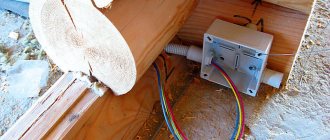
- Distribution boxes.
Marking the room
In order to mark the room you will need:
- ordinary building level;
- water or laser level;
- construction pencil;
- beating thread;
- roulette.
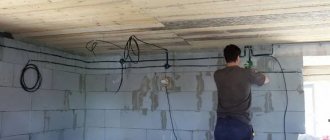
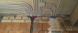
Initially, using a laser level (water level) and a tape measure, we mark the installation locations of sockets and switches. Next, using a building level or a laser level and a pencil (mark), we mark the descents from the ceiling to the sockets and switches using strictly horizontal lines for subsequent cutting.
Using a laser level, we mark on the ceiling the places where cable and conductor products will be laid for the subsequent installation of fasteners for corrugations and cable laying.
We mark the installation location of the distribution box, which should be selected in such a way that the costs of cable and wire products are minimal.
Tags: automatic, boiler, sconce, car, view, choice, switch, house, , cable, how, design, circuit, , installation, lighting, heating, connection, wire, project, laying, cable laying, start-up, repair , socket, light, lamp, term, ten, type, current, , shield, electrical panel
Hidden and exposed wiring
Hidden wiring is an option when wires are hidden in the walls, ceiling and floor. Grooves are made in the walls, cables are laid in them and covered with plaster. Corrugated wiring in floors is filled with concrete screed. On ceilings, corrugated cables are covered with suspended ceilings, plastic panels and other hanging materials.
The main purpose of hidden wiring is visual perception and additional decorative options.
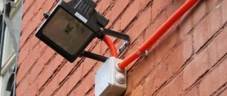
Open wiring is an option when corrugated cables are laid outside the walls in special cable channels. Cables along the floor and ceiling are laid in plinths. In appearance, such wiring does not look very nice, my subjective opinion.
And it is more susceptible to mechanical damage, for example, if it is accidentally hit by moving furniture. The advantage of open wiring is quick replacement and simple repairs.
False ceiling
Various types of false ceilings have become widespread. Thanks to their installation, it is possible to carry out high-quality and safe electrical wiring along the ceiling space, which will be hidden behind a false partition.
At the installation stage, it is not recommended to hide distribution boxes under the casing. They must be easily accessible, so they should be moved outside the ceiling space. If this is not possible, you should completely abandon their use.
Cable laying above a false ceiling
Next, the most popular types of false ceilings will be presented, as well as the nuances of wiring for each of them.
Drywall
Plasterboard ceilings are in wide demand due to their low price and the possibility of do-it-yourself installation. They are of the hanging type. For installation, a metal corset is pre-formed, which serves as the base for attaching the electrical wiring. It is allowed to lay cables in plastic or metal corrugations. The disadvantage is that access to the installed electrical wiring is limited, which leads to the need to take additional measures.
Wiring in a plasterboard ceiling
Reiki
This type of ceiling covering is accompanied by the use of a hemmed type of installation, which also limits further access to the wiring. The slats are fastened to a wooden frame, which is pre-formed on the base. The method of laying conductors depends on the material of the ceiling. In this case, it may be necessary to make additional holes in the sheathing to allow cable lines to pass through.
Lighting fixtures in the slatted ceiling
Cassette
They belong to the category of suspended false ceilings. They are assembled from individual rectangular or square elements made of compressed paper and fiberglass. They are installed in pre-prepared places made of plastic or metal sheathing.
This type of false partition allows you not only to easily install the wiring, but also to gain access to its elements at any required time. The conductors can be attached both to the base base of the ceiling and to the elements of the suspended sheathing.
Installation of suspended ceiling Armstrong
Tensioner
The use of decorative framing of the ceiling space using a tension ceiling allows you to apply any color scheme. For this, thermal rubber of a certain structure is used. Installation is carried out to the walls, which helps to create space between the facing partition and the main ceiling.
It can be used to route electrical wiring by attaching it to the base coat. In this case, it is recommended to maintain a height that will prevent the wiring from being close to the tension covering. The type of false ceiling in question also limits further access to the electrical circuit.
Electrical wiring above a suspended ceiling
Electrically conductive panel
Conductive panels made of polyurethane foam (acting as an insulator) and two layers of foil isolated from each other (conductors of electric current) allow you to beautifully and unusually design the ceiling. Their installation can be carried out using suspended technology or by gluing directly to the ceiling. When laying wiring you will need to use an open or hidden method. Both options will not provide access to hassle-free electrical wiring maintenance.
LED lighting using conductive panels
Using corrugation
Corrugation is an additional cable protection and is used in electrical wiring quite often. But is its use always justified? Let's figure it out. Many electricians insist on the widespread use of corrugation in order to increase the amount of work and the overall cost. But let's approach this issue logically.
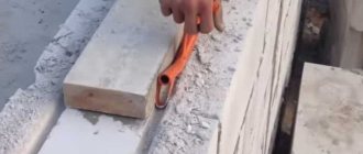
Think about it, if you use a good VVGng-Ls cable, which is hidden in an aerated concrete groove and plastered, does it need corrugation? From a fire safety point of view, corrugation is not needed in this case, but it can be justified if the cable is replaced when it is pulled out of the groove with wire. But it is far from certain that this will work out.
Corrugation must be used if part of the cable is laid in a concrete screed.
The use of corrugation is mandatory for open wiring, and especially when using flammable facing materials such as plastic and wood.
Advantages and disadvantages compared to floor slabs
Wooden beams boast of being lightweight and easy to install. There is a misconception that light wooden floors do not require a reinforcing layer. This is fundamentally wrong.
Important! For aerated concrete walls, regardless of the type of floor, an armored belt is always required!
In the case of wooden floors, its construction will distribute the load from the beams along the entire perimeter of the walls and prevent cracking of aerated concrete from point loads.
The advantages of wooden beams are:
- Environmentally friendly, since wood is a renewable natural material.
- Small mass.
- Low thermal conductivity compared to concrete structures.
- Low price compared to other types of floors.
- Large assortment to choose from.
- Easy to install beams.
Wood also has its downsides:
- Fragility. Sooner or later, even the best floors can begin to rot.
- Low strength - wood will not be able to withstand as much weight as a concrete floor could.
- Flammability (natural materials are highly flammable).
Important! Despite such significant negative qualities, wood is still chosen much more often, and here’s why: special compositions for impregnating wood can extend its service life, protect it from rotting and fire. And low strength is eradicated by using more beams and reducing the laying step. Now let’s look at concrete floors and their disadvantages:
Now let's look at concrete floors and their disadvantages:
- The first and most significant disadvantage is the high cost of concrete flooring. Not only are the floors themselves expensive, but their installation and transportation also requires special equipment (a crane). So you will have to pay a certain amount of money for installation. Wooden floors do not have this disadvantage - you can install them yourself. If the beams are small, then two or three people will be enough. The heavier and more massive they are, the more people will have to be involved.
- High weight. We have already said that installation will require special equipment. You will also need a more expensive foundation.
As you can see, all the disadvantages are related only to the price. To make your final decision, read the article about floor slabs in an aerated concrete house.
Installation of distribution boxes and sockets
Distribution boxes, like sockets, can be recessed into the thickness of aerated concrete, or they can completely protrude on the surface. The recessed version in aerated concrete is more preferable, as it is both more fireproof and more practical.
A large hole in aerated concrete for a socket or distribution box can be made using a screwdriver with a crown. The circles are drilled out and the inside is chopped off with a hammer.
Installation of socket boxes
The height of the sockets is not standardized and everyone selects it based on their own preferences; this time all sockets are located at a height of 25 cm from the finished floor (in the center). After marking - crowning.
Ivanov Kostya
The next step is preparing the entrance to the socket boxes and boxes. Over many years of work, I have come to the conclusion that it is better to do this stage “with a reserve.” Hollow out the entrances wider and deeper. Get over your own laziness. Then it will be easier to install the cable. Well, then a hammer drill plus a drill d 20 mm. The depth of the entrances is almost the same as the depth of the socket boxes. The width of the entrances is greater than the width of the “windows” of the socket boxes. The length of the entrances is equal to the diameter of the socket boxes or slightly longer (7-8 cm).
Clarification: the used models of socket boxes are composite and can be mounted in blocks; for single use, the “ears” are removed.
There are several options for installing socket boxes, both before and after plastering. Kostya prefers before plastering.
- Determines the plaster level using a laser plane builder.
- Pulls a thread along the top of the wall.
- Along the laser plane, he places three self-tapping screws around the socket boxes.
Socket boxes and boxes are fixed with gypsum plaster.
- Dusts the niche (brush, vacuum cleaner).
- Coats the edges of the niche.
- Apply a little mixture to the socket/box so that it penetrates into the recesses.
- He presses the socket boxes with a board to the level of the self-tapping screws (the future plaster layer), and recesses the boxes deeper.
TV sockets in the living room (quantity agreed with the customer). The top row will be covered by the TV itself, the bottom row by the cabinet.