Very often, when performing repair or installation work related to electricity in an apartment, house, garage or country house, it becomes necessary to find zero and phase. This is necessary for the correct connection of sockets, switches, and lighting fixtures. Most people, even if they do not have special technical education, imagine that there are special indicators for this. We will briefly look at this method, and also tell you about another device that no professional electrician can do without. Let's talk about how to determine phase and zero with a multimeter.
Concepts of zero and phase
Before determining phase zero, it would be good to remember a little physics and figure out what these concepts are and why they are found in a socket.
All electrical networks (both domestic and industrial) are divided into two types - with direct and alternating current. From school we remember that current is the movement of electrons in a certain order. With constant current, electrons move in one direction. With alternating current, this direction is constantly changing.
We are more interested in the variable network, which consists of two parts:
- The working phase (as a rule, it is simply called the “phase”). Operating voltage is supplied to it.
- An empty phase, called “zero” in electricity. It is necessary to create a closed network for connecting and operating electrical appliances, and also serves to ground the network.
When we connect devices to a single-phase network, it is not particularly important where exactly the empty or working phase is. But when we install electrical wiring in an apartment and connect it to the general house network, it is necessary to know this.
The difference between zero and phase in the video:
Difference between zero and ground
The consequences of incorrect switching of the neutral and grounding conductors can be different:
- Incorrect operation of electricity meters down or up. Accordingly, in the first case, when the supplier company finds an error, a huge fine may be assessed.
- Incorrect operation of residual current devices and differential circuit breakers: with significant voltage drops, household appliances will constantly burn out.
- Lack of human protection from electric shock. Moreover, the wrong design can be the main cause of the impact.
The article discussed ways to distinguish between neutral and grounding conductors in three-wire systems. They are arranged in order of increasing complexity of actions. Only correct installation of electrical wiring guarantees the correct operation of RCDs, differential circuit breakers and sockets with a grounding circuit. If there is the slightest doubt, it is better to seek help from a qualified specialist who can provide a certificate of repair work.
The simplest ways
There are several ways to find phase and zero. Let's look at them briefly.
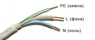
According to the color of the cores
The simplest, but at the same time the most unreliable way, is to determine the phase and zero by the colors of the insulating shells of the conductors. As a rule, the phase conductor is black, brown, gray or white, and the neutral is made blue or blue. To keep you informed, there are also green or yellow-green conductors, which is how protective grounding conductors are designated.
In this case, no instruments are needed; you looked at the color of the wire and determined whether it was phase or zero.
But why is this method the most unreliable? And there is no guarantee that during installation the electricians followed the color coding of the cores and did not mix up anything.
Color coding of wires in the following video:
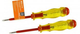
Indicator screwdriver
A more accurate method is to use an indicator screwdriver. It consists of a non-conductive housing and a built-in resistor with an indicator, which is an ordinary neon light bulb.
For example, when connecting a switch, the main thing is not to confuse zero with phase, since this switching device only works to break the phase. Checking with an indicator screwdriver is as follows:
- Turn off the common entrance machine for the apartment.
- Using a knife, strip the cores being tested from the insulating layer by 1 cm. Place them apart at a safe distance to completely eliminate the possibility of contact.
- Apply voltage by turning on the input circuit breaker.
- Use the tip of the screwdriver to touch the exposed conductors. If the indicator window lights up, it means the wire corresponds to the phase wire. The absence of a glow indicates that the wire found is zero.
- Mark the required core with a marker or a piece of electrical tape, then turn off the general circuit breaker again and connect the switching device.
More complex and accurate tests are performed using a multimeter.
Finding the phase using an indicator screwdriver and a multimeter in the video:
How to find which wire is phase
There is no special mode in a digital multimeter to understand exactly where the neutral or phase wire is. By connecting the probes in a certain way, the technician can search for wires based on the information displayed on the display.
Preparing for work
Before finding a phase in the socket with a multimeter, you need to set the operating mode of this device. To do this, the mode indicator is set to the position in which the AC voltage is measured.
Usually you have to choose from several modes. The scale indicates different AC voltage values. Since it is usually 220 volts at the outlet, you should choose the closest value that exceeds it, such as 500 V.
You need to connect the probes correctly. For black, the COM connector is used, and for red, the one next to it.
Checking the functionality of the device
In order to correctly determine the phase with a multimeter, you must first make sure that the measuring device is working. A convenient option for this may be to check the outlet. Using a prepared and configured device, you need to place both probes in the sockets of the socket. The display will show the actual AC voltage value.
Checking the voltage at the outlet
Maintaining polarity in this case when placing wires in sockets is not important. It is important to follow safety regulations during the measurement process. In this case, there should be no contact with those parts from which you could receive an electric shock.
Typically, real indicators are within the range of 215–235 V, but they can only be determined with a working device. Therefore, before checking the phase with a multimeter, you need to know for sure that it is working.
Multimeter. What kind of device is this?
A multimeter (electricians also call it a tester) is a combined device for electrical measurements that combines many functions, the main ones of which are ohmmeter, ammeter, and voltmeter.
These devices are different:
- analog;
- digital;
- portable lungs for some basic measurements;
- complex stationary with a large number of possibilities.
Using a multimeter, you can not only determine ground, zero or phase, but also measure current, voltage, resistance in a section of the circuit, and check the electrical circuit for integrity.
The device consists of a display (or screen) and a switch that can be set to different positions (there are eight sectors around it). At the very top (in the center) there is an “OFF” sector; when the switch is set to this position, it means the device is turned off. To perform voltage measurements, you will need to set the switch to the “ACV” (for alternating voltage) and “DCV” (for direct voltage) sectors.
The multimeter kit includes two more test leads - black and red. The black probe is connected to the lower socket marked “COM”; this connection is permanent and is used when carrying out any measurements. Depending on the measurements, the red probe is inserted into the middle or upper socket.
Why is it important to correctly identify the phase wire
When connecting devices to the network, a working “phase” conductor is used. Voltage is supplied directly to the consumption source. It would be a mistake to connect the receiver to “zero”, because when the circuit is opened (the device is turned off), the network still remains energized. This can be clearly seen if you connect a light bulb switch to the neutral wire. In this case, the cartridge is constantly under voltage. This connection is dangerous when it is necessary to change the lamp or the lampshade itself.
It is important to correctly identify the phase wire.
How to use the device?
Above, we looked at how to find a phase wire using an indicator screwdriver, but it will not be possible to distinguish between zero and ground using such a tool. Then let's learn how to test the wires with a multimeter.
The preparatory stage looks exactly the same as for working with an indicator screwdriver. When the voltage is turned off, strip the ends of the wires and be sure to separate them so as not to provoke accidental contact and a short circuit. Apply voltage, now all further work will be with a multimeter:
- Select on the device the measuring limit of alternating voltage above 220 V. As a rule, there is a mark with a value of 750 V in the “ACV” mode, set the switch to this position.
- The device has three sockets into which test leads are inserted. Let's find among them the one marked with the letter “V” (that is, for measuring voltage). Insert the dipstick into it.
- Touch the probe to the stripped conductors and look at the device screen. If you see a small voltage value (up to 20 V), it means you are touching a phase wire. In the case where there is no reading on the screen, you found zero with a multimeter.
To determine the “ground”, clean a small area on any metal element of home communications (this could be water or heating pipes, radiators).
In this case, we will use two sockets “COM” and “V”, insert the measuring probes into them. Set the device to “ACV” mode, at a value of 200 V.
We have three wires, among them we need to find phase, zero and ground. Touch the stripped area on the pipe or battery with one probe, and touch the conductor with the other. If the screen displays a reading of about 150-220 V, it means you have found a phase wire. For the neutral wire, with similar measurements, the reading fluctuates between 5-10 V; when you touch the ground, nothing will be displayed on the screen.
Mark each core with a marker or electrical tape, and to make sure the measurements taken are correct, now take measurements relative to each other.
Touch the phase and neutral conductors with two probes, a figure within 220 V should appear on the screen. The phase and ground will give a slightly lower reading. And if you touch zero and ground, the screen will show a value from 1 to 10 V.
Checking the three-wire connection
When installing lighting devices, three wires are often used for installation: those related to phase and neutral, as well as grounding. If you compare zero and ground, zero voltage will be found between them.
By determining the phase, you can see that the voltage between the loaded wire and zero is 220 V. If you check the phase wire and ground, the result will be the same. The sequence of connecting the red and black probes to phase and zero during these measurements does not affect anything.
A few rules for using a multimeter
Before determining phase and zero with a multimeter, familiarize yourself with several rules that must be followed when working with the device:
- Never use the multimeter in a damp environment.
- Do not use faulty test leads.
- While taking measurements, do not change the measuring limits and do not rearrange the switch position.
- Do not measure parameters whose value is higher than the upper measuring limit of the device.
How to measure voltage with a multimeter - in the following video:
Pay attention to an important nuance in using a multimeter. The rotary switch should always be initially set to the maximum position to avoid damage to the electronic device. And in the future, if the readings are lower, the switch is moved to lower levels to obtain the most accurate measurements.
Briefly about the main thing
The question of how to determine where the phase is and where the zero is in the wires is quite common and important for many ordinary people, because not in all cases it is necessary to call an electrician. To determine this, you will need minimal skills in using simple measuring instruments, knowledge of the basics of electrical work and following basic safety rules. In fact, it all comes down to knowing the color coding of wiring in electrical cables, purchasing and learning to use an indicator screwdriver or a multimeter (tester).
Multimeter User Mistakes
Chinese multimeters are configured to work even if the probes are placed incorrectly. Be careful not to accidentally break the device. Avoid this method: plug the black wire into the high current measurement connector, and the red wire into its place. If you try to measure the alternating voltage of a high-voltage line, repairs are guaranteed. Wrong ranges must not be used. Avoid trying to measure AC voltage using a DC scale. Checking the phases will be the last time in the life of the multimeter.
The device is damaged by high voltage of alternating polarity. Other things (for example, incorrect polarity of the probes) are not so bad.
We determine the ground with the device
The presence of a ground pin does not mean that this pin is actually grounded. Quite often this wire is not connected anywhere, but only creates an appearance for the user. Competent electricians choose a wire with a stripe for grounding, but if the technician was inexperienced or negligent in this task, then they might not have remembered the color marking. In such situations, the voltage is best measured by touching the water supply or heating pipes. On the grounded wire the voltage level will be less than on the zero wire.
Why is grounding needed?
It would seem that we lived before with two guides, and would continue to live. But the science of electrical engineering does not stand still. And in general, new standards are always written either by leaking a lot of money or by blood. And not following them is at least stupid.
Grounding is necessary to reduce the touch voltage to a value that is safe for humans. Otherwise, any contact with the phase wire - and they happen often - would lead to catastrophic consequences.
On electrical diagrams, grounding is represented by a special symbol ⏚.
The simplest methods for finding phase and zero with a multimeter
A properly organized home grounding circuit eliminates problems. Firstly, PEN insulation is yellow-green in color. It is impossible to confuse it with the brown (red) phase and the blue neutral. It happens that the wiring is laid in violation of the requirements, the colors are mixed up, or missing altogether (aluminum cable). We search for phase with a multimeter using a simple algorithm:
- Let's say an apartment has three wires: phase, neutral, ground.
- We set the multimeter to the AC voltage range of 750 volts and begin testing the wiring in pairs.
- Between the phase and any other wire there will be 230 volts (rms value), the ground-neutral jumper gives approximately 0.
Multimeter
The access panel has at least five wires, three phases. The further process is determined by the imagination of local electricians. Good craftsmen hang stickers A, B, C, indicating the location of the phases. Grounding is yellow-green, neutral is often blue.
Between adjacent phases the voltage is 380 (400) volts. High-rise apartments are sometimes supplied with two phases. Electric stoves with a power above 10 kW try to share consumption. Wiring requirements are reduced. We advise you to immediately take a marker and mark the insulation with the required colors. A house without grounding usually receives two wires: phase, neutral. The substation transformer drives three phases. How many will be in the apartment should be found out.
Problems will begin when there is no wire marking, the phase comes alone. Between dangerous wires the voltage will be... zero!
- Two wires carry a phase, one neutral, they forgot to lay the grounding. There is a round zero between the supply wires; when evaluating the neutral wire, we get 230 volts. The situation looks as if the phase conductors have become neutral and zero. We made a mistake when laying the pipes - what can you do? It is necessary to look for an additional source of support. An indicator screwdriver will do.
- Two wires of one phase, the second pair is grounding, neutral. They will show zero in pairs, crosswise - 230 V. Use a reference point.
There is no probe-screwdriver, with the help of a tester, no matter how you change the wiring, the problem will remain. A reference source that is guaranteed to be grounded is required. Suitable:
- The lightning rod's grounding circuit is often routed along the outer wall of the building, with a strip of steel touching the end of the balcony. Goes vertically down. Grounded, suitable for the chosen purpose with two caveats: grind off the rust layer with a file, carry out the work when the sky is cloudless (beware of lightning).
- The simplest solution is the bathroom faucet. The pipes are now plastic. But inside there is an excellent electrolyte - water with dissolved hardness salts. Touch the black tester probe to the faucet sleeve and take measurements relative to the fulcrum. Use the sidewalls of copper, brass, and aluminum fittings. There would be water.
Indicator screwdriver
- On the site, the steel body of the shield, if not grounded, is connected (shorted) to the zero (neutral) wire. Take measurements relative to the selected reference.
- A gas pipe is a taboo for those who want to ground it; it is at zero potential and comes into contact with the ground. If you find chips of paint, use the accessory for the purpose (it is forbidden to cut off the paint yourself) to identify phases, neutrals, and grounding.
- For the reasons described above, batteries made of cast iron and aluminum have become recognized as a good reference point. The main thing is to ensure close contact. How to check? Call two points of the body. Resistance is units of ohms - the norm. Provided the heating is on. According to regulations, the pump body is grounded, the probability of error is low.
- It is not recommended to use sewer pipes as a reference grounding source. Conductivity conditions are determined by the number of... drains.
Due to the variety of methods and unreliability, it is recommended to conduct tests before starting serious work. Measure the potential between the indicated reference points and the phase of the socket. Is the distance between the landmark and destination point large? We take an extension cord. The power filter for a personal computer is especially good, equipped with a characteristic backlit button. The phase is on the left, the left pin of the plug (depending on which side you turn) is marked with a marker.
Then we call it with a socket (without power, of course), and make a mark on the desired side. Let us explain, you can do without this; it’s better to put aside jokes with electricians. All that remains is to find the phase using the M890S. We set the range above 380 volts (between two phases), and begin to measure the potential difference between the terminals and the shield. We believe that the further algorithm is clear.