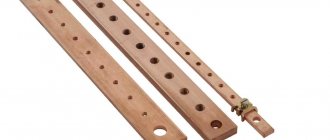
Not only cable management companies, but also other services that carry out excavation work are faced with searching for the location of a cable underground. At first glance, this task looks simple, but there are still certain difficulties. For energy workers, for example, it is important to find not just any power cable, but the specific one they are looking for. But they all emit a signal at the same frequency - 50 Hz. For companies carrying out excavation work, it is easy to find a cable under load, but the difficulty is in finding non-working and temporarily disconnected cables. In this article we will look at this problem and give several ways to solve it.
Finding a broken hidden wiring in a concrete wall
A special device - a locator - will help you find the location of a wire break in a concrete wall. It is a combination of a receiver and an oscillator. This method can be associated with the induction method in searching for cable faults underground.
So, determining the location of the break with a route finder is not difficult. The end of the wire in which there is a break is connected to a generator, which sends pulses of a certain frequency into it. By passing the frame over the place where the wiring is laid, the sound that is formed as a result of the influence of impulses will be clearly audible in the headphones. As soon as the sound disappears, mark this place on the wall - this will be the point of damage to the wire.
A non-contact voltage indicator will also help you find a break in a phase wire. Everything is simple here. We move the device along the wall until the voltage indicator stops lighting. We run the device several times in a circle in this area of the wall to make sure that we have not left the route of the wires. The absence of light on the indicator will indicate the approximate location of the break.
In conclusion, I would like to note that a locator and a non-contact voltage indicator can be used to search for damage to wiring under plaster or under drywall.
Finally, we recommend watching a useful video on finding short circuits in wiring:
So we looked at the most well-known methods for finding the location of cable damage. We hope the information was useful and interesting for you!
We also recommend reading:
How to determine phase, zero and grounding yourself, using improvised means?
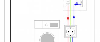
Let's try to figure out how at home, without having complex specialized measuring instruments and electronic devices, you can determine for yourself where the phase is, where the zero is, and where the ground is in the wiring.
Of all the known methods, the simplest determination of phase and zero, we have selected the most, in our opinion, accessible to implementation and at the same time safe. For this reason, in the article you will not see advice on how to find the phase using potatoes or calls for briefly touching the wires with various parts of the body.
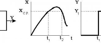
Determining the distance to the location of cable damage underground
Determining the distance to the defect is carried out using one of two methods - reflectometric (using reflectometers) and bridge (using cable bridges). These methods have significant differences.
Cable bridges localize damage based on cable resistance and capacitance. During the measurement, they use auxiliary (known good) conductors or cable pairs, which allows them to measure the resistance (capacitance) of the good pair, compare these readings with similar values on the damaged pair and determine the distance to the defect. During measurements, they most often use a voltage of 180V - 500V, which makes it possible to determine even minor damage to the cable insulation.
Cable reflectometers send a pulse with an amplitude of approximately 20V to the pair (the pulse width is adjusted depending on the length of the line) and the type of damage and the distance to it are determined by the shape and delay of the pulses reflected from inhomogeneities (defects). This method will not allow you to detect minor insulation damage, but it will easily detect mixed-up pairs, parallel taps, Pupin coils, etc.
To increase efficiency, these methods are increasingly being combined in one device. In this version, for example, the IRK-PRO Alfa and KB Svyaz Sova devices are presented. The SideKick Plus and Riser Bond 6000DSL analyzers described above also have such functions.
It should be noted that the accuracy of determining the distance to a defect by the device and the accuracy of localizing damage in the cable are different things. After all, the measured distance still needs to be accurately measured, and this is a very difficult task, taking into account the cable reserves on the couplings, the unevenness of the cable depth, etc. In addition, a large error is introduced by inaccurately entered linear values of resistance and capacitance or the propagation coefficient (and they constantly change during operation).
TELEVISE INSPECTION OF PIPELINES
Teleinspection of pipelines is a service used when it is necessary to diagnose pipes for various purposes. The most in demand is diagnostics of sewer pipes, during which it is possible to determine the location of a broken pipe, the location of a sewer blockage, determine the location of a backfilled well, and determine the condition of a sewer pipe.
Teleinspection of the water supply allows you to accurately detect the location of a water pipe leak (with an accuracy of up to 10 cm). This will minimize excavation work and reduce the financial expenses of the customer.
Even if you are working on your own plot of land, determining the location and depth of underground communications is mandatory.
In the security zone of communications, it is allowed to carry out work manually, without the use of impact tools and with the permission of operating organizations.
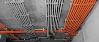
Thermal imaging inspection of premises allows you to determine where buildings freeze, where condensation and mold form over time. Also, thermal imaging allows you to save thermal energy, look for leaks in heating pipes, pipes
hot water supply, place of underfloor heating leaks. Based on the results of the thermal imaging inspection, a report is provided with thermal images and recommendations for correcting the situation.
Damage to cable lines: methods and methods of detection
Most large electrical connections between energy consumers and sources are made using cable lines. Most often this is a system of cables, couplings and fasteners parallel to each other. Damage, even to the smallest extent, is fraught with at least economic losses.
Most common damage
Cable lines can be laid underground or above ground. In this case, the nature of their damage will be similar. Most often the following happens:
- one or more cores may be damaged. In this case, the circuit is made to the ground;
- several wires are damaged with a short circuit to each other;
- grounding cable break;
- gap without grounding;
- the occurrence of a so-called “floating breakdown”, when a short circuit occurs when the voltage increases, after normalization the situation stabilizes;
- the integrity of the insulating layer is damaged.
Any damage requires immediate repair. As power supply patterns are disrupted, the reliability of the entire power supply to end users is called into question. This also affects the technical and economic indicators of the entire network as a whole.
The photo shows that we are dealing with a low-Ohm breakdown; such a place of damage is the easiest to find.
The causes of damage may be:
- In different seasons, soil movement occurs. For example, in the spring, as a result of sudden thawing of individual sections, the lines may experience excessive tension, which leads to rupture;
- violation of supply conditions, in particular overcurrent;
- violations in line laying technology;
- work near lines that violate boundaries;
- lines may be exposed to transit currents.
Briefly about cable line repair
Repair work on cable lines is usually classified into planned and emergency. As for the volume of such work, for the former it is, as a rule, capital, for the latter it is current.
During major works, planned replacement of cable lines, laying of new routes, etc. are carried out. If necessary, repairs and/or upgrades of related equipment are also performed. The latter include ventilation systems and lighting for cable tunnels, as well as pumps for pumping out groundwater. Considering the specifics of planned work, localization of defective areas is not required during their implementation.
The situation is completely different during emergency repairs. In order not to dig up the entire route, you should accurately determine the location of the wire break, insulation breakdown, etc. For this purpose, various methods are used, for which special equipment is used. This will be discussed in detail below.
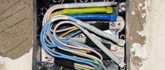
The photo shows a dead-end coupling MT-45. Designed to protect splices of TPP and TPPep cables with a capacity of 10 to 50 pairs with conductors with a diameter of 0.32 to 0.5 mm. The coupling consists only of a polyethylene body in the form of a polyethylene tube, plugged on one side. The method of installing TPP and TPPep cables in the MT-45 coupling consists of connecting the cores and screens of the parallel connected ends of the cables, placing them in the coupling body and then filling the coupling with self-expanding polyurethane sealant VILAD-31. It’s just that it was clearly installed without the use of VILAD-31 sealant, but with the help of an incomprehensible white mass, more like soap or grease. And, of course, blue electrical tape. It is known that in any unclear situation you should use blue electrical tape - this is the “key to success.” The result of such installation of a coupling connection is in front of you.
How to find the location of cable damage?
During operation and at the stage of installation of cable lines laid underground, unexpected mechanical damage to the insulation and current-carrying conductors occurs. This may be due to a violation of normal operating conditions, careless installation work on other communications located a few meters from the installation site and not related to the power supply line. We will further describe how to search for cable damage underground and in the wall, providing existing methods and instruments for detecting the faulty area.
To find the location of the cable line damage, you need to understand the specifics and methodology of the search. The process must be divided into two stages:
- Search for problem areas along the entire length of the line.
- Searching for an accident site on a designated section of the highway.
There are several methods for finding the damaged area:
- Pulse method;
- Loop method;
- Acoustic method;
- Induction method;
- Step voltage method.
Pulse method.
This method involves searching for damage using a reflectometer. The operation of the device is based on sending probing pulses of a certain frequency, which, when encountering an obstacle in their path, are reflected and returned back to the device. That is, the device is located at one end of the power cable, which is very convenient and practical. Tests should be carried out on a completely disconnected line.
Loop method.
This method is applicable provided that at least one wire in the cable remains intact, or another conductor with intact cores lies nearby. To find out the distance to the place of damage using the loop method, you need to measure the DC resistance of the wires with the P333 device. This is a DC measuring bridge. This is one of the first methods invented to find the location of the fault, and it is used exclusively for single-phase and two-phase faults. Gradually they stop using it, due to its labor intensity and large error in measurements.
Acoustic method.
You can find a break in a cable using the acoustic method by creating a discharge at the damage site using a high-voltage pulse generator. At the location of the break or short circuit, sound vibrations of a certain frequency will appear. The quality of listening depends on the type of soil, the distance from the surface to the cable line and the type of damage. A prerequisite for the method to work is to exceed the contact resistance value of 40 ohms.
Step voltage method.
The method is based on passing current generated by a generator through a cable. It creates a potential difference between two points located in the ground, which can be judged by the current leakage at the site of the accident. To find a point with reduced insulation resistance, contact probe probes are installed like this - the first one is exactly above the running conductor, the second one is at an angle of 90, a meter from the first one.
Induction method.
The method very accurately determines the location of the break, but its use is associated with burning the cable. If the transition resistance is high, it is necessary to reduce its value by burning using special devices. The method is based on passing a high-frequency current through the core, which forms an electromagnetic field above the cable line. In places of mechanical damage to the route, passing the receiving frame, the sound will change. Thus, the absence of sound indicates a wire break.
A special device - a locator - will help you find the location of a wire break in a concrete wall. It is a combination of a receiver and an oscillator. This method can be associated with the induction method in searching for cable faults underground.
Intelligent marking of underground utilities
But the main advantage of this technology is not the easier determination of the route location. Markers are not only passive, but also intellectual.
They have internal non-volatile memory based on an RFID chip. The chip is located on a plastic disk.
In some models, all this floats in a propylene glycol solution.
Why does it need to be placed in liquid? Firstly, this allows you to bury markers in frozen soils (without the risk of signal loss).
And secondly, it automatically aligns the disk to a horizontal position, regardless of which side you put the ball in the ground.
When placing this “buoy” you can write down all the necessary information, namely:
- type of communication
- voltage level
- specific name of the coupling or feeder
- cable line owner
- depth
- track turning angle
That is, from now on you simply move the marker finder to a given point, and instantly, without searching for drawings and documentation, directly “in the field” you receive all the information you are interested in about the cable.
Moreover, using the same marker finder, all previously recorded data can be edited and changed, which is called in real time. To do this, place the locator above the marker in the ground, select the appropriate menu items and enter all changes.
After all, within 50 years both the owner of the line and the feeder number may change. You won’t dig up a red buoy to add new data to it.
Editing occurs directly through the marker finder, even without connecting to a laptop.
An intellectual marker acts as a kind of “eternal” identification mark, but not externally, but underground. At the same time, vandals will never be able to purposefully damage it.
Methods for finding the location of cable damage
The following methods have been developed and successfully used to search for damage sites.
Pulse method
The pulse method is excluded from use in case of floating breakdowns due to the fact that the cause of such damage is high humidity; therefore, the conductor resistance exceeds 150 Ohms, and this is unacceptable for this method.
The check is carried out in accordance with the instructions provided on how to find the location of the damage, using an IKL-5 or IKL-4 meter by introducing a pulse through alternating current to the fault area and receiving a response signal. The device measures the time between the period of delivery and the return of the pulse.
Acoustic method
The acoustic method involves the use of a receiver and an electric generator of powerful shock pulses. The generator capacitor is connected to the cable, and when the spark gap is triggered, the voltage in the line creates an electromagnetic wave, and strong penetration occurs, accompanied by a click in the fault area. The operator detects clicks using an acoustic device.
The sound propagation zone ranges from two to fifteen meters. The point of cable failure is determined by the presence of the loudest possible sound.
Loop method
Faults are determined by comparing the resistances of the broken and intact cable cores using the loop method. The procedure for searching for damage in this case requires the formation of a bridge of type R 334 or R 333 from the cable, and the presence of an MVU-49 resistance bridge is also required.
It is used if one cable core is not damaged; if all cores are faulty, it is recommended to use an undamaged core of a nearby cable channel.
The good and damaged cores are connected on one side of the cable in a loop. A bridge is installed on the opposite side of the cable to regulate electrical resistance. Measurements are taken and, using resistance ratio formulas, the distance to the fault location is established.
The disadvantage of this method is the inaccuracy of determining the location of the fault and the huge time costs.
Induction method
Let us now consider how to determine the area of cable damage using the induction method, which is more accurate and gives a chance to identify the fault section directly in the cable line; the error of this method does not exceed 50 centimeters.
The use of the induction method is permissible if, at the location of the fault, the transition resistance in the cable line is no more than twenty to fifty ohms.
The content of the method is to capture and fix over the cable channel oscillations of the electromagnetic field formed by passing electricity through the faulty conductor with a sound frequency of 800 to 1000 Hz. The operator moves along the cable route and, using an antenna, amplifier and headphones, determines the nature of the transmission of the electromagnetic field. The sound increases noticeably at the point of failure and loses strength at a distance of 50 centimeters from the point of breakdown.
Wire satellite
Someone may rightly point out why I need all this complexity; I can find my cable anyway by connecting the generator to the corresponding cores.
What if we are talking about communications without metal components? For example, polyethylene gas pipeline or fiber optic communication lines.
In such a situation, a satellite wire laid in parallel is usually used. Although this is not regulated in any way by current industry standards, it is widely used.
Most often, the cheapest wire of the PV 1*2.5 or PV 1*4 brand is used as a conductor.
At the same time, if we objectively compare all costs, and especially service life, then markers outright outperform such wires in all respects. Here you can familiarize yourself with already implemented projects and reviews on this technology.