Every house has switches, and more than one. We have all become accustomed to these small devices and consider them an integral part of our everyday life. It may seem that they are all designed the same and are extremely easy to install. However, this is not at all true - the devices are very diverse.
Agree, it would be a good idea for any home craftsman to know which model is best to use and how to install the light switch so that the device works flawlessly.
The article is devoted to solving these questions. We will outline the operational features of different switches, and also provide detailed instructions for installing open, hidden and walk-through models.
Wiring: open or hidden option
Despite the fact that installing a switch may seem like a very simple matter, there are a large number of nuances that a novice electrician must know.
First you need to decide on the type of wiring.
Open wiring is still used in everyday life. It is especially loved by designers who create interiors in retro or loft style.
Electrical wiring is an essential element present in every home.
There are two types of it:
- Open . The wires are laid on top of the wall. They can be secured with decorative rollers or covered with plastic cable ducts.
- Hidden . The wire is laid inside the wall. To do this, channels are cut into its surface into which the cable is laid. After installation, the grooves are sealed with mortar.
Each type of wiring uses a different type of switch. For an open system, choose overhead models that are placed directly on the wall. They are easily recognizable because they are very visible on the surface.
This type of switch was the first to appear and has changed little over the past decades. For closed wiring, internal or built-in models are used.
Image gallery
Photo from
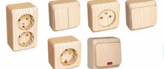
Switch-socket block for open wiring
Benefits of installing external switches
Switches for hidden electrical wiring
Disadvantages of hidden wiring switches
They are installed in a recess that is previously prepared in the wall. The dimensions of the hole are selected depending on the dimensions of the switch. It is attached inside the recess using special spacer legs.
There is another type of built-in devices - with mounting plates. This option is more convenient to install. After installation, the internal switches practically do not protrude above the wall plane.
Why “phase” and not “zero”?
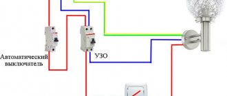
We are close to answering the question of whether zero or phase goes to the switch and why. The switch opens the section of the network in which the light bulb operates. And in simple switches it interrupts only one of the wires that passes through it. The second wire remains powered directly to the lamp. If in your case a zero is passed through the switch, then a phase is permanently connected directly to the chandelier, which means that even with a simple replacement of the light bulb, the device can shock you.
If the switch opens the phase, then zero goes directly to the chandelier from the box. This means that if the switch is in the open (off) state, the phase is no longer supplied to the device, since it is interrupted by the switch itself, and replacing the lamp will be safe.
Switch wire switching method
Before you begin installing the switch, you need to know that the internal fastenings of the wires in the device may be different. Two switching methods are used.
Screw type clamp
The screw type contact is tightened with a screwdriver. First, approximately 2 cm of the wire is cleared of insulation, then it is located under the terminal and secured. It is extremely important that not a millimeter of insulation remains under the terminal, otherwise it will begin to melt, which is very dangerous.
Screw-type clamps are optimally used for aluminum wires, which tend to heat up and become deformed. To restore functionality, it will be enough to tighten the contact (+)
This connection is especially good for aluminum wires. They heat up during operation, which eventually leads to deformation. In this case, the contact begins to heat up and spark.
To solve the problem, it will be enough to tighten the screw. The wires, sandwiched between two flat contact plates, will “fall into place” and the device will operate without heating or sparking.
Non-screw type clamp
Represents contact with the pressure plate. Equipped with a special button that adjusts the position of the plate. The wire is stripped of 1 cm of insulation, after which it is inserted into the contact hole and clamped. The whole procedure is very quick and easy.
The non-screw clamp is extremely easy to install, which is why experts recommend that novice electricians work with terminals of this type
The design of the terminal ensures high reliability of the resulting connection. Non-screw terminals are best used for copper wiring.
It must be admitted that screw and non-screw clamps provide approximately the same reliability and quality of connections. However, the second option is easier to install. It is this that experienced specialists recommend using for novice electricians.
We outline an action plan
Step-by-step instructions for installing a switch depend on the amount of work required and generally consist of five steps:
- Preparation for installation;
- Carrying out the required construction work
- Switch installation;
- Network connection;
- Functionality check.
For clarity, the algorithm of actions of each stage will be accompanied by a number of photographs and detailed connection diagrams.
Main types of switches
The time has long passed when all models were approximately the same and differed only in appearance. Today, the manufacturer produces a variety of types of switches. Based on the type of switching on/off, all of them can be divided into several groups.
No. 1: Keyboard type devices
Very simple and reliable design. The basis of the device is a swinging mechanism, which is pressed by a spring. When you press a key, it closes a contact, which turns the electrical device on or off.
For the convenience of consumers, one, two and three-key switches are available. This makes it possible to control not only one, but several lamps at once.
No. 2: Switches or changeover switches
Externally, these devices are indistinguishable from their keyboard counterparts, but their operating principle is completely different. When you press a key, the devices open one electrical circuit and transfer the contact to another.
This allows simultaneous control of lighting from two, three or even more places. Complex circuits that involve more than two switches are supplemented with crossover elements.
Dimmers not only turn on the lighting, but also regulate its intensity. There are also multifunctional types of devices that can simulate presence, operate on a timer, and much more.
#3: Dimmers or Light Intensity Controllers
A switch that allows you to adjust the lighting intensity. The external panel of such a device is equipped with keys, a rotating button or infrared sensors.
The latter option assumes that the device can receive signals from the remote control. Complex dimmers can perform several functions: activate dimming mode, simulate presence, turn off lights at a specified time.
The criteria for choosing a dimmable switch are described in this article.
No. 4: Switches with built-in motion sensor
Devices react to movement. The appearance of people is registered by a sensor that activates the lighting and turns it off if there is no movement. To operate the switch, an infrared sensor is used, which is capable of analyzing the intensity of infrared radiation and distinguishing a person from other objects.
Multifunctional switches with a motion sensor can not only turn on lighting fixtures, but also activate video cameras, sirens, etc.
No. 5: Touch-type devices
Turn the lighting off/on by lightly touching the sensor. Varieties are available that are triggered when a hand is passed near their body. The main difference between touch switches and traditional analogues is the presence of microcircuits.
This eliminates the risk of a short circuit, which significantly increases the service life of both the switch itself and the lighting fixture.
There are many types of switches. Illuminated models are designed to facilitate orientation in dark rooms
The essence of electricity
Let's try to explain the work of electricity in the most accessible words. We also know from physics lessons that the very essence of electricity is such that the phase always tends to discharge to zero. It is between the electricity-carrying and grounding flow that various types of devices are included in the circuit. Then a discharge occurs in them, forcing them to work.
In particular, this is how the filament or diode circuit in a lighting lamp works. The filament or diode circuit has its own resistance, which is balanced so that the lamps, when the network is closed through them, do not burn out, but begin to glow. And in essence, it doesn’t matter which wire goes to the switch - zero or phase, if zero is supplied to the lamp itself from one contact and phase from the other, it will work anyway. This will not affect the performance of the device in any way. This is only for security reasons.
How to choose the “right” place for the switch
Choosing a place to install the switch is a personal matter for each owner. However, there is a set of industry requirements that regulate this issue. This is due to the fact that laying electrical wiring is quite an expensive undertaking and redoing it every time is expensive and too troublesome.
Experts recommend installing all switches in the house at the same height and the switching position should be common for all.
The devices are usually mounted at the height of door handles, which correlates well with the development of muscle memory. Thus, when entering a room, a person presses a key automatically, without even noticing it.
Another important point: the switch in the room must be positioned so that there is a distance of about 15-20 cm between it and the doorway. This way a person can grab the door handle with one hand and press the key with the other.
For living rooms, it is customary to install switches only indoors. For common areas, such as bathrooms, closets or corridors, switches located outside the room are most often used.
If there are small children in the house, you should not “lift” the switches up. The restless period when the baby will “play around” with the light will pass very quickly, and the inconvenience from the location of the switches will remain for a long time.
The design of the switch is extremely simple. Its main elements: mechanism on the mounting plate, keys and decorative protective panel
What colors should the wires have in the electrical wiring of an apartment?
Any conductor purchased for electrical wiring must contain a core with a blue (blue) braid. It is this that is recommended to be used in the network as a neutral wire. If the apartment has a third wire - direct grounding, it is recommended to run a yellow-green wire on it. All other wires (it can be white, brown, black, etc.) are used as phase-carrying wires. So to the question whether the switch breaks phase or zero, the answer will be unequivocal - phase, and this core will not be blue or green.
If the wires in your apartment are mixed up, it means that the installation of electrical wiring in it was not carried out by professionals and, most likely, it has already undergone repairs.
Surface Mount Switch Installation Procedure
Such devices are used for open wiring and where for some reason it is impossible to make a hidden connection.
Let's look at the installation procedure using the example of a fully factory-assembled single-key switch. To connect it, you need to turn off the power supply to the apartment, and then perform the following operations sequentially.
Step 1: Disassemble the device
We take a slotted screwdriver, very carefully lift the device key and remove it. After this, just as carefully, trying not to damage it, remove the protective decorative cover. All we have to do is disconnect the working mechanism from the socket plate. Let's carry out this operation.
Step 2: Design the installation location
The manufacturer must make holes on the base plate for securing the device. They need to be marked on the wall. To do this, take the socket box, apply it to the surface and mark the line of the top edge with a pencil.
Using a level, we check that it is horizontal, otherwise we will not be able to install the switch evenly. After this, we again apply the plate to the wall and mark the attachment points.
Step 3: Install the socket plate
Further actions depend on the material from which the wall is made. If it is soft wood, fasten the base with galvanized screws. If the base is made of harder materials, you will have to drill holes in it.
We try to do all the work accurately so that we don’t have to make additional holes. We securely fasten the plate to the wall.
The last stage of mounting a surface-mounted switch is the installation of a protective decorative case and a key. After this, the device can be used
Step 4: Connect the wires
We determine the type of contact switching and cut and strip the wires in strict accordance with it. Be sure to remove all insulation so that it does not subsequently melt and cause problems with the operation of the device.
We check that the wires reach the terminals as accurately as possible; it is undesirable for excess wires to remain. In accordance with the markings and color of the wires, we connect them to the required contacts.
Step 5: Assembling the device
First we need to make sure that the wires are connected correctly, for which we test them with a multimeter screwdriver or other device. Having found out that everything is assembled correctly, we take the switch mechanism and install it in place.
Then we return the protective decorative cover and, last of all, snap the key into place. We check the operation of the device.
Rules for safe work performance
The most important guarantee of safety when working in an electrical installation is to perform all actions with the voltage turned off. To do this, you need to turn off the voltage in the entire lighting system. It’s even better to create a visible gap - disconnect the outgoing wire from the power supply during installation. This will eliminate the possibility of accidental voltage supply by unauthorized persons. Power can only be supplied for a short period of time to check the phasing. The use of insulated hand tools (nippers, screwdrivers), dielectric mats, and dielectric gloves will also increase safety during work. Following these simple rules will help you avoid unpleasant (or even tragic) consequences and will subsequently allow you to operate the light switch comfortably for many years.
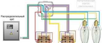
Connecting a pass-through switch
To correctly install a rocker light switch, you need to accurately understand the principle of its operation. In the simplest case, the device, when you press a key, will open one circuit and close another.
On the back of switches of this type, the manufacturer always shows a diagram of the device’s operation. Let's consider the installation procedure for the simplest single-key pass-through switch.
For installation, we will need a three-core cable, each of the cores of which will have a factory color marking. Be sure to turn off the electricity before starting work.
We sequentially perform the following operations:
- On the pass-through switch we determine the common terminal.
- We bring out the phase conductor to the switch that is located closer to the distribution box and connect it to the common terminal.
- We connect the remaining two wires to the output terminals of the pass-through switch. At the same time, be sure to remember what color wire is connected to which terminal.
- In the distribution box we connect the phase from the lamp with the phase wire of the second pass-through switch.
- Guided by the color of the braid, we connect the two remaining wires with wires of similar color from the first switch.
Afterwards, we find the grounding and neutral wires in the distribution box and connect them with similar cables going to the lamp.
The figure shows the installation diagram of a simple single-key rocker switch (+)
We carry out all the twisting very carefully, if necessary we tin it and properly insulate all exposed sections of the wires. It is strongly not recommended to connect copper and aluminum wires together.
Next, we proceed to install the pass-through switch, which will be similar to the procedures described above. We disassemble the device, connect the wires to it in accordance with the diagram, put the mechanism in place and fix it.
Reinstall the protective panel and key. Now you can start checking the functionality of the assembled circuit. Make sure that both switches can control the lamp. That is, each device can turn the lamp off or on, regardless of the position of the other device.
Each switching of the pass-through switch must turn the lamp off/on. If not, you should look for and correct the error.
A more complex variation of a single-key rocker switch is a two-key device. Essentially, these are two single transition devices assembled in a common housing.
This design allows you to control several lamps at once. The device is connected with a three or six-wire wire.
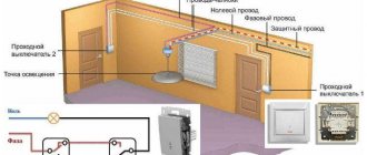
Lighting control circuit for a single-lamp chandelier, lamp, sconce
This scheme can be called the simplest. To turn on/off the lamp, simply install a switch on the phase wire of the lamp's power supply.
Illuminated switch
Everyone is familiar with convenient backlit switches. For some manufacturers, switch lighting is installed separately (wiring with a diode). The backlight is connected as follows. However, in practice, such a concept for installing a single-key switch cannot be implemented everywhere. For example, to control the operation of a sconce with a switch on the power cable.
Socket for stove
There are many types of sockets for electric stoves, but one thing can be said about all of them - very often the installed socket prevents you from moving the stove close to the wall. This applies to both conventional stoves and built-in ovens. To avoid getting into trouble, when installing the wiring, I provide a space in the wall for the installation box behind the stove. A recess is selected in the wall and a junction box with a small supply of wire is installed. Now, regardless of the type, the plug from the stove will stick out from the wall much less and will not interfere with installation. If the wall is lined with plasterboard, installation is simplified - the plaster is cut to size, the box is screwed to the wall under the plaster. In this option, you can easily mount a power socket or make a connection with a terminal block.
Socket boxes
Modern electrics involve installing socket boxes for all sockets, switches and other installation products (TV, Internet, telephone, floor heating thermostat). Long gone are the days when a hole in the wall vaguely resembling a circle was enough for installation. When repairing and reconstructing electrical wiring, it is strongly recommended to install socket boxes. In Soviet times, there were metal socket boxes - if possible, they should be removed and new ones installed; they are not very suitable for modern installation components.
Of course, new sockets and switches can be installed in a round hole in the wall without a socket box, but this is not a reliable installation; the whole thing quickly gets loose.
New socket boxes should be installed so that the holes for the screws are clearly horizontal or vertical. Otherwise, difficulties will certainly arise with the even installation of sockets. Rows of several socket boxes should form a clear horizontal or vertical line, then all modules will clearly fit into a common frame.
The distance between adjacent socket boxes must also be certain. Normal socket boxes have special protrusions on the sides for grouping; if there are none, it is better to install these socket boxes in single places.
For even installation of the socket boxes, after all the grooving operations, all lines (axes) of each socket box are marked on the wall. The distance between the centers of adjacent socket boxes should be 71 mm; the greater the number of socket boxes in a row (no more than five), the more accurate this interval should be.
In concrete, brick and other hard materials, socket boxes are secured with gypsum putty, plaster or alabaster. Alabaster is convenient because it hardens very quickly and does not allow the socket to “float.”
Two fundamentally different types of sockets
One of the most important design features is modularity - you either have modularity or you don't. Simply put, modularity is the ability to place several electrical points in one common frame, housing. It doesn’t matter at all which electrical point will be located next to the neighboring one. This could be a socket and a switch, two sockets and two switches, a switch and a heated floor thermostat. The configuration of installation locations can be different, the main thing is that they are all modular and from the same manufacturer, often even from the same collection. That is why it is recommended to buy all electrical installation products at once.
Typical representatives of modular sockets, all sockets are located in a common frame. Any of the seats can easily accommodate a one, two or three-key switch (if any are available in a particular collection).
Sockets and switches that are not modular can, of course, be installed side by side in several pieces, but outwardly they will not fit into the aesthetic appearance. Moreover, if several socket boxes are installed in the wall in a row, according to modern standards, non-modular sockets simply will not fit. Each outlet will cover with its housing part of the space of the adjacent one.
However, simple sockets are cheaper and work quite well when installed alone. Aesthetic appearance is another matter - high-quality, expensive electrical equipment is usually made modular. Sometimes, simple sockets are indispensable, for example, when you need to put a double socket in one socket - such models of simple sockets are quite common.
Double sockets in one socket box are quite common among non-modular installation products. They are quite practical, but such sockets cannot be combined into a common frame with other installation products, for example with a switch.
It is quite easy to distinguish a simple socket/switch from a modular one - in a simple one, the middle and edges of the cover are one whole, while in modular ones the middle and frame are clearly distinguishable, and often there is a third, middle frame.
For modular electrical outlets, evenly installed rows of socket boxes are important; the rows can be either horizontal or vertical. The distance between the socket boxes is also important - usually they have the ability to dock with each other, the distance is specified by the manufacturer.