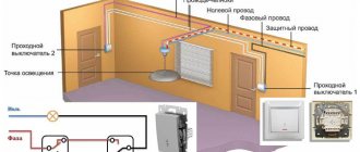
Connection diagram for pass-through switch widely used in modern buildings with large spaces. This is typical for cases when it is necessary to turn a light bulb on and off, for example, from remote points located in different parts of the apartment.
Thanks to this combination, it is possible to turn on the lighting with one of the devices when entering a room, and with the help of a second device it will be possible to turn off the same lighting when leaving the other end of the room.
Principle of operation
Walk-through switches are no different in appearance from conventional key switches - their design and principle of operation have their own specifics. The main differences between these switching devices are the number and order of connection of the switching contacts.
Please note: When a conventional single light switch is triggered, the phase circuit in which the switching device is connected is simply closed or opened.
When operating 2-pass switches, the order of breaking and closing the chain supplying phase voltage to the lighting device is more complex and branched. During the switching process, two such switches, the diagram of which is discussed below, close one of the connecting lines while simultaneously opening the other.
Due to this, it is possible to implement the principle of separate control of the same lighting device from two places located at a considerable distance from one another. The most typical example of such an organization is the location of switches at opposite ends of a long corridor. This feature ultimately determines the specifics of installation of walk-through switches within the boundaries of a particular inhabited room.
Connection diagrams
The order of connecting devices included in the remote control system is determined by the switching features of the pass-through switches. Let's take a closer look at the principle of their operation.
Electrical diagram
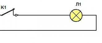
The operating procedure of the system under consideration is most conveniently explained if we use the electrical diagram for connecting a single-key pass-through switch.
According to this figure, the pass-through switches are connected by two linear conductors connecting the switching points. In this case, their changeover contacts are initially in opposite positions and connected to unused linear wires.
Upon entering the room, the switch plate of the first device is moved to a position in which the power supply circuit of the illuminator is closed. As a result of this, it turns on. At the exit of the room, the key of the second single-key switch is switched to the “Off” position, so that the previously formed power circuit is interrupted and the light goes out.
Experts advise, even before connecting the pass-through switches, the diagram of which is discussed above, to specifically provide two points for their placement in the apartment.
Installation diagram with distribution box
An installation or working diagram for connecting a pass-through switch with a detailed drawing of all the conductors used in it allows you to visualize the general order of formation of connections. In addition, it helps to understand how the distribution (connection) boxes located in the apartment relate to this. The electrical connection diagram for all of the listed elements is shown in the photo below.
By using a standard distribution box, indicated in the figure as a circle, it is possible to electrically disconnect the individual conductors of a system of two switching devices. In this diagram, blue and yellow colors show the conductors that supply zero and phase to the light bulb, respectively, and black colors show the internal switching chains.
We invite you to watch a video on how to connect two pass-through switches without a distribution box:
Marking on the switch body
The part of the switch where the contacts are located usually has special markings indicating the characteristics of the switching product. At a minimum, these are voltage and current ratings, as well as IP ratings and wire terminal designations.
If the switch is selected for circuits with fluorescent lamps, then its marking must contain the letters “X” or “AX” (on ordinary ones there is only “A”)
When the light in fluorescent lamps is turned on, a sharp surge of inrush current occurs in the circuit. If LED or incandescent light bulbs are used, then this jump is not so large.
Otherwise, the switch must be designed for such high loads, otherwise there is a risk of burning the contacts in its terminals. This is why it is so important to choose special switches for fluorescent electric lamps.
For installation in a bedroom or hallway, a switch with IP03 is quite suitable. For bathrooms, it is better to raise the second digit to 4 or 5. And if the switching product is installed outdoors, then the degree of protection should be at least IP55.
Contact clamps for electrical wires on the switch can be:
- screw with and without a pressure plate;
- screwless spring.
The former are more reliable, while the latter greatly simplify electrical installations. Moreover, the best option is screw clamps with an addition in the form of a pressure plate. When tightened, they do not destroy the wire core with the tip of the screw.
According to GOST requirements, if the conductor has a cross-section of up to 1.5 mm, then it is unacceptable to use a screw clamp in which the end of the screw is rotated along the core to connect it to the switch
Also in the switch markings there are terminal designations:
- “N” – for the neutral working conductor.
- “L” – for conductor with phase.
- “EARTH” – for the neutral protective conductor to be grounded.
Plus, usually using “I” and “O” the position of the key in the “ON” and “OFF” modes is indicated. Manufacturer logos and product names may also be present on the case.
Lighting control from three places or more
There are often situations when in large residential premises there is a need to control lighting from several points at once. To create a multi-point control system that allows you to turn on and off lights from 3 places at the same time, installing pass-through switches alone is usually not enough.
For these purposes, you will need to integrate one more element into the circuit - cross switch , which is connected at the break of the two-core wire (that is, between pass-through devices).
If in earlier times the permissibility of installing such schemes was determined mainly by the layout of the premises, today they are found almost everywhere. Installing pass-through switches of this type is not an easy task. First of all, you need to familiarize yourself with the principle of its operation.
Operating principle of a cross switch (switch)
The design of the switch provides for the presence of four contacts, of which two are connected to the terminals of one switch and two more to the second device.
Please note: The main difference between crossover switches and pass-through switches is that they can only be used in conjunction with pass-through switches.
When switched on in this way, these devices perform special (transit) functions, since they are to a certain extent transitional.
You can clearly see the principle of operation of the cross switch in the GIF picture below.
Connection diagram for pass-through switch for control from 3 places
A schematic diagram of connecting a 2-way switch and one crossover switch is shown in the figure.
It clearly shows that a cross switch is installed between the two pass-through switches, acting as a kind of transit node.
Below is a wiring diagram for a pass-through switch, which shows the connections of all elements of the electrical lighting control chain in the distribution box.
The video that we have posted below will undoubtedly help you assemble a wiring diagram for three switches in a junction box.
Connection diagram for pass-through switch for control from 4 places
For four control points, you will need to use the complex wiring diagram shown in the figure below. This kit uses not only two pass-through switches, but also a pair of cross-type switches.
When considering the option of controlling a lamp from 4 places at once, two cross switching devices will be required.
If there are several lighting groups in a given room, preference should be given to two-key cross-type switches. Passage systems installed in this way significantly simplify the lighting control procedure.
Connection diagram for pass-through switch for control from 5 places
To control lighting from five points, you will need two pass-through switches and three cross switches. The connection diagram will look like this:
Lighting control circuit from five places or more using pass-through and cross switches (1 and 2 - pass-through, x1, x2 ... xn - cross)
What does a pass-through switch look like and work?
If we talk about the front side, the only difference is: a barely noticeable arrow on the up and down key.
What does a single-key pass-through switch look like?
If we talk about the electrical circuit, everything is also simple: in ordinary switches there are only two contacts, in pass-through switches (also called changeover contacts) there are three contacts, two of which are common. There are always two or more such devices in the circuit, and they are switched using these common wires.
The difference is in the number of contacts
The operating principle is simple. By changing the position of the key, the input is connected to one of the outputs. That is, these devices have only two working positions:
- input connected to output 1;
- input is connected to output 2.
There are no other intermediate provisions. Thanks to this, everything works. Because the contact switches from one position to another, electricians believe it is more correct to call them “switches.” So a pass-through switch is also this device.
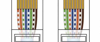
In order not to rely on the presence or absence of arrows on the keys, you need to inspect the contact part. Branded products should have a diagram on them that allows you to understand what type of equipment you have in your hands. It is definitely found on products from Lezard, Legrand, and Viko. They are often absent on Chinese copies.
This is what the changeover switch looks like from the rear
If there is no such diagram, look at the terminals (copper contacts in the holes): there should be three of them. But not always on inexpensive copies the terminal that stands alone is the input. They are often confused. To find where the common contact is located, you need to ring the contacts with each other at different key positions. This must be done, otherwise nothing will work, and the device itself may burn out.
You will need a tester or multimeter. If you have a multimeter, set it to sound mode - it beeps when there is contact. If you have a pointer tester, ring for a short circuit. Place the probe on one of the contacts, find which of the two it rings with (the device beeps or the arrow shows a short circuit - it deviates to the right all the way). Without changing the position of the probes, change the position of the key. If the short circuit is missing, one of these two is common. Now all that remains is to check which one. Without switching the key, move one of the probes to another contact. If there is a short circuit, then the contact from which the probe was not moved is the common one (this is the input).
It may become clearer if you watch a video on how to find the input (common contact) for a pass-through switch.
How to connect the hob is written here.
Electronic devices
To control their lighting fixtures from many points, the apartment owner can use both key switches and electronic devices.
One such device is KillerSwitch, a Russian-made device for turning lights on and off from different locations.
This electronic device operates in two modes depending on the type of switches:
- Using classic key or push-button switches with latching without backlight. In this case, you can connect from 1 to 3 switches.
- Using key or push-button switches without fixation.
To change the operating mode of the device, you must remove or install the jumper.
Connection diagrams for the KillerSwitch electronic device
Connection diagram for latching switches
Connection diagram for momentary switches
We bring to your attention a video about the connection procedure and operation of the KillerSwitch electronic device.
These systems of many switched devices (for all their apparent convenience) raise doubts about their reliability to an even greater extent. Even if they are turned on correctly and handled with care, they are characterized by the following disadvantages:
- relatively high cost;
- relatively low reliability;
- possibility of false positives;
- difficulty of maintenance and repair.
That is why connecting pass-through and cross switches to control lighting from several places is the best option for using the principle of multipoint control.
Installation method
Wiring installation is a rather complex process; it is necessary to use only specialized objects and devices to connect wires.
- For example, a terminal box is perfect for a large number of changeover type devices.
- You can use the simple twisting method only if no more than 2 devices of this type are installed.
- However, even in this case, after twisting, the wires will need to be carefully soldered, and then wrapped with insulating tape for reliability.
- Next, they, as in any other cases, are placed in mounting boxes.
Sensory Modifications
Currently, owners of apartments and private houses are increasingly using touch switches to furnish their premises. The line of this type of product also includes touch-sensitive pass-through switches .
The devices not only increase the level of comfort, but are also stylish design elements.
Touch switches in the interior
Below we provide some connection diagrams for touch pass-through switches.
Connection diagram for two pass-through touch switches
Connection diagram for three pass-through touch switches
To learn how to connect and sync pass-through touch switches, you can watch the video below.
conclusions
When analyzing all the connection diagrams for pass-through switches discussed in this review, the following can be noted:
- The simplest of these systems provide undeniable advantages and do not have any noticeable disadvantages (this applies to a pass-through switch with one key, in particular).
- More complex complexes, which also include crossover devices, may not be as effective as they seem.
- This is explained by the fact that even taking into account the ease of management, their use is associated with high costs and a decrease in the reliability of the entire system as a whole.
- When installing switching circuits in which switches are arranged in a daisy chain, you will need to carefully monitor the order of switching in order to prevent critical errors.
- This should also be attributed to the disadvantages of complex kits that include crossover switches.
In the final part of the review, we note that when arranging such systems one has to deal with certain difficulties in laying linear conductors. When choosing an installation method, there are options for hiding them deep in the walls or using special cable channels for this. If the owner of a private house plans to “hide” the wires deep into the walls, he should worry about this in advance (preferably at the stage of developing the construction project).
Wire placement
The placement of wires must be in accordance with all current regulations. First of all, you need to decide where exactly they will pass, from above or below.
In both cases, you need to deviate from the floor and ceiling surfaces by at least 15 cm. This is done so that floor and ceiling skirting boards and other interior elements do not complicate access to the wiring.
At this distance, recesses for the wires are grooved in the wall, this is the case if there is only rough finishing in the room. This way you can hide the wires in the wall. Afterwards, boxes must be placed in the recesses made, inside which the wires will be placed.
In the event that the wiring is carried out after repairs, then you also need to use boxes, but you need to select them with an appearance that will be combined with the interior of the room, because otherwise the boxes will stand out strongly against the general background, spoiling the whole look.