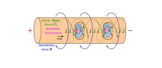
The appearance of electric current occurs when the circuit is closed, when a potential difference occurs at the terminals. The movement of free electrons in a conductor is carried out under the influence of an electric field. As they move, electrons collide with atoms and partially transfer their accumulated energy to them. This leads to a decrease in their speed of movement. Subsequently, under the influence of the electric field, the speed of electron movement increases again. The result of resistance is heating of the conductor through which current flows. There are different ways to calculate this value, including the resistivity formula, which is used for materials with individual physical properties.
Experiments to establish the values on which resistance depends
The reason for electrical resistance lies in the interaction of electrons with ions of the metal crystal lattice. It is logical to assume that the resistance will depend on the type of substance from which it consists. We will also assume that there is some dependence on the length of the conductor and its cross-sectional area .
Now let's conduct experiments that will confirm or refute our assumptions.
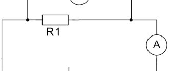
Let's assemble an electrical circuit from a current source, a switch, an ammeter and a rheostat. A rheostat is a device that allows us to change the current strength in a circuit. You will learn more about it in a separate lesson.
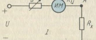
We will alternately connect various conductors to this circuit. We will connect a voltmeter to them in parallel (Figure 1).
Figure 1. Determination of the dependence of the resistance of a conductor on its size and type of substance
What conductors will we connect to the circuit?
There can be a huge number of options. We will look at the following:
- Nickel wires of the same thickness (same cross-sectional area), but different lengths
- The same nickel wires, but now the same length and different thicknesses (with different cross-sectional areas)
- Nickel and nichrome wires of the same length and thickness
Each time we will record the current values in the circuit as shown by the ammeter. The voltmeter will give us the voltage readings at the ends of each conductor.
Next, using Ohm's law for a section of the circuit, we can calculate the resistance of each conductor using the formula $I = \frac{U}{R}$.
What is electrical resistance
Positioned as the resistance of some element that serves as a conductor. It has a unit length, an indicator of cross-sectional area. This is the physical meaning. Electrical resistance is a conductor parameter based on:
- material structure;
- form parameter;
- product dimensions.
Experimental results
What conclusions can we draw after all the calculations?
- Of two nickel wires of the same thickness, longer wire has greater resistance.
- The nickel wire with a smaller cross-section a greater resistance . In this case, the length of the wires was the same
- Nickelin and nichrome wires have different resistances with the same dimensions
Conductor resistance
Based on their resistance, bodies are divided into three classes: conductors, non-conductors (insulators) and semiconductors . This division is arbitrary, since in nature there are no absolute conductors and absolute insulators.
Further, a conductor should be understood as a metal body.
The resistance of the conductor depends on the following factors: type of material, size, impurities, deformation, temperature.
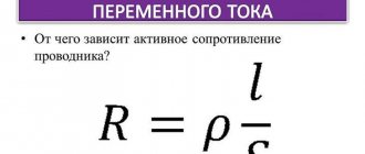
The resistance of a homogeneous conductor of length l and cross-section S is (at a given temperature):
R = ρ l S , R=\rho \frac{l}{S}, R=ρSl,
where ρ ρ ρ (Ohm m/m2 or Ohm m) is the proportionality coefficient, it is also called the resistivity of the material , since with l = 1 l = 1 l=1 and S = 1 S= 1 S=1 we have ρ = R ρ=R ρ=R. In technology, ρ ρ ρ is expressed in units of Ohm mm/m2
The reciprocal of the resistivity, that is, γ = 1 / ρ γ = 1/ ρ γ = 1/ρ, is called the specific conductivity of the material . Silver, copper, and aluminum have the smallest ρ ρ ρ. In electrical engineering, conductors are made of copper or aluminum. With the same resistance, an aluminum conductor is thicker than a copper conductor, but has a lower density; In addition, it is cheaper and therefore more expedient to use.
Resistivity
If everything is simple and clear with the length and thickness of the conductor, then what about the substance of which it consists? How to take into account this dependence of the resistance value? To do this, you need to calculate the resistivity of the substance (conductor).
What is the resistivity of a conductor?
Specific resistance is a physical quantity that determines the resistance of a conductor made of a given substance with a length of $1 \space m$ and a cross-sectional area of $1 \space m^2$.
Resistivity is designated by the letter $\rho$.
Not to be confused with the density of matter! Pay attention to the units of measurement to avoid confusion. Density in SI is measured in $\frac{kg}{m^3}$, and we will talk about the unit of measurement of resistivity a little lower.
Formula how to find
According to the provision from any textbook on electrodynamics, the resistivity of the conductor material formula is equal to the proportion of the total resistance of the conductor per cross-sectional area, divided by the conductor length. It is important to understand that the final indicator will be influenced by temperature and the degree of material purity. For example, if you add a little manganese to copper, the overall indicator will be increased several times.
Main calculation formula
Interestingly, there is a formula for inhomogeneous isotropic material. To do this, you need to know the electric field strength with the electric current density. To find it, you need to divide the first quantity by the other. In this case, the result is not a constant, but a scalar quantity.
Ohm's law in differential form
There is another, more difficult to understand formula for an inhomogeneous anisotropic material. Depends on the tensor coordinate.
You might be interested in this: Purpose, design and operating principle of ATS
It is important to note that the relationship between resistance and conductivity is also expressed by formulas. There are rules for finding isotropic and anisotropic materials through tensor components. They are shown in the diagram below.
Relationship with conductivity expressed in physical relations
Unit of resistivity
To determine the unit of measurement of resistivity, we turn to the formula $\rho = \frac{RS}{l}$.
The unit of resistance is $1 \space Ohm$, the cross-sectional area is $1 \space m^2$, the length is $1 \space m$.
Let's put all this into the formula:
$[\rho] = \frac{1 \space Ohm \cdot 1 \space m^2}{1 \space m} = 1 \space Ohm \cdot m$.
The cross-sectional area of the conductor is usually small, so it is convenient to express it in $mm^2$. Therefore, the resistivity of a conductor is often measured in $\frac{1 \space Ohm \cdot 1 \space mm^2}{1 \space m}$.
Where R has the dimension Ohm/square.
The width of the resistive line is usually taken to be at least 0.2 mm, since a narrower line can lead to breaks due to defects in the mask or substrate, as well as due to the presence of random dust particles. In addition, the narrower the line, the stronger the effect of the dust zone or shadow in the mask slot on obtaining the required resistance rating.
It has been practically established that it is best to make rectangular resistors. With the same resistive film thickness, it is possible to obtain different resistances, differing in nominal values by tens of times. To do this, it is enough to change the ratio of the length of the film to its width. The maximum power dissipated by a resistor is limited by its permissible temperature and depends on the thermal conductivity of the substrate, its material, the ratio of the area occupied by the resistor to the entire area of the substrate, as well as on the chosen cooling method and ambient temperature.
The material used for the manufacture of resistive films must provide the ability to obtain a wide range of time-stable resistances, have a low temperature coefficient of resistance and high corrosion resistance. When sprayed, it should form thin, clear lines with good repeatability from sample to sample. The characteristics of some materials used in the manufacture of thin-film resistors are given in Table. 3.
Table 3. Characteristics of film resistor materials
| Resistor material | Pad material | Specific surface resistance ps, Ohm/square | Temperature coefficient of resistance TKR*104, 1/оC | Specific dissipation power Po, W/cm2 | Relative change in resistance per 1000 hours of operation, % | Film application method |
| Chromium | Gold | 10-50 | -2,5 | 1,5-3 | Thermal spray | |
| Nichrome | Copper | +1 -1 | 1,1-1,3 | Same | ||
| Alloy MLT-3M | Copper with a sublayer of nichrome (vanadium) | +2 -2 | +0,5 -0,5 | » | ||
| Rhenium | — | 300-7000 | 0-20 | — | — | » |
| Tantalum | Aluminum with a nichrome (vanadium) sublayer | 20-100 | -2 | Cathode sputtering | ||
| Tantalum | Tantalum | -2 | Same | |||
| Tantalum nitride | » | 0,2 | » | |||
| Alloy RS3001 | Gold with chrome sublayer | 1000-2000 | -0,2 | +0,5 -0,5 | Thermal spray | |
| Kermet | » » » | 3000-10000 | -5 -:- +3 | +1 -1 | Same | |
| Pasta PR | Pastp PP | 5-100000 | -12 -:- +10 | +3 -3 | Gridography |
It should be noted that the values indicated in the table are approximate, since they significantly depend on the method of applying the film and its processing mode. The resistivity of the film is determined both by its composition and structure, which changes during heat treatment.
Rice. 4. Dependence of film resistivity on its thickness: I-tunnel effect region; II-area of damaged surface; III-region of volumetric properties.
In Fig. Figure 4 shows a typical dependence of film resistivity on its thickness. At small thicknesses, the properties of the film depend significantly on the nature of microroughness on the surface of the substrate. In this region, discontinuities in the film structure may be observed. The conductivity here is due to the tunnel effect and thermionic emission between individual crystallites. It is most advisable to use films of a thickness at which their volumetric properties become noticeable. In this case, it is easier to regulate the film thickness, and surface disturbances are not of great importance.
A metal film with a thickness of about 1 nm, regardless of the nature of the metal, has a high electrical resistivity, which decreases exponentially with increasing thickness. Films of such small thickness are very unstable and are almost never used. In order to definitely obtain a continuous film in case of deviations from the selected technological regime in production, it is believed that the thickness of the film deposited by vacuum evaporation should be of the order of 100 nm. It should be noted that films of refractory metals can be thinner, since they have more stable characteristics.
Thin-film resistors can be made from metals, alloys (including multi-component), semiconductors and cermets (mixtures of metals with ceramics).
Chrome alloy (20% chromium and 80% nickel) is widely used. The surface resistance of a film made of this alloy reaches 300 Ohm/square with a low temperature coefficient of resistance. The evaporation temperature of the alloy is significant (1600°C), and to obtain a high-quality film resistor, the substrate must be heated to 300-350°C. Films with a resistance of 150 Ohm/square, with a temperature coefficient of resistance of no more than 1*10-4 1/оС. A multicomponent alloy consisting of 74% nickel, 20% chromium, 3% iron and 3% aluminum has a significantly higher surface resistance (up to 400 Ohm/square).
The stability of metal films depends to some extent on the melting point of the metal, its density and the ability to form a stable oxide surface layer. Generally, the higher the melting point, the better the film stability. Tungsten forms highly stable films in a vacuum, but they are unstable in air. Rhenium, a refractory metal, which is increasingly used for the production of film resistors, has properties that ensure the formation of highly stable films.
When it is necessary to obtain highly stable films with a high surface resistance (several thousand Ohms per square) and a low temperature coefficient of resistance, tantalum is used. This is also explained by the fact that the surface of tantalum is easily covered with an oxide film and becomes inactive, although the metal itself is active; thin transparent surface layer of oxide is well bonded to tantalum, has high resistance to wear and corrosion in various atmospheric conditions and is not affected by many acids; The tantalum oxidation reaction is easily controlled and can be used to control film thickness and resistance; Tantalum pentoxide is a good dielectric, which allows it to be used for the manufacture of film capacitors.
Films made from an alloy containing 24% chromium and 76% silicon have a high surface resistance (up to 10,000 Ohm/square). In this case, film deposition is carried out using the “flash” method, in which powder or small pieces of the alloy fall onto a tungsten evaporator heated to a high temperature. The resulting vapor cloud condenses on a substrate heated to 200-500°C. The films obtained in this way are distinguished by a low temperature coefficient of resistance (5 * 10-5 1/оС) and high stability (after 2000 hours of operation, the change in resistance does not exceed 0.2%, and after 5000 hours - 3%).
Films made of cermets have an even greater surface resistance (up to 50,000 Ohm/square). Typical cermets are films of palladium-silver glaze or tantalum-chrome glass. Resistors based on these films are used in circuits where a high temperature coefficient of resistance is acceptable. The most successful film is a mixture of silicon monoxide and chromium. It is homogeneous, stable, has high adhesive properties, high heat resistance and good mechanical properties. The film resistance varies over a wide range depending on the composition of the mixture. Films containing 70% chromium and 30% silicon monoxide have the best characteristics. The mixture is evaporated from a tungsten spiral at a temperature of 1300-1600°C onto a substrate heated to 200-250°C. After deposition of the film, it is heated in a controlled environment at a temperature of 400-450°C to stabilize the parameters.
To regulate the deposition of resistive films, a control substrate with silver contacts (witness) is placed in the working volume of the vacuum installation near the sputtered substrates. When the resistance between the contacts of the control substrate reaches a certain value, evaporation stops by turning the damper. Experience has shown that the resistance usually decreases after the substrate is removed from the vacuum system, or when it is further heat treated. This is explained by the fact that gas atoms or other impurity atoms are sorbed by the film during its deposition, and then chemically react with it when heated. Another reason is the occurrence of stresses in the film material, which can change during the annealing process.
Resistivity values of some substances
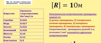
Table 1 shows the resistivity values of some substances.
| Substance | $\rho$, $\frac{Ohm \cdot mm^2}{m}$ | Substance | $\rho$, $\frac{Ohm \cdot mm^2}{m}$ |
| Silver | $0.016$ | Manganin (alloy) | $0.43$ |
| Copper | $0.017$ | Constantan (alloy) | $0.50$ |
| Gold | $0.024$ | Mercury | $0.96$ |
| Aluminum | $0.028$ | Nichrome (alloy) | $1.1$ |
| Tungsten | $0.055$ | Fechral (alloy) | $1.3$ |
| Iron | $0.10$ | Graphite | $13$ |
| Lead | $0.21$ | Porcelain | $10^{19}$ |
| Nickelin (alloy) | $0.40$ | Ebonite | $10^{20}$ |
Table 1. Resistivity of some substances (at $t = 20 \space \degree C$)
Please note that these values are valid at a temperature of $20 \space \degree C$.
The resistivity of a substance depends on temperature.
Experiments have shown that at a certain temperature for each substance, a dielectric can become a conductor (semiconductor). It has also been experimentally proven that with increasing temperature the resistivity of metals increases.
What does it depend on?
The indicator depends on temperature and differs in different materials.
Temperature dependence
It differs in each name of the material, in particular:
- In conductor elements, as the temperature increases, it increases.
- At the same time, in semiconductors, as well as dielectrics, it decreases under the same conditions.
The value that takes into account the change parameter is usually called the temperature coefficient.
Resistivity of different materials
Let's consider the indicator of single crystals at a temperature parameter of 20 degrees.
| Tin | 9,9–14,3 |
| Bismuth | 109–138 |
| Cadmium | 6,8–8,3 |
| Zinc | 5,91–6,13 |
| Tellurium | 2.90x10⁹–5.9x10⁹ |
Table for metals
The table shows indicators for metals, as well as individual alloys. The difference in parameters is directly related to chemical purity, casting methods, and the variability of the alloy itself.
| Silver | 0,015–0,0162 |
| Copper | 0,01707–0,018 |
| Gold | 0,023 |
| Aluminum | 0,0262–0,0295 |
| Iridium | 0,0474 |
| Sodium | 0,0485 |
| Molybdenum | 0,054 |
| Tungsten | 0,053–0,055 |
| Zinc | 0,059 |
| Indium | 0,0837 |
| Nickel | 0,087 |
| Iron | 0,099 |
| Platinum | 0,107 |
| Tin | 0,12 |
| Lead | 0,217–0,227 |
| Titanium | 0,5562–0,7837 |
| Mercury | 0,958 |
| Bismuth | 1,2 |
Use of substances for the manufacture of conductors and isolates
Which substances have the highest resistivity values? Of course, with dielectrics. For example, ebonite and porcelain practically do not conduct electricity. That's why they are used as insulators .
Pure metals have the lowest resistivity. Silver and copper are the best conductors of electricity.
What substances are conductors used in practice made from? Most often, copper, aluminum and iron wires are used for wiring electrical circuits.
In Table 1, you may also have noticed the resistivity values for alloys of several substances. They have quite large values. For what? They are usually used for the manufacture of devices that need to have a high resistance for normal functioning, but still pass current.
The concept of resistance is clear
This is a quantity that determines the ability of a semiconductor element to pass electric current through itself. A general concept can be given based on the basic structure of metals. A metal consists of a crystal lattice, between the elements of which electrons travel. The external field will cause them to create an electric current when moving. The lattice allows them to move through a given volume, and the electrons will rub against its nodes and will not be able to squeeze through. This phenomenon is called resistance, namely: a force that will interfere with movement.
It can be even easier to imagine using a strainer on the sink. The water will move slower than it would without it.
@yaklass.ru
How to calculate?
The value of the coefficient can be determined from the last equation. Thus we obtain the resistivity formula: $ρ=R*{S \over L}$.
Each substance is characterized by its own individual meaning. Therefore, for example, two wires of exactly the same length and thickness (cross-section), but made of different metals, will have significantly different resistances. This is due to the fact that the atoms of different substances differ from each other in mass, which depends on the number of protons, neutrons and electrons.
