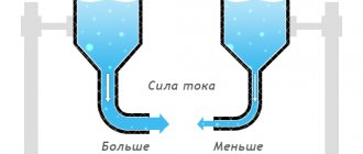
What is the difference between resistance and conductivity?
Resistance, by definition, is a measure of the "friction" a component presents for current to flow through it. Resistance is symbolized by the capital letter "R" and is measured in units of "ohms". However, we can also think of this electrical property in its inverse: how easy it is for current to flow through a component, rather than how difficult it is.
If resistance is the term we use to express a measure of how difficult it is for current to flow, then a good term to express how easily current flows would be conductance. Mathematically, conductivity is the reciprocal of resistance:
\[conductivity = \frac{1}{resistance}\]
The greater the resistance, the less the conductivity; and vice versa.
This should be intuitive because resistance and conductance are opposite ways of referring to the same important electrical property.
If we compare the resistances of two components and find that component "A" has half the resistance of component "B", then alternatively we could express this relationship by saying that component "A" is twice as conductive as component " B". If component "A" has a resistance equal to only one-third that of component "B", then we can say that it is three times more conductive than component "B", and so on.
Electrical resistance of a conductor. Electrical conductivity
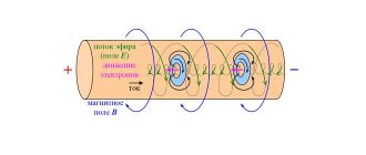
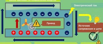
Every body has a certain resistance to the passage of electric current. For example, when electrons move along a conductor, they will collide with atoms and molecules of a substance, giving them part of their energy. The more such collisions, the greater the amount of resistance provided by the body to the movement of the electron, and, consequently, the less the current in the conductor.
Definition: The property of a conductor to prevent the passage of electric current through it is called electrical resistance, or resistance.
Resistance is denoted by the Latin letters R or r .
The unit of resistance is the ohm (abbreviated as Ohm or Ω).
The resistance of a conductor is equal to one ohm if, with a voltage at its ends of one volt, a current of one ampere is established in it.
In practice, resistance is often measured in kiloohms (abbreviated kOhm or kΩ) and megohms (abbreviated MOhm or MΩ).
1 kOhm = 1000 Ohm;
1 MΩ = 1000 kΩ = 1,000,000 Ω.
To characterize the electrical properties of conductors, the reciprocal of resistance, called conductance, is often used.
Definition: Electrical conductivity (or conductivity) is the ability of a substance to pass electric current through itself.
The greater the resistance of a conductor, the less its conductivity, and vice versa. Conductivity is denoted by the Latin letter G. The unit of conductivity is the conductivity of a conductor with a resistance of 1 ohm. This unit is called siemens (sim).
The concepts of resistance and conductivity are very important in electrical engineering. If a substance has little resistance (high conductivity), then it is called a conductor of electric current , or a conductor . Conductors include most metals (silver, copper, aluminum, iron, nickel, lead, mercury), as well as metal alloys, sea water, solutions of salts and acids, etc. Silver and copper conduct electric current especially well (they have the best conductivity ). Conductors are used to connect individual elements of electrical circuits.
But there are substances that conduct electric current very poorly, that is, they have very high resistance. Such substances are called non-conductors of electric current , or insulators . Insulators include porcelain, glass, wool, resin, rubber, ebonite, mica, wax, paraffin, etc. Insulators are widely used in electrical engineering. Without them, not a single electrical circuit can be implemented.
It should be remembered that usually the insulator resistance is several million times greater than the conductor resistance.
In addition to conductors and insulators, in nature there are so-called semiconductors of electric current. Their conductivity is greater than that of insulators, but less than that of conductors. Semiconductors include: germanium, silicon, selenium, tellurium, many oxides, carbides, sulfides, a huge number of alloys and chemical compounds (gallium arsenide, etc.), etc.
A characteristic feature of semiconductors is that their resistance varies over a wide range under the influence of light, electric and magnetic fields, radioactive radiation and foreign impurities.
Some semiconductors are used to make thermistors (resistors whose value changes sharply with temperature) and photoresistors (their resistance value depends on the light).
Semiconductors are used to make diodes, transistors, thyristors and integrated circuits.
The possibility of using semiconductors to amplify and generate oscillations was discovered in 1922 by an employee of the Nizhny Novgorod Radio Laboratory named after V.I. Lenin, radio amateur O.V. Losev, who named the device he invented cristadine.
DID YOU LIKE THE ARTICLE? SHARE WITH YOUR FRIENDS ON SOCIAL NETWORKS!
Related materials:
- Current flow
- Electric current in metal conductors
- Electromotive force (EMF) of the energy source
- Direction and magnitude of electric current. Amount of electricity
- Electric current in electrolytes
- Bias current in dielectric
- Electric current in semiconductors
- Electric current in gases
Add a comment
Conductivity unit
As a continuation of this idea, the symbol and unit for measuring conductivity were invented. The symbol was a capital letter "G" and the unit of measurement was mho, which means "ohm" spelled backwards (you thought electronics people didn't have a sense of humor?).
Despite their relevance, the mho units were replaced in subsequent years by the Siemens unit (abbreviated "Sm", or, in English literature, "S"). This decision to change the names of units of measurement is reminiscent of changing the temperature unit from degrees centigrade to degrees Celsius, or changing the unit measure frequency cps (cycles per second) in hertz. If you are looking for some kind of renaming pattern here, then Siemens, Celsius and Hertz are the names of famous scientists whose names, unfortunately, tell us less about the nature of the units than their original designations.
Returning to our parallel circuit example, we should be able to see that multiple paths (branches) for current reduce the overall resistance of the entire circuit, since current can flow more easily through an entire circuit of several branches than through any one of them individually. In terms of resistance, additional branches result in a smaller overall value (current encounters less resistance). However, from a conductance perspective, additional branches result in a larger overall value (current flows with greater conductivity).
Basic electrical quantities
- home
- Measuring instruments
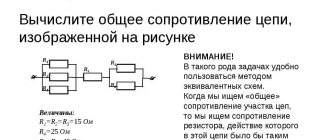
Let's consider the basic electrical quantities that we study first at school, then in secondary and higher educational institutions. For convenience, we will summarize all the data in a small table. Definitions of individual quantities will be given after the table in case of any misunderstandings.
| Magnitude | SI unit | Name of electrical quantity |
| q | Kl - pendant | charge |
| R | Om - om | resistance |
| U | V – volt | voltage |
| I | A – ampere | Current strength (electric current) |
| C | F – farad | Capacity |
| L | Mr. Henry | Inductance |
| sigma | CM - Siemens | Electrical conductivity |
| e0 | 8.85418781762039*10-12 f/m | Electrical constant |
| φ | V – volt | Electric field point potential |
| P | W – watt | Active power |
| Q | VAR – volt-ampere-reactive | Reactive power |
| S | Va – volt-ampere | Full power |
| f | Hz - hertz | Frequency |
There are decimal prefixes that are used in the name of the quantity and serve to simplify the description. The most common of them are: mega, miles, kilo, nano, pico. The table shows other prefixes, except those mentioned.
| Decimal multiplier | Pronunciation | Designation (Russian/international) |
| 10-30 | cuecto | q |
| 10-27 | ronto | r |
| 10-24 | iocto | and/y |
| 10-21 | zepto | s/z |
| 10-18 | atto | a |
| 10-15 | femto | f/f |
| 10-12 | pico | p/p |
| 10-9 | nano | n/n |
| 10-6 | micro | μ/μ |
| 10-3 | Milli | m/m |
| 10-2 | centi | c |
| 10-1 | deci | d/d |
| 101 | soundboard | yes/da |
| 102 | hecto | g/h |
| 103 | kilo | k/k |
| 106 | mega | M |
| 109 | giga | G/G |
| 1012 | tera | T |
| 1015 | peta | P/P |
| 1018 | exa | E/E |
| 1021 | zeta | Z/Z |
| 1024 | yotta | Y/Y |
| 1027 | Ronna | R |
| 1030 | quecca | Q |
The strength of an electric current of 1A is a value equal to the ratio of a charge of 1 C passing through a surface (conductor) in 1 s of time to the time of passage of the charge through the surface. For current to flow, the circuit must be closed.
Current strength is measured in amperes. 1A=1Kl/1c
In practice there are
1kA = 1000A
1mA = 0.001A
1uA = 0.000001A
Electric voltage is the potential difference between two points in an electric field. The magnitude of electrical potential is measured in volts, therefore voltage is measured in volts (V).
1 Volt is the voltage that is necessary to release 1 Watt of energy in a conductor when a current of 1 Ampere flows through it.
The unit of electric current voltage is the following ratio: 1V=1W/1A.
In practice, the following variants of units of measurement of electric potential, or rather potential difference, are encountered:
- 1kV = 1000V
- 1mV = 0.001V
Electrical resistance is the characteristic of a conductor that prevents electric current from flowing through it. It is defined as the ratio of the voltage at the ends of the conductor to the current in it. Measured in ohms (ohms). Within certain limits the value is constant.
1 Ohm is the resistance of a conductor when a direct current of 1A flows through it and a voltage of 1V arises at the ends.
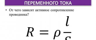
From the school physics course we all remember the formula for a homogeneous conductor of constant cross-section:
R=ρlS – the resistance of such a conductor depends on the cross-section S and length l
where ρ is the resistivity of the conductor material, tabular value.
Between the three quantities described above, Ohm's law exists for a DC circuit.
The current in the circuit is directly proportional to the voltage in the circuit and inversely proportional to the resistance of the circuit - Ohm's law.
I=U/R
Electrical capacitance is the ability of a conductor to accumulate electrical charge.
Capacitance is measured in farads (1F).
1F = 1Kl/1V
1F is the capacitance of a capacitor between the plates of which a voltage of 1V occurs when charged at 1C.
In practice there are
1pF = 0.000000000001F
1nF = 0.000000001F
Inductance is a quantity that characterizes the ability of a circuit through which electric current flows to create and accumulate a magnetic field.
Inductance is measured in henries.
1Gn = (V*s)/A
1H is a value equal to the self-inductive emf that occurs when the current in the circuit changes by 1A within 1 second.
In practice there are
1mH = 0.001H
Electrical conductivity is a value indicating the ability of a body to conduct electric current. Reciprocal of resistance.
Electrical conductivity is measured in siemens.
1cm = Ohm-1
How to choose a shunt for an ammeter
How to connect a pointer ammeter
Total parallel circuit conductance
The total conductance of a parallel circuit is greater than that of any of the individual branches because parallel resistors "conduct" better together than individually:
Figure 2 – Parallel circuit admittance
To be more precise, the total conductance in a parallel circuit is equal to the sum of the individual conductances:
\[G_{general} = G_1 + G_2 + G_3 + G_4\]
If we know that conductivity is nothing more than the mathematical reciprocal (1/x) of resistance, we can convert each term in the above formula into resistance by substituting the reciprocal of each corresponding conductivity:
\[\frac{1}{R_{total}} = \frac{1}{R_{1}} + \frac{1}{R_{2}} + \frac{1}{R_{3}} + \frac{1}{R_{4}}\]
Solving the above equation for impedance (instead of the reciprocal of total resistance), we get the following formula:
\[R_{total} = \frac{1}{\frac{1}{R_{1}} + \frac{1}{R_{2}} + \frac{1}{R_{3}} + \ frac{1}{R_{4}}}\]
So, we have finally arrived at our mysterious resistance formula! Conductivity (G) is rarely used as a practical parameter, so the above formula is often used when analyzing parallel circuits.
Complex numbers. Basic laws of electrical circuits in complex form
Definition 1
A complex number is a number of the form a + сi, where a and c are real numbers, and i is an imaginary unit, that is, a number for which the equality i(2) = -1 holds.
The set of complex numbers can be denoted by C. Real numbers are considered as a special case of complex numbers and have the following form a + 0i. The main property of a complex number is that the basic theorem of algebra is satisfied in it, that is, a polynomial of the nth degree (n ⩾ 1) has n roots. It has also been proven that the system of complex numbers is logically consistent.
Note 1
The Fundamental Theorem of Algebra is the statement that the field of complex numbers is algebraically closed, that is, any non-constant polynomial with complex coefficients has at least one root in the field of complex numbers. This statement is true for polynomials with real coefficients, because every real number is complex with zero imaginary part.
Are you an expert in this subject area? We invite you to become the author of the Directory Working Conditions
The need to use complex numbers arose as a result of solving cubic equations, since in the Cardano formula a negative number was obtained under the square root. Scientists such as Euler, Gauss and Descartes made great contributions to the study of complex numbers. The properties of complex numbers make it possible to use them in solving various problems in the field of elasticity theory, mathematics, signal processing, vibration theory, electromagnetism, control theory, etc.
The laws of electrical circuits of alternating current in complex form have the same form as circuits of direct electric current, with the replacement of constant quantities as follows:
Figure 1. Formula. Author24 - online exchange of student work
Finished works on a similar topic
Course work Complex resistance and conductivity 460 ₽ Abstract Complex resistance and conductivity 270 ₽ Test work Complex resistance and conductivity 230 ₽
Receive completed work or specialist advice on your educational project Find out the cost
The basic laws of electrical circuits include:
- Ohm's law.
- Kirchhoff's first law.
- Kirchhoff's second law.
In complex form, Ohm's law will have the following form:
Figure 2. Formula. Author24 - online exchange of student work
Kirchhoff's first law applied to a knot in complex form is as follows:
Figure 3. Formula. Author24 - online exchange of student work
Kirchhoff's second law, as applied to the circuit contour, can be written in complex form as follows:
Figure 4. Formula. Author24 - online exchange of student work
The advantage of expressing the laws of electrical circuits in a complex form is that they take into account the relationship between the effective values of voltage and current, as well as the phase shift between them.
Complex resistance. Physical meaning
Definition 2
Complex electrical resistance (electrical impedance) is the complex resistance between two nodes of an electrical circuit or two-terminal network for a harmonic oscillation.
Complex resistance is the ratio of the complex amplitude of the voltage of the harmonic signal, which is applied to the two-terminal network, to the complex amplitude of the electric current that flows through the two-terminal network in steady state (that is, at the end of transient processes in the circuit). For passive linear circuits with constant parameters, in steady state the complex electrical resistance does not depend on time in any way. In the case when the time in the mathematical expression for complex resistance is not reduced, the concept of complex resistance for a two-terminal network is not applicable. The formula for electrical impedance itself is as follows:
Figure 5. Formula. Author24 - online exchange of student work
where: j is the imaginary unit; w—circular frequency; U(w). I(w) - amplitudes of voltage and electric current at frequency w; Фu(w), Фi(w) — phases of voltage and current of the harmonic signal at frequency w; U(jw), I(jw) are the complex amplitudes of voltage and electric current of a harmonic signal at frequency w.
If we consider the complex electrical resistance in algebraic form, then its real part corresponds to the active resistance, and the imaginary part corresponds to the reactive one. That is, a two-terminal network with impedance z(jw) is a series-connected resistor with resistance R (z(jw)) and a reactive element with complex resistance J(z(jw)).
When complex resistance is considered in trigonometric form, its magnitude corresponds to the ratio of the voltage and current amplitudes (phase shift is not taken into account), and the argument corresponds to the phase shift between electric current and voltage.
For a resistor, the complex electrical resistance is always equal to its own and does not depend on frequency in any way, that is:
$zR=R$
The voltage and electric current in a capacitor are related by the relationship:
$i(t) = C*(dU/dt)$
Therefore, at voltage
Figure 6. Formula. Author24 - online exchange of student work
The electric current that flows through the capacitor can be calculated as follows:
Figure 7. Formula. Author24 - online exchange of student work
From here, the complex resistance of the capacitor is calculated using the formula:
$zC(jw) = 1/(jwC) = -(j/(wC).$
Similarly to calculating the complex resistance for a capacitor, the calculation formula for an inductor is obtained:
$zL(jw)=jwL$