Electrical distribution networks with a voltage of 6-10 kV are one of the oldest technological solutions in Russia. Many lines have a venerable age and a multi-stage history of modernization. Despite the planned reduction in the share of such overhead lines in the country’s overall power grid, the length of medium-voltage overhead lines amounts to thousands of kilometers. There are common cases when the length of overhead lines exceeds standard values. All this does not contribute to increasing the reliability of the electrical grid infrastructure.
According to available data in Russia, the duration of power outages ranges from 70 to 100 hours per year [1]. This figure is almost 2 times higher than in Western countries [1]. According to experts, for every 100 km of overhead power lines, up to 26 outages are recorded annually [1]. This article discusses the main causes of emergency outages of 6-10 kV high-voltage power lines.
Fig.1. High-voltage power lines (VL) 10 kV
Automation systems and devices in 6-10 kV networks
Overhead lines are made for the most part using steel-aluminum and aluminum wires, supports made of reinforced concrete or wood. Today, the following automation systems and devices are used in 6-10 kV networks:
- restart devices;
- devices for switching on backup power;
- sectioning devices;
- control and signaling devices.
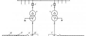
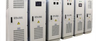
Power lines are connected in an extensive network through an automatic transfer point. When the network load is from 10 to 100 kVA, pole-type substations are used, which are installed on a support. For loads from 160 kVA, closed or kiosk substations are most often used. In 6-10 kV electrical networks, the installation of external vacuum switches and fuses-disconnectors is provided.
Rice. 2. Closed transformer substation
3Uo voltage alarm
Mandatory and very important function in networks with isolated and compensated neutral.
3Uo is a very reliable and stable sign of the presence of an SGC, in contrast to the 3Io current.
The capacitive current is shifted relative to the voltage by up to 90 degrees. inclusive, so when it is maximum, the voltage has a minimum value. All this contributes to the appearance of unstable short circuits, which current selective protection against short circuits cannot always detect.
Voltage 3Uо during OZZ always appears instantly, and when the fault current disappears, it decreases slowly. This property of 3Uo makes it easy to record this voltage and build reliable signaling based on this effect.
The disadvantage of the 3Uo OZZ alarm is that the voltage rises throughout the entire section, and it is impossible to identify a damaged feeder.
Malfunctions in control systems of automated systems
Automated telecontrol and telesignaling tools provide the ability to monitor the correct operation of installed restart devices, backup power switching devices, and automated sectioning devices. However, when introducing such functionality into the existing medium voltage overhead line infrastructure, certain problems arise. Let's highlight the main ones:
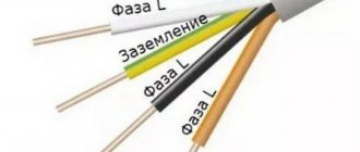
- distortion of the received data due to the impact of adverse meteorological conditions;
- the need to use special encoding and decoding equipment;
- the need to invest significant funds in the process of introducing technology and operating such systems.
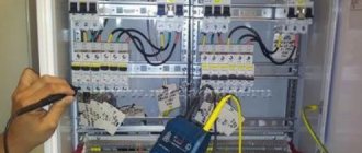
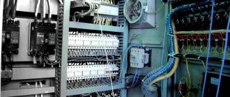
Rice. 3. Modernization of medium voltage overhead lines
Reasons for shutting down power lines
According to information from power grid companies, overhead power lines with a total length of more than 1.1 million km are currently in operation in Russia. In the European part of the country, overhead lines are mostly made of AC wires with a cross-section of 35 -70 square meters. mm. Up to 60% of the lines were put into operation before 1975. Most of these power grids have exhausted their standard operational life.
Rice. 3. Recommended distances between overhead line supports
New overhead power lines are being put into operation in insufficient quantities. At the same time, with an increase in the number of consumers, it is used, as a necessary measure, to exceed the distance between support pillars. The excess reaches two or more times [1]. These factors lead to an increase in the number of outages in power grids and reduce the quality and reliability of lines. An analysis of recorded emergency shutdowns shows that for the most part, stable shutdowns prevail. This parameter continues to show steady growth, especially in rural areas.
The increasing number of trips has a significant impact on the performance of connected automatic reclosers (ARs). It is worth noting that autorecloser devices are not installed on all circuit breakers. This is explained by the fact that drives of outdated models are often used.
The main causes of accidents leading to disconnection of overhead lines with voltage of 6-10 kV:
- wire break;
- mechanical damage to supports and insulators;
- physical wear and tear of materials and equipment;
- ground fault;
- tripping of fuses in transformer substations;
- exposure to natural precipitation and factors;
- relay protection tripping
- other extraneous influences.
According to statistics, the most common causes of power outages are the activation of relay protection and automation systems, the negative impact of natural phenomena (sharp gusts of wind, the formation of ice and snow cover on wires.
Despite the fact that power grid companies are in some places carrying out reconstruction work and modernizing existing networks, the number of outages is significantly higher than in Western countries. In addition, electricity losses in 6-10 kV distribution networks have increased. To correct the situation, it is necessary to increase the volume of capital expenditures for the reconstruction of existing infrastructure.
Power supply for industrial enterprises - Schemes of distribution networks 6-10 kV
Page 7 of 14
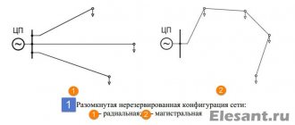
At small and medium-sized enterprises, as well as at the second and subsequent stages of power supply to large enterprises, electricity distribution is carried out mainly through 6-10 kV cable lines. Overhead lines are rarely built in lightly trafficked areas of the territory, for example, in peripheral areas. There are two main energy distribution schemes - radial and main, but often mixed schemes are used at different stages of power supply. One or another scheme is used depending on the number and relative location of workshop substations or other electrical receivers in relation to the point that supplies them. This also takes into account the cost of different options, cable consumption, methods of network implementation, etc. Both of these schemes, if properly implemented, can be used to ensure reliable power supply to electrical receivers of any category. Radial power distribution schemes are used mainly in cases where the loads are located in different directions from the power center. They can be two-stage or single-stage. Single-stage schemes are used mainly in small enterprises where the distributed power and territory are small. At large and medium-sized enterprises, both single-stage and two-stage schemes are used. Single-stage radial circuits at such enterprises are used to power large concentrated loads (pumping, compressor, converter units, electric furnaces, etc.) directly from the power center (GPP, CHP, etc.), and to power small workshop substations and power receivers For high voltage, two-stage schemes are used, since it is inappropriate to load the main energy centers of the enterprise (GPP, CHPP) with a large number of small outgoing lines. In two-stage radial circuits, intermediate distribution networks are used, from which the second-stage distribution networks are powered. All switching equipment is installed on the distribution switchgear, and at the workshop substations fed from them, predominantly blind connection of transformers is provided (without switches, disconnectors and other switching devices). Sometimes a load switch or disconnector is used. Each distribution point usually supplies four to five workshop substations. To effectively use the RP, its power is selected in such a way that the lines supplying it, selected by short-circuit current, are fully loaded (taking into account the post-emergency mode). The number of lines departing from the distribution point, as a rule, should be at least eight to ten. Radial circuits with more than two stages are cumbersome and impractical, since this complicates switching and protection; Sometimes they are used when developing an enterprise and when it is necessary to add new substations or to power individual peripheral substations. With radial schemes, sectioning of all links of the power supply system from gas production points and thermal power plants to low-voltage busbars of workshop substations and workshop power distribution points is widely used. Sectional devices are equipped with simple ATS circuits. This significantly improves power reliability. Large substations and distribution centers are fed by at least two radial lines, which usually operate separately, each in its own section; When one of them stops working, the other automatically takes over the entire load of power receivers of the 1st and 2nd categories. If each line is not designed for the full capacity of the entire substation, then measures are taken to unload the substation from non-essential consumers for the period of post-emergency operation. In Fig. Figure 6 shows a two-stage radial distribution diagram of electricity in one of the areas of a large enterprise, one of the PGVs of which is connected to a deep 110 kV input. Each of the distribution points is powered by two 10 kV lines (first stage network). At the second stage, electricity is distributed between two-transformer or one-transformer workshop transformer substations. Redundancy of power receivers of the 1st category at single-transformer substations is carried out by 400 V jumpers between the nearest transformer substations. Deep sectioning and automatic transfer switches are provided at all stages from PGV to low-voltage busbars of workshop substations. A 10/6 kV substation is connected to RP1 to power a group of 6 kV electric motors. On very large distribution centers, powerful bushings are used, consisting of many cables, and busbars of several sections. One of the schemes of such RP is shown in Fig. 7. Busbars are divided into three sections according to the number of inputs. ATS of sectional switches is provided. The most critical electrical receivers are connected to the middle section, the power of which must be provided under any conditions. Shop substations are two-transformer, with ATS capability at a voltage of 400 V. Sometimes distribution points are powered from two different sources. In this case, the distribution of loads between the latter is carried out depending on their power, distance, efficiency and other conditions. Low-power or remote sources, as a rule, serve only for redundancy.
Rice. 6. An example of a two-stage radial circuit.
Rice. 7. Scheme of radial power supply of workshop substations from a large distribution center with three bus sections.
Radial power supply circuits for distribution centers and substations with redundancy using a common backup main line connecting one by one to all substations, or using backup high-voltage jumpers are rarely used, for example, in cases where it is necessary to introduce emergency power from another power source in the event of a complete outage main source. From the point of view of cable consumption and costs, such a scheme is beneficial when substations are located close to each other and when they are located at a significant distance from the supply center. To power power receivers of the 1st and 2nd categories, two-transformer workshop substations are used; Each transformer is powered by a separate line according to a block diagram. Lines and transformers are designed to power all loads in normal mode and critical loads (1st and 2nd categories) in emergency conditions when one line or transformer fails. If there is no exact data on the categories of power receivers, each line and each transformer are selected for 60-70% of the total load of the entire substation. Then, in the event of an accident, taking into account the permissible overload of the transformers, they will provide power to all critical electrical receivers. On the secondary voltage side with this scheme, if necessary, an ATS of a sectional machine is used. The circuit turns out to be clear and reliable, but the use of automatic machines increases the cost of a complete transformer substation (CTS). If in a given workshop power consumers of the 3rd category predominate, then single-transformer substations are used. In these cases, it is advisable to carry out mutual redundancy of small groups of critical loads connected to these substations using cable jumpers between adjacent substations (see Fig. 6). The capacity of these jumpers is usually no more than 15-20% of the transformer load. In the transformer-low-voltage line block diagram, such redundancy is very simple, cheap and reliable using bus normally open jumpers between the ends of the lines of adjacent transformers. With low voltage jumpers, simultaneously with the transformers, the high voltage lines feeding them are also backed up. Rice. 8. Radial power supply of separate single-transformer substations. In addition, the presence of backup jumpers makes it possible to completely shut down several workshop substations during periods of low loads, which makes it possible to reduce no-load losses of transformers, improve the operating mode of the installation and increase its power factor. Rice. 9. Diagram of radial power supply of a transformer substation with connection of two radial lines under a common switch. Separately located (remote) small single-transformer substations are powered by a single radial line without high voltage redundancy (Fig. 8, a), if there are no power receivers of the 1st category and quick repair of a damaged line, for example, overhead or cable, laid in a channel is possible . Power supply to separate substations for more critical purposes may be carried out via a two-cable line with disconnectors on each cable (Fig. 8, b). In normal mode, only one cable works, the second is disconnected from the receiving end, but is under voltage and is constantly ready to be turned on; it turns on only after disconnecting the damaged working cable from both sides. If the cables are designed to carry short-circuit current, then both of them can be under constant load; in the event of an accident, the entire line is first disconnected, and then the damaged cable is located and disconnected by disconnectors and the entire load is transferred to the working cable. With this option, energy losses are reduced. When constructing radial power distribution schemes, it is necessary to take into account the need for rational use of switchgears.
Rice. 10. Scheme of radial power distribution of 6-10 kV RP using group reactors. It is not advisable to connect low-power lines (for example, to 100-1000 kV-A transformers) to a separate switchgear chamber, especially if it is an expensive switchgear chamber or a reacted line. Such lines must be grouped and connected to one switch. In Fig. Figure 9 shows a power distribution diagram where two radial lines are connected to one common switch. The circuit is constructed in such a way that each workshop transformer substation is powered from two different radial lines connected to different sections of the distribution switchgear. On the low voltage side, an ATS device is provided for the sectional machine. Consequently, if one of the lines is damaged, the entire main load is automatically taken up by the other line, which is taken into account when choosing the cross-section of lines and transformers. It is necessary for electrical industry factories to produce complete chambers according to the diagram shown in Fig. 9. At reacted substations, up to four lines can be connected to one group reactor, each of which has its own switch that selectively disconnects the damaged line without disrupting the operation of the others. In Fig. Figure 10 shows a diagram of a powerful GPP with group response of 6-10 kV lines extending to the distribution point. Thanks to the presence of an ATS on the sectional switch RP, the power supply to consumers connected to the damaged line is automatically restored in any case. The 6-10 kV current conductors in this diagram are connected directly to the transformers through separate switches. Thanks to this, the input switches are unloaded, independent power is created for the busbars from other consumers connected to the busbars, and thereby the overall reliability of the power supply increases. In mainline schemes, electricity is supplied from the main energy unit or power center of the enterprise (CHP, GPP) directly to shop distribution and transformer substations. The number of power distribution and switching units is reduced. This is the main and very significant advantage of backbone energy distribution schemes.
It is advisable to use trunk circuits for distributed loads, with an ordered (close to linear) arrangement of substations on the territory of the plant. This allows for the most direct passage of lines from power sources to energy consumers without reverse energy flows and without long detours. Rice. 11. Trunk circuits with one-way power supply. a - single; b - double. Trunk circuits are more convenient and economical than radial ones when it is necessary to back up shop substations from another source in the event of the main supply point going out of service. Trunk lines make it possible to better load cables during normal operation, the cross-section of which was selected based on economic current density or short-circuit current. As is known, the cable cross-section is selected taking into account the passage of short-circuit current through it. It is always larger than the cross-section required for low-power radial lines when passing normal operating current. For trunk lines, to which several substations are connected, due to their more complete loading, the cable cross-section required in normal operation approaches the cross-section selected according to short circuit conditions or economic current density. Trunk circuits also make it possible to save the number of cameras in the switchgear, since several substations are connected to one trunk line. The latter is very important when using expensive complete withdrawable switchgear cabinets. The indicated advantages of main circuits are reflected mainly when comparing them with single-stage radial circuits or with radial circuits at the second stage of energy distribution for powering small transformers and other electrical receivers. The number of transformers connected to one main line depends on their power and the responsibility of the consumers supplied. The larger the transformers, the fewer of them can be connected to one main line. It must be taken into account that with a large number of transformers and their close connection to the main line (see Fig. 12), the maximum protection at the head section of the supply main becomes rougher and may turn out to be insensitive in the event of a short circuit in a given transformer. A way out of this situation may be to install fuses on the branch from the main to the transformer, as shown in Fig. 11. This makes it possible to selectively turn off the transformer if it is damaged. The number of transformers fed from one main line can be approximately taken to be within two or three for transformer power of 2500-1000 kVA and four to five for power of 630-250 kVA. Based on the degree of reliability of power supply, main circuits can be divided into two main groups.
Single lines with partial power redundancy via secondary voltage connections. The first group includes simple backbone circuits - single (Fig. 11, a) and ring ones. These schemes, as a rule, are inferior to radial schemes in terms of reliability of power supply and ease of operation. Therefore, they are rarely used, mainly to power low-power substations, whose consumers can be classified as category 3. Single lines without redundancy are used in cases where it is possible to allow a power interruption for the time necessary to find, disconnect and restore a damaged section of the line, which is convenient, for example, with air lines. With cable mains, their route must be accessible for repairing cables at any time of the year, which is possible, for example, when laying in channels, tunnels, etc. The reliability of a circuit with single mains can be increased if the single-transformer substations fed by them are located in such a way that It was possible to implement partial redundancy along low voltage connections between nearby substations. For this, the circuit shown in Fig. is used. 12, in which closely located single-transformer substations are powered by different single mains. This makes it possible for partial mutual redundancy of these substations via low-voltage connections in the same way as with radial energy distribution schemes. Such improved main circuits can also be used for power receivers of the 1st category, if the load of the latter is small - no more than 15-20% of the total load. Branches from overhead lines are made through a disconnector without the line entering the substation. Rice. 13. Schemes of double through lines with one-way power supply. a - in the presence of high-voltage busbars at substations; b - in the absence of high-voltage busbars at substations. If single mains are equipped with a common backup main, which alternately enters the end substations fed by working mains, then the reliability of the entire circuit increases and a power interruption is determined only by the time required to find and disconnect the damaged section of the main and connect the backup main. Such schemes can be allowed to supply consumers of the 2nd category. No more than four to five substations are usually connected to one main line, the power of each of which is in the range of 630–1000 kVA. The disadvantage of this scheme is that the backup cable line (cold backup) is not used under normal conditions, and therefore it is not widely used. Ring highways are rarely used in industrial enterprises. The second group of trunk circuits includes more complex circuits, with two or more parallel end-to-end highways. Schemes with double through lines are used at substations with two sections of busbars (Fig. 13, a) or at two-transformer substations without high-voltage busbars (Fig. 13.6). Such circuits, although more expensive, are very reliable and can be used to power electrical receivers of any category. Their reliability is determined by the fact that each section of substation buses or each transformer of a two-transformer substation is powered from different mains, each of which is designed to cover the main loads of all substations; transformers are also designed for mutual redundancy. Depending on the transmitted power, from two to four substations can be connected to each main line. Sections of RP buses or transformers of shop TPs operate separately in normal mode, and if there is a fault on one of the mains, they are switched to the main that remains in operation. If necessary, this can be done automatically using an automatic transfer switch on a sectional switch (Fig. 13, a) or on a sectional machine (Fig. 13.6). With such reliable schemes, it is possible not to install switching devices at the input and output of the main line, and with a system of two-transformer substations, it is even possible not to install automatic disconnecting devices (switches, fuses) at the input to the transformer, if the necessary power reserve of transformers for mutual redundancy is provided and if the protection is on the head section of the main line is sensitive to damage in the transformer. This simplifies the switching circuit and the design of substations, which is especially important for reducing the cost of complete factory-made substations.
In Fig. Figure 14 shows single and double mains with two-way power supply, otherwise called “counter” mains. They are used in cases where power is required from two independent sources, either to ensure reliability of power supply, or to meet special requirements. Often one of the sources is the main one, and power is normally supplied from it, and the second - low-power, remote or uneconomical - is emergency. In these cases, the switch at the end of the line (at the second IP) is normally open and turns on only when the line is disconnected from the main source. Switching on can be done either manually or automatically. If, under normal conditions, both sources can be rationally used, then to reduce electricity losses it is advisable to keep them constantly under load. In this case, the main line is divided approximately in the middle, at one of the intermediate substations. To save cells and devices at the supply center, two lines can be connected to one switch or to one reactor.
Rice. 14. Trunk circuits with two-way power supply. a - single; b - double in the absence of high-voltage busbars at workshop substations. In Fig. Figure 15 shows a diagram of the main power supply of the RP with the connection of two mains to one common reactor, and each main has a separate switch. The RP sections receive power from different mains, which in turn are connected to different sections of the IP (in this case, the GPP). If one of the lines is damaged, its switch is turned off, but at the same time the sections of all RP connected to it are automatically switched to the second line using the ATS sectional switch device. Thus, the circuit ensures uninterrupted power supply.
Rice. 15. Main circuit for power supply of a distribution switch with one reactor for two mains. If the enterprise has “special” groups of electrical receivers listed in § 1, their power supply is carried out in such a way that when any element of the system is taken out for long-term repairs or revision, the power supply of these electrical receivers is always maintained from two independent sources, i.e. in those cases , when for all other electrical receivers there is temporarily only one source left. The power supply scheme provides for the supply of power from an emergency source only to the mentioned electrical receivers of a special group, so as not to overestimate its power, which depends on the nature of the technology. To ensure constant readiness of the emergency source for immediate switching on, it is provided for its transfer to the “hot” standby mode immediately after one of the two main power sources is disconnected for any reason. This is done by turning on the emergency diesel station at idle speed, turning on the emergency jumper from another source, etc. In Fig. 16, a shows the power supply diagram for one of the areas of a large enterprise with two main independent sources in the form of two sections of the PGV.
For emergency power supply of special groups of electrical receivers available at RP2 and PII3, the diagram shows a dotted line that enters these RPs one by one and is powered by a third emergency source of low power; as the latter, any independent source listed in § 3 can be used. If there is an automatic transfer switch at the distribution point, emergency power can be automatically supplied to the distribution point to which special groups of electrical receivers are connected. At RP1 there are no “special” groups of electrical receivers and therefore the emergency main line is not provided for entry there. The scheme works as follows. If the voltage is lost on one of the sections RP2 or RPZ, then sectional switch 1 is automatically turned on and all power to these RPs is transferred to only one source via the remaining power line. Then a third source is immediately prepared to provide power to a “special” group of electrical receivers in case there is a complete loss of power to RP2 or RPZ from the PGV. In this case, switch 2 of the emergency line is automatically turned on. To avoid overloading the third source, the power supply of “special” groups is allocated or automatic shutdown of the remaining electrical receivers is provided before the third power source is introduced. In Fig. 16.6 shows the power supply diagram of a large enterprise, the power of which is supplied: from the power system through the URP and from its own thermal power plant. Cable jumpers between PGV1 and PGV2 and between RP1 and PGVZ provide power to special groups of electrical receivers in the event of any emergency, including even a complete shutdown of the URP or thermal power plant. In this case, no special emergency source was required. These examples show how it is possible, relatively inexpensively and simply, to provide completely reliable power to electrical receivers of a “special” group, the uninterrupted operation of which is necessary for an accident-free shutdown of production. At enterprises, especially large ones, they are usually not limited to any one of the schemes described above. To supply power to individual parts of such objects, it is sometimes advisable to use various schemes that provide the most economical and rational solution for the entire power supply system as a whole: For example, at the first stage of energy distribution for cable networks, radial schemes are usually used, and for busducts - main ones. Further distribution of energy over individual sections from the distribution center to workshop substations and high-voltage motors at such enterprises is carried out both according to radial and mainline schemes. However, one should not allow a large variety of schemes at one facility, as this is undesirable for reasons of unification of design solutions and ease of operation. In Fig. Figure 17 shows, as an example, part of a complete power supply circuit for a large industrial plant. The main power is supplied from G/7777 with three three-winding transformers with a capacity of 180 MV-A, 220/110/10 kV. In addition, there is a thermal power plant with two turbogenerators with a capacity of 60 MW, connected to GPP1 at a voltage of 10 kV. The distribution of electricity at the first stage is carried out in several ways. Very large electric furnaces and the remote substation G/7772 are powered by 110 kV deep input lines. Large LVs are powered by 10 kV conductors with reactors at thermal power plants. Other distribution centers are powered by reactive cable lines. At the second stage, the main distribution of electricity is carried out by radial cable lines. To power medium-power electric motors, an intermediate voltage of 6 kV was introduced. 10/6 kV substations, which serve to power 6 kV electric motors, are connected according to a block diagram: 10 kV line - 10/6 kV transformer. In Fig. Figure 18 shows a complete power supply diagram for a small enterprise, but with very critical loads of the 1st category. The distribution of electricity throughout the enterprise comes from two distribution points, each of which is connected to two independent sources A and B. A single busbar circuit at the distribution point is sectioned. The sectional switch is equipped with an ATS. Critical shop substations are two-transformer. The transformers are powered by different distribution centers located at the closest distance from each other; according to the block diagram, the line is a transformer without busbars and without switches on the 6-10 kV side. If the distribution points were significantly removed from each other, then it would be more expedient to supply power to the workshop substations from different sections of the same distribution point. The 0.4 kV buses of workshop substations are sectioned using an automatic transfer switch on a sectional machine. Less critical workshop substations - single-transformer ones - are also powered from different RPs, from a cable ring normally open in the middle (by a switch installed on TS 2).
Rice. 17. Power supply diagram for a large industrial plant.
The circuit is designed in such a way that during an emergency mode, power supply to loads of the 1st and 2nd categories is automatically provided in any area, taking into account the overload capacity of lines and transformers and with the disconnection of non-critical consumers during a prolonged post-emergency mode.
Rice. 18. Power supply diagram for a small enterprise with critical loads. In the scheme, all transformers and cables are constantly loaded and operate in an economical mode with minimal possible power losses and cable consumption.
- Back
- Forward
Ways to improve the efficiency of medium voltage overhead lines
In the medium term, overhead lines with low losses and high throughput along with a long line length will become effective. To improve the efficiency of existing and newly introduced overhead lines, network operators have a number of options:
- conducting regular technical audits and diagnostics of the technical condition of existing infrastructure;
- development of a balanced program for the development of electrical distribution networks for the coming years;
- modernization and replacement of infrastructure elements whose standard service life has been exceeded;
- use of protected wires in rural areas and forested areas;
- ensuring the adaptability of networks to increased electrical loads, the introduction of new technologies and automation of electrical networks.