1 . 1 . This standard specifies the methods used to distinguish terminals and the general rules for their uniform designation.
Note: The term “terminal designation” is used to designate conductive sections of the circuit and electrical elements intended for connection.
1 . 2. A unified designation method can be used when using computer technology and transmitting information by teletype.
1 . 3. The drawings in this standard are provided as examples to clarify the text.
The distinctive features of the method indicated and I are:
1) arrangement of clamps according to the chosen system;
2) conventional color according to the chosen system;
3) conventional graphic designation according to GOST 2.721;
4) alphanumeric designation according to section. 4.
Note: The indicated methods are equally valuable from the point of view of their use.
It is allowed to use graphic symbols in accordance with GOST 2.721 instead of alphanumeric symbols (see Tables 1 and 2).
2. 2. The choice of designation method depends on the type of device, the location of the terminals, and the complexity of the device or wiring.
2. 3. Alphanumeric symbols are used for complex devices and wiring and are convenient for transmission by teletype.
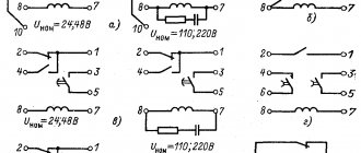
3. 1 . To designate the terminals of electrical elements, a conventional color and corresponding graphic or alphanumeric designation are used.
3. 2. When designating clamps with a conventional color, the relationship between the color and the equivalent graphic or alphanumeric designation must be shown in the accompanying documentation.
3. 3. If the design of a particular element or device does not allow a clamp to be designated, then the accompanying documentation must show the relationship between the location of the clamp, equivalent graphical or alphanumeric symbols, as well as the relative positions of the clamps.
4 . 1 . When constructing letters e-no-ts and frov notations, capital letters of the Latin alphabet and Arabic numerals are used.
It is not recommended to use the letters I and O.
It is allowed to omit one or more groups if this does not lead to an error during connections.
To separate groups consisting only of numbers or letters, use a dot. If there is no need to distinguish subsequent groups, the point can be omitted. For example, the full designation 1 U 11 can be written as follows: 1. 11, if there is no need to indicate group U; if there is no need to distinguish subsequent groups, the period can be omitted: 111.
4 . 3. It is allowed to use the signs “+” and “-” when transmitting by teletype.
Regulations
Taking into account the large number of electrical elements, a number of normative documents have been developed for their alphanumeric (hereinafter referred to as BO) and conventional graphic designations (UGO) to eliminate discrepancies. Below is a table showing the main standards.
Table 1. Standards for graphic designation of individual elements in installation and circuit diagrams.
| GOST number | Short description |
| 2.710 81 | This document contains GOST requirements for BO of various types of electrical elements, including electrical appliances. |
| 2.747 68 | Requirements for the dimensions of displaying elements in graphical form. |
| 21.614 88 | Accepted codes for electrical and wiring plans. |
| 2.755 87 | Display of switching devices and contact connections on diagrams |
| 2.756 76 | Standards for sensing parts of electromechanical equipment. |
| 2.709 89 | This standard regulates the standards in accordance with which contact connections and wires are indicated on diagrams. |
| 21.404 85 | Schematic symbols for equipment used in automation systems |
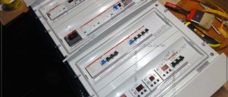
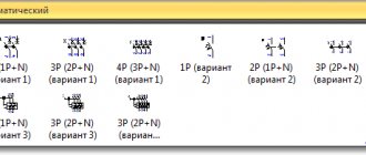
It should be taken into account that the element base changes over time, and accordingly changes are made to regulatory documents, although this process is more inert. Let's give a simple example: RCDs and automatic circuit breakers have been widely used in Russia for more than a decade, but there is still no single standard according to GOST 2.755-87 for these devices, unlike circuit breakers. It is quite possible that this issue will be resolved in the near future. To keep abreast of such innovations, professionals monitor changes in regulatory documents; amateurs do not have to do this; it is enough to know the decoding of the main symbols.
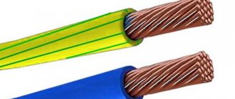
What color markings are there?
The color of the core of any wire is an indicator that determines its belonging to its functional group (neutral/zero, phase, grounding/ground). Because pinouting wires by color is a common color marking. Therefore, now you don’t need to rely on “maybe” when connecting. The latter, if carelessly, can lead, at best, to overheating of the cores or, even worse, to a short circuit. In this regard, having an idea of each shade of wire, be it phase or neutral, it is much easier to find the necessary contacts when connecting. And make the connection safely and securely. Pinout of wires by color allows you to increase the speed of installation. Because, in addition to color, there is also an alphanumeric code that also performs the task of identifying the core.
Safety precautions when working with electrical equipment: general information and basic measures
Color marking
Often the entire conductor has a uniform color, but it is also possible to mark only the ends of individual wires, which are switching points.
How to make heating in the garage yourself
Types of electrical circuits
In accordance with ESKD standards, diagrams mean graphic documents on which, using accepted notations, the main elements or components of a structure, as well as the connections connecting them, are displayed. According to the accepted classification, there are ten types of circuits, of which three are most often used in electrical engineering:
- Functional, it shows the node elements (depicted as rectangles), as well as the communication lines connecting them. A characteristic feature of this scheme is minimal detail. To describe the main functions of nodes, the rectangles displaying them are signed with standard letter designations. These can be various parts of the product that differ in functionality, for example, an automatic dimmer with a photo relay as a sensor or a regular TV. An example of such a scheme is presented below.
Example of a functional diagram of a television receiver - Fundamental. This type of graphic document displays in detail both the elements used in the design and their connections and contacts. The electrical parameters of some elements can be displayed directly in the document, or presented separately in the form of a table.
Example of a circuit diagram of a milling machine
If the diagram shows only the power part of the installation, then it is called single-line; if all elements are shown, then it is called complete.
Single Line Diagram Example
- Electrical wiring diagrams. These documents use positional designations of elements, that is, their location on the board, method and order of installation are indicated.
Installation diagram of a stationary flammable gas detector
Read also: Motor 3 phase 220 volts
If the drawing shows the wiring of the apartment, then the locations of lighting fixtures, sockets and other equipment are indicated on the plan. Sometimes you can hear such a document called a power supply diagram; this is incorrect, since the latter shows how consumers are connected to a substation or other power source.
Having dealt with the electrical circuits, we can move on to the designations of the elements indicated on them.
AC and DC circuits, tables: pinout of wires by colors, letters and numbers
In order to better understand the pinout of wires, we present to your attention tables that indicate the color and alphanumeric phasing, zero, and grounding in various electrical circuits.
AC electrical circuit DC electrical circuit
How to correctly report data for electricity: how to transmit, when and in what way
Graphic symbols
Each type of graphic document has its own designations, regulated by relevant regulatory documents. Let us give as an example the basic graphic symbols for different types of electrical circuits.
Examples of UGO in functional diagrams
Below is a picture depicting the main components of automation systems.
Examples of symbols for electrical appliances and automation equipment in accordance with GOST 21.404-85
Description of symbols:
- A – Basic (1) and acceptable (2) images of devices that are installed outside the electrical panel or junction box.
- B - The same as point A, except that the elements are located on the remote control or electrical panel.
- C – Display of actuators (AM).
- D – Influence of MI on the regulating body (hereinafter referred to as RO) when the power is turned off:
- RO opening occurs
- Closing RO
- The position of the RO remains unchanged.
- E – IM, on which a manual drive is additionally installed. This symbol may be used for any RO provisions specified in paragraph D.
- F- Accepted mappings of communication lines:
- General.
- There is no connection at the intersection.
- The presence of a connection at the intersection.
UGO in single-line and complete electrical circuits
There are several groups of symbols for these schemes; we present the most common of them. To obtain complete information, you must refer to the regulatory documents; the numbers of state standards will be given for each group.
Power supplies.
To designate them, the symbols shown in the figure below are used.
UGO power supplies on schematic diagrams (GOST 2.742-68 and GOST 2.750.68)
Description of symbols:
- A is a constant voltage source, its polarity is indicated by the symbols “+” and “-”.
- B – electricity icon indicating alternating voltage.
- C is a symbol of alternating and direct voltage, used in cases where the device can be powered from any of these sources.
- D – Display of battery or galvanic power supply.
- E- Symbol of a battery consisting of several batteries.
Communication lines
The basic elements of electrical connectors are presented below.
Designation of communication lines on circuit diagrams (GOST 2.721-74 and GOST 2.751.73)
Description of symbols:
- A – General display adopted for various types of electrical connections.
- B – Current-carrying or grounding bus.
- C – Designation of shielding, can be electrostatic (marked with the symbol “E”) or electromagnetic (“M”).
- D – Grounding symbol.
- E – Electrical connection with the device body.
- F - On complex diagrams, consisting of several components, a broken connection is thus indicated; in such cases, “X” is information about where the line will be continued (as a rule, the element number is indicated).
- G – Intersection with no connection.
- H – Joint at intersection.
- I – Branches.
Designations of electromechanical devices and contact connections
Examples of the designation of magnetic starters, relays, as well as contacts of communication devices can be seen below.
UGO adopted for electromechanical devices and contactors (GOSTs 2.756-76, 2.755-74, 2.755-87)
Description of symbols:
- A – symbol of the coil of an electromechanical device (relay, magnetic starter, etc.).
- B – UGO of the receiving part of the electrothermal protection.
- C – display of the coil of a device with mechanical interlock.
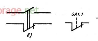
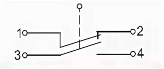
- D – contacts of switching devices:
- Closing.
- Disconnecting.
- Switching.
- E – Symbol for designating manual switches (buttons).
- F – Group switch (switch).
UGO of electric machines
Let us give several examples of displaying electrical machines (hereinafter referred to as EM) in accordance with the current standard.
Designation of electric motors and generators on circuit diagrams (GOST 2.722-68)
Description of symbols:
- A – three-phase EM:
- Asynchronous (squirrel-cage rotor).
- The same as point 1, only in a two-speed version.
- Asynchronous electric motors with phase-phase rotor design.
- Synchronous motors and generators.
- B – Collector, DC powered:
- EM with permanent magnet excitation.
- EM with excitation coil.
Designation of electric motors on diagrams
UGO transformers and chokes
Examples of graphic symbols for these devices can be found in the figure below.
Correct designations of transformers, inductors and chokes (GOST 2.723-78)
Description of symbols:
- A – This graphic symbol can indicate inductors or windings of transformers.
- B – Choke, which has a ferrimagnetic core (magnetic core).
- C – Display of a two-coil transformer.
- D – Device with three coils.
- E - Autotransformer symbol.
- F – Graphic display of CT (current transformer).
Designation of measuring instruments and radio components
A brief overview of the UGO of these electronic components is shown below. For those who want to become more familiar with this information, we recommend viewing GOSTs 2.729 68 and 2.730 73.
Examples of graphic symbols for electronic components and measuring instruments
Description of symbols:
- Electricity meter.
- Picture of an ammeter.
- Device for measuring network voltage.
- Thermal sensor.
- Fixed value resistor.
- Variable resistor.
- Capacitor (general designation).
- Electrolytic capacity.
- Diode designation.
- Light-emitting diode.
- Image of a diode optocoupler.
- UGO transistor (in this case npn).
- Fuse designation.
UGO lighting devices
Let's look at how electric lamps are displayed on a circuit diagram.
An example of how light bulbs are indicated on diagrams (GOST 2.732-68)
Description of symbols:
- A – General image of incandescent lamps (LN).
- B – LN as a signaling device.
- C – Typical designation of gas-discharge lamps.
- D – High-pressure gas-discharge light source (the figure shows an example of a design with two electrodes)
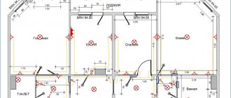
Designation of elements in the electrical wiring diagram
Concluding the topic of graphic symbols, we give examples of displaying sockets and switches.
An example of an image on the wiring diagrams of flush-mounted sockets
How sockets of other types are depicted is easy to find in the regulatory documents that are available on the Internet.
Designation of flush-mounted switches
Designation of sockets and switches
Color coding
3-phase and direct current
3-phase AC networks include high-voltage conductors and buses with the following colors:
- Yellow – for A-phase,
- Green – for B-phase,
- Red – for C-phase.
Color coding for 3-phase network
DC power networks are characterized by the presence of only two buses:
- minus-negative
- plus-positive
They are marked in blue and red colors sequentially. The middle M-wire is colored blue or light blue. Neutral and current-carrying wires are fundamentally absent in such electrical networks. In the case when a two-wire network is created from a branch from a 3-wire DC circuit, its conductors are marked in the same way as the color of the cores of the “mother” network.
Household electrical networks
Color coding for household networks
As it was before
In those days when the standard for colored cores had not yet been introduced, their insulation was black or white. Of course, the presence of only two colors seriously burdened the installation work. Especially in those places where it was only necessary to reconnect existing circuits. This is where the biggest difficulties arose. Finding where the phase and where the zero is was quite a problematic task.
How to fix bluetooth headphones for a phone, if one doesn’t work, the microphone or plug is broken, the contact has come loose and other cases
Modern pinout of wires by color
Now, according to GOST requirements, any conductor in electrical appliances and installations operating in networks up to 1 kV must have a strictly defined color. Modern pinout of wires by color has the following colors in the marking of various types of cores:
- neutral or zero (N) – the neutral working conductor is made in blue or light blue. On the distribution panel, the zero is attached to a special bus using a terminal or a bolt under a nut, welded to the body of the box (the panel of the old design),
- protective neutral conductor (PE), “ground”, grounding wire – the color of this conductor is always yellow-green, designed in the form of longitudinal or transverse stripes on the insulation of the conductive conductors,
- combined neutral wire (neutral + ground, PEN) – marked yellow-green with blue marks at the ends or vice versa,
- phase (L) – one of the colors shown in the figure. The most common phase conductors are those with red, white, black or brown insulation. The phase on the panel always comes to the “machine” or fuse.
The main meaning of the color marking of the working core of a single-phase electrical network is that the branches from the 3-phase circuit match in color the same shade of the original conductor core of the “mother” network.
These standards for marking electrical conductors are designed specifically in such a way as to prevent the slightest similarity between the colors of the insulation of current-carrying conductors and the colors of neutral conductors. Even if the cable is not marked, at its end, at the connection points, appropriate distinctive markings are made using multi-colored electrical tape, cambric or heat shrink.
How to properly design corners on a ceiling plinth
Phase coloring
When installing an electrical installation using rigid metal busbars, in this case the tires are painted with indelible paint in the following colors:
- yellow - phase A (L1);
- green - phase B (L2);
- red - phase C (L3);
- blue - zero bus;
- stripes of yellow and green colors - grounding bus.
Phase colors
The color of the phases must be maintained throughout the entire device, but not necessarily over the entire surface of the bus. It is allowed to mark the phase designation only at the connection points. On a painted surface, you can duplicate the color with the “ZhZK” symbols for paint of the corresponding colors.
Tires need not be painted only if they are inaccessible for inspection or work and there is tension on them.
The color of phase wires connected to rigid busbars may not coincide with them in color, since there is a difference in the accepted designation systems for flexible conductors and rigid stationary distribution busbars.
Neutral color
When the installation of the power plant appears before your eyes, the color of the neutral wire should not raise doubts or questions. It is specified by GOST standards, according to which the blue wire is zero, since the blue color and its shades (blue) are accepted to indicate neutral (working grounding).
Color marking of wires for Russia, Belarus, Ukraine
It is not allowed to paint neutral cores in other colors.
There is only one acceptable option in which the use of blue and cyan insulation indicates the negative pole or midpoint in DC circuits. This color cannot be used anywhere else.
Ground wire marking
Just like other wires in electrical installations, the ground wire has its own set color - yellow-green. Thanks to such a bright shade, it is clearly visible against the background of other veins. The following color variation for this wire is acceptable: with yellow insulation and a green stripe on it, or vice versa, green insulation with a yellow stripe. It is not allowed to use any other color of the ground wire, just as it is not allowed to use green-yellow conductors for installing circuits on which voltage is present or may be applied.
Repair of heated floors
All of the above labeling rules have been adopted in the countries of the post-Soviet space, as well as in the countries of the European Union. We did not consider other states. They have their own color pinout of wires, which is not often found here, but on imported equipment, we can see their markings.