- home
- Installation of GPON networks: what tools to use?
The most popular technology for subscriber access via optical fiber now is passive optical networks, abbreviated PON from the English words Passive Optical Networks. This technology is better known to a wide range of consumers in the GPON version, that is, Gigabit PON, a passive optical network operating at speeds of the order of gigabit/s. The fact is that the GPON connection service is provided by many Internet providers and this term has already become familiar in advertising.
The essence of PON is that a large group of consumers (for example, an entire apartment building or its entrance) is supplied with a signal via one optical fiber. In this case, the distribution of the signal among consumers and the summation of signals coming from consumers are carried out by passive optical splitters.
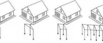
PON network architecture
Upstream and downstream transmission occurs in optical fiber at different wavelengths. There is also a wavelength used for cable television transmission. The information flow going to subscribers is broadcast, each subscriber selects from it the data fields intended specifically for him. In the direction from the subscriber, to combine information flows, the principle of time division access (TDMA) is used, when each subscriber is allocated its own time period in which it can transmit information. GPON and simply PON communication networks usually have a tree structure.
In order to understand what the tool should be that will be used by specialists installing GPON networks, let’s consider how to work with optical cables, including in relation to this data transmission technology.
Fiber Optic Cable Cutting Tool
At all stages of work with an optical cable: input control of the fiber optic cable, installation of optical couplings, cross-connects, and so on, an appropriate tool is required for cutting the fiber cable. A set of all necessary tools and materials for cable cutting - NIM-25 (installation tool set) (Fig. 1). The universal kit allows you to mount optical cables with armor made of steel wire, corrugated steel tape, glass rods, including aramid threads and glass fibers, as well as a lightweight universal indoor cable. To cut an optical cable built into a lightning cable (OCGT), it is recommended to complete the kit with a device for cutting a metal module with OM OM SSD.
Rice. 1. NIM-25 Set of tools for cable cutting
Rice. 2. Knife for metal module
Composition of the NIM-25 kit
The first group of tools is fairly standard (Fig. 3) from left to right, top to bottom: wire cutters (cable cutters) for cutting steel wire, including various cables and wires, side cutters, sprayer (spray gun), pliers.
Rice. 3. Tool included in NIM-25
The following group of tools (Fig. 4) from left to right, top to bottom: stripper for removing the buffer, T-type stripper for removing 0.4-1.3 mm (26-16 AWG) sheaths, scissors for cutting reinforcing cable threads, mounting knife.
Rice. 4. Tool included in NIM-25
The third group (Fig. 5), from left to right, from top to bottom: metal tweezers, stripper-clothespin for removing external modules, tape measure, magnifying glass.
Rice. 5. Tool included in NIM-25
A very important and necessary tool when cutting various designs of optical cables is a stripper for removing the outer sheath of the cable (Fig. 6). The depth of the position of its cutting knife is adjusted with a flat screwdriver, depending on the thickness of the shell that we want to cut - first a transverse and then a longitudinal cut is made and then the shell is removed. It is important to remember that during the process of cutting the shell with a stripper, the module with the optical fiber inside must remain undamaged (no cuts, creases, etc.).
Rice. 6. Tool included NIM-25 (stripper for optical fiber)
Auxiliary tools and materials: headlamp, adhesive tape, lint-free wipes, electrical tape, 250 ml alcohol dispenser with pump, D-Gel liquid for removing hydrophobic filler (Fig. 7), set of screwdrivers, hacksaw, container for useful small items ( Fig. 8).
To clean the optical cable from hydrophobic filler, a special liquid D-Gel is used (Fig. 7, right). For ease of work, a rag is moistened with D-Gel and then the mounted cable is wiped with the wet part. After wet wiping, wiping with a dry cloth is necessary. As a result, we get pure OK.
Lint-free wipes are used to wipe optical fibers; in addition, they remove static electricity from the optical fiber.
Rice. 7. Material in the composition of NIM-25
Rice. 8. Tool included in NIM-25
Optical cable cutting
Working with each type of OC has its own characteristics and nuances that must be taken into account. Below are video instructions for cutting various FOC structures.
DPT cable cutting
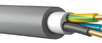
Standard suspended self-supporting optical cable (Fig. 9). Modular twist construction, reinforced with aramid yarns and an intermediate shell.
Rice. 9. Optical cable DPT
Cutting process OK
Using a tape measure, the required cutting length of the fiber-optic cable is measured and the corresponding mark is placed. The outer shell of polymer material is cut (first across the mark, then along OK) with the blade of a Kabifix FK28 stripper (Fig. 6) or another similar tool and then removed. Important note: the stripper adjusted to the thickness of the sheath must first be checked at the OK end (10–15 cm), that is, make sure that the knife does not damage other structural elements of the optical cable.
The reinforcing element in the form of an aramid thread is cut using scissors for cutting reinforcing threads (Fig. 4, bottom left). The intermediate shell is similarly cut and removed using a Kabifix FK28 stripper (Fig. 6). Before starting work, the stripper must be adjusted to the new shell thickness. After removing the intermediate shell, several layers of winding threads are removed from the twisted optical modules (they need to be pryed and cut).
Next, the bundle of optical modules is untwisted, the central power element (CSE) and cords (if any) are cut off to the required length, the entire remaining structure is wiped with a rag moistened with D-Gel liquid (Fig. 7, right).
In the process of working with an optical cable, removing each layer (external, internal, intermediate, strengthening and power elements, etc.), the central power element (CSE) should not break.
The optical module is removed from the bundle of optical fibers using a clothespin stripper (Fig. 5, top right). Using a stripper, you need to make a transverse cut in the module in the right place, then carefully break it and pull it out by its tip. After removing the module, the bundle of optical fibers is wiped with a dry lint-free cloth to remove excess hydrophobe, then the cloth is moistened with isopropyl alcohol (Fig. 7, left) and the bundle of optical fibers is wiped again, but with alcohol.
Video instructions for cutting DPT optical cable:
DPS cable cutting
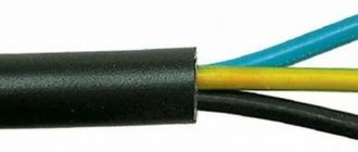
Standard optical cable for laying in the ground (Fig. 10). Construction with modular stranding, steel wire armor and intermediate sheath.
Rice. 10. Optical cable DPS
Cutting process OK
Using a tape measure, the required cutting length OK is measured and the corresponding mark is placed. The outer shell of polymer material is cut (first across the mark, then along OK) with the blade of a Kabifix FK28 stripper (Fig. 6) or another similar tool and then removed. Important note: the stripper adjusted to the thickness of the sheath must first be checked at the OK end (10–15 cm), that is, make sure that the knife does not damage other structural elements of the optical cable.
The winding thread is removed from the bundle of wire armor. Using cable cutters (Fig. 4, top right), the wire armor is cut to the required distance. The inner shell is wiped with a rag moistened with D-Gel liquid. The intermediate shell is similarly cut and removed using a Kabifix FK28 stripper (Fig. 6). Before starting work, the stripper must be adjusted to the new shell thickness. After removing the intermediate shell, several layers of winding threads are removed from the twisted optical modules (they need to be pryed and cut).
Next, the bundle of optical modules is untwisted, the central power element (CSE) and cords (if any) are cut off to the required length, the entire remaining OK structure is wiped with a rag moistened with D-Gel liquid (Fig. 7, right).
In the process of working with an optical cable, removing each layer (external, internal, intermediate, strengthening and power elements, etc.), the central power element (CSE) should not break.
The optical module is removed from the bundle of optical fibers using a clothespin stripper (Fig. 5, top right). Using a stripper, you need to make a transverse cut in the module in the right place, then carefully break it and pull it out by its tip. After removing the module, the bundle of optical fibers is wiped with a dry lint-free cloth to remove excess hydrophobe, then the cloth is moistened with isopropyl alcohol (Fig. 7, left) and the bundle of optical fibers is wiped again, but with alcohol.
Video instructions for cutting DPS optical cable:
Cable termination DOL
Standard optical cable for installation in cable ducts (Fig. 11). Design with modular twist and steel tape.
Rice. 11. Optical cable DOL
Cutting process OK
Using a tape measure, the required cutting length OK is measured and the corresponding mark is placed. The outer shell of polymer material is cut across the mark using a Kabifix FK28 stripper blade (Fig. 6) or another similar tool. Important note: the stripper adjusted to the thickness of the sheath must first be checked at the OK end (10–15 cm), that is, make sure that the knife does not damage other structural elements of the optical cable.
Then, using a Kabifix FK28 stripper or a mounting knife, transverse cuts are made (from the end of the cable) and the sheath of the optical cable, together with the steel tape, is pulled towards the OK end. To facilitate the process of tightening the shell with the armor, it is recommended to make transverse cuts every 20–30 cm. After removing the shell with the tape, several layers of winding threads are removed from the twist of the optical modules (they need to be pryed and cut) and the water blocking tape.
Next, the bundle of optical modules is untwisted, the central power element (CSE) and cords (if any) are cut off to the required length, the entire remaining OK structure is wiped with a rag moistened with D-Gel liquid (Fig. 7, right). If there are cordels in the design, they are bitten off.
In the process of working with an optical cable, removing each layer (external, internal, intermediate, strengthening and power elements, etc.), the central power element (CSE) should not break.
The optical module is removed from the bundle of optical fibers using a clothespin stripper (Fig. 5, top right). Using a stripper, you need to make a transverse cut in the module in the right place, then carefully break it and pull it out by its tip. After removing the module, the bundle of optical fibers is wiped with a dry lint-free cloth to remove excess hydrophobe, then the cloth is moistened with isopropyl alcohol (Fig. 7, left) and the bundle of optical fibers is wiped again, but with alcohol.
Video instructions for cutting optical cable DOL:
See the Knowledge Base for video instructions on cutting optical cables with other designs.
Optical fiber connection
Welding connection
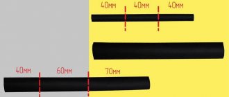
When welding, the sequence of actions differs in that before removing the protective layer, a heat-shrinkable sleeve is put on one of the ends of the cable for rigid fixation and protection from moisture. Next, the fiber is cleaved using a special tool so that the end plane is strictly perpendicular to the fiber axis (deviation of no more than 1 degree is allowed). After chopping, the optical fiber on both sides of the cable is placed into the welding machine and fixed in the manner described in the instructions for the device. The lid of the welding machine is closed, then welding and testing of the strength of the connection occur automatically. After this, the protective sleeve is shifted so that its middle coincides with the welding site. Next, the connection point is placed in a special oven, where, due to heat shrinkage, the sleeve tightly covers the cable, ensuring tightness.
Connection using detachable mechanical connections
Installation of an optical fiber in an SC connector is also preceded by cleaning the fiber end from protective coatings and degreasing. The fiber is secured in the connector using epoxy resin. Epoxy resin is injected into the connector channel, and a hardener is injected onto the end of the fiber. The optical fiber is inserted into the connector channel so that the end of the fiber protrudes from the connector at a distance sufficient for subsequent processing. Previously, this was followed by heating in an oven, after which the epoxy resin polymerized. Nowadays, fast-hardening epoxy resins are used that do not require baking. But they require certain skill from the staff to ensure that the fiber is correctly inserted into the connector the first time, otherwise the connector will be damaged.
After the epoxy resin has hardened, the protruding end of the optical fiber is cleaved to the required length, and then grinding follows - giving the end surface an optimal shape, ensuring a tight fit between the ends of the two fibers in combination with minimal losses and distortion of the transmitted signal. Experts believe that the best option is to give the end surface an inclination angle of 8 degrees relative to the plane perpendicular to the axis of the optical fiber.
Connection using splices
When connecting an optical fiber with splices, the above-mentioned preparatory work, common to all types of connections, is performed, as well as chopping the optical fiber at a right angle. Modern splices are usually supplied already filled with gel. The optical fibers to be connected are carefully inserted into the splice from both sides using special guides. They are securely fixed in the splice. Repeated reconnections using the same splice are possible up to 10 times. To protect against external influences, the splice is placed in a special cassette, sometimes called a “plate”.