Insulation resistance values for electrical equipment and systems
(PEARL/NETA MTS-1997 Standard Table 10.1)
| Rated maximum equipment voltage | Megger class | Minimum insulation resistance value |
| 250 V | 500 V | 25 MOhm |
| 600 V | 1000 V | 100 MOhm |
| 5 kV | 2500 V | 1000 MOhm |
| 8 kV | 2500 V | 2000 MOhm |
| 15 kV | 2500 V | 5000 MOhm |
| 25 kV | 5000 V | 20000 MOhm |
| 35 kV | 15000 V | 100000 MOhm |
| 46 kV | 15000 V | 100000 MOhm |
| 69 kV | 15000 V | 100000 MOhm |
1 MΩ Rule for Equipment Insulation Resistance Value
Depending on the rated voltage of the equipment:
> 1 kV = 1 MΩ per 1 kV
According to IE Rules - 1956
When 1000 V is present between each live conductor and earth for one minute, the insulation resistance of high voltage installations shall be not less than 1 MΩ or as specified by the Bureau of Indian Standards. Medium Voltage and Low Voltage Installations - If 500 V is present between each live conductor and ground for one minute, the insulation resistance of Medium Voltage and Low Voltage Installations shall be not less than 1 MΩ or as specified by the Bureau of Indian Standards. According to CBIP specifications, acceptable values are 2 MΩ per kV.
Medium Voltage and Low Voltage Installations - If 500 V is present between each live conductor and ground for one minute, the insulation resistance of Medium Voltage and Low Voltage Installations shall be not less than 1 MΩ or as specified by the Bureau of Indian Standards.
According to CBIP specifications, acceptable values are 2 MΩ per kV
Measurement conditions
4.1 The measurement is carried out indoors at a temperature of 25±10°C and a relative air humidity of no more than 80%, unless other conditions are provided for in the standards or technical specifications for cables, wires, cords and equipment.
4.2 The value of the electrical insulation resistance of the connecting wires of the measuring circuit must exceed at least 20 times the minimum permissible value of the electrical insulation resistance of the product under test.
4.3. It is recommended to measure the insulation characteristics of electrical equipment using the same type of circuits and at the same temperature. Comparison of insulation characteristics should be made at the same insulation temperature or similar values (temperature difference no more than 5°C). If this is not possible, then a temperature recalculation must be made.
2. Insulation resistance value for transformer
Insulation resistance testing is necessary to determine the insulation resistance of individual windings to ground or between individual windings. In this type of testing, insulation resistance is usually either measured directly in MΩ or calculated from the applied voltage and the magnitude of the leakage current.
When measuring insulation resistance, it is recommended to always ground the frame (and core). Short-circuit each transformer winding to the bushing terminals. After this, measure the resistance between each winding and all other grounded windings.
Insulation resistance testing: between high voltage side and ground, and between high voltage side and low voltage side. HV1 (2, 3) - Low voltage 1 (2, 3); LV1 (2, 3) - High voltage 1 (2, 3))
When measuring insulation resistance, never leave the transformer windings ungrounded. To measure the resistance of a grounded winding, it is necessary to remove solid grounding from it. If it is not possible to remove the ground, as is the case with some windings with solidly grounded neutrals, the insulation resistance of such a winding will not be measurable. Consider them part of the grounded section of the circuit.
Testing must be done between windings and between winding and ground (E). On three-phase transformers, it is necessary to test the winding (L1, L2, L3) minus the ground for transformers with a delta connection or the winding (L1, L2, L3) with ground (E) and neutral (N) for transformers with a star connection.
Insulation resistance value for transformer
| Transformer | Formula |
| Single phase transformer | Insulation resistance value (MΩ) = CXE / (√kVA) |
| Three-phase transformer (star) | Insulation resistance value (MΩ) = CXE (P – n) / (√kVA) |
| Three-phase transformer (delta) | Insulation resistance value (MΩ) = CXE (P – P) / (√kVA) |
Where C = 1.5 for oil-filled transformers with an oil tank, 30 for oil-filled transformers without an oil tank or for dry transformers.
Temperature correction factor (relative to 20°C)
| Temperature correction factor | |
| °C | Correction factor |
| 0 | 0,25 |
| 5 | 0,36 |
| 10 | 0,50 |
| 15 | 0,720 |
| 20 | 1,00 |
| 30 | 1,98 |
| 40 | 3,95 |
| 50 | 7,85 |
Example for a three-phase transformer 1600 kVA, 20 kV / 400 V:
- insulation resistance value on high voltage side = (1.5 x 20000) / √1600 = 16000 / 40 = 750 MOhm at 20°C;
- insulation resistance value on low voltage side = (1.5 x 400) / √1600 = 320 / 40 = 15 MOhm at 20°C;
- insulation resistance value at 30°C = 15 x 1.98 = 29.7 MOhm.
Transformer winding insulation resistance
| Transformer winding voltage | Megger class | Minimum insulation resistance value for liquid transformer | Minimum insulation resistance value for a dry transformer |
| 0 – 600 V | 1 kV | 100 MOhm | 500 MOhm |
| 600 V – 5 kV | 2.5 kV | 1000 MOhm | 5000 MOhm |
| 5 kV – 15 kV | 5 kV | 1000 MOhm | 5000 MOhm |
| 15 kV – 69 kV | 5 kV | 10000 MOhm | 50000 MOhm |
Transformer insulation resistance value
| Voltage | Test voltage (DC), low voltage side | Test voltage (DC), high voltage side | Minimum insulation resistance value |
| 415 V | 500 V | 2.5 kV | 100 MOhm |
| Up to 6.6 kV | 500 V | 2.5 kV | 200 MOhm |
| 6.6 kV – 11 kV | 500 V | 2.5 kV | 400 MOhm |
| 11 kV – 33 kV | 1000 V | 5 kV | 500 MOhm |
| 33 kV – 66 kV | 1000 V | 5 kV | 600 MOhm |
| 66 kV – 132 kV | 1000 V | 5 kV | 600 MOhm |
| 132 kV – 220 kV | 1000 V | 5 kV | 650 MOhm |
Measuring the insulation resistance of a transformer:
- turn off the transformer and disconnect jumpers and lightning rods;
- discharge the interturn capacitance;
- completely clean all bushings;
- short-circuit the windings;
- Protect the terminals to prevent surface leakage across the terminal insulators;
- record the ambient temperature;
- connect test leads (avoid additional connections);
- Apply test voltage and record readings. The insulation resistance value 60 seconds after applying the test voltage is taken as the insulation resistance of the transformer at the testing temperature;
- The neutral terminal of the transformer must be disconnected from ground during testing;
- Also, during testing, all connections to the ground of the lightning rod on the low voltage side must be disconnected;
- due to the inductive characteristics of the transformer, insulation resistance readings must be taken only after the test current has stabilized;
- Do not take resistance readings while the transformer is under vacuum.
Transformer connections when testing insulation resistance (at least 200 MOhm)
Transformer with two windings 1. (High voltage winding + low voltage winding) - ground 2. High voltage winding - (low voltage winding + ground) 3. Low voltage winding - (high voltage winding + ground)
Three Winding Transformer 1. High Voltage Winding - (Low Voltage Winding + Tap Winding + Ground) 2. Low Voltage Winding - (High Voltage Winding + Tap Winding + Ground) 3. (High Voltage Winding + Low Voltage Winding + Tap Winding) - Ground 4. Tap Winding – (high voltage winding + low voltage winding + ground)
Autotransformer (two windings) 1. (High voltage winding + low voltage winding) - ground
Autotransformer (three windings) 1. (High voltage winding + low voltage winding) – (tap winding + ground) 2. (High voltage winding + low voltage winding + tap winding) – ground 3. Tap winding – (high voltage winding + low voltage winding + ground)
For any insulation, the measured insulation resistance should not be less than:
- high-voltage winding – ground 200 MOhm;
- low-voltage winding – ground 100 MOhm;
- high-voltage winding – low-voltage winding 200 MOhm.
Factors affecting the transformer insulation resistance value
The insulation resistance value of transformers is affected by the following:
- condition of the surface of the terminal bushing;
- oil quality;
- winding insulation quality;
- oil temperature;
- duration of use and test voltage value.
Safety requirements
ATTENTION! Do not start measurements without making sure that there is no voltage on the object being measured.
5.1. Before starting tests, it is necessary to make sure that there are no people working on that part of the electrical installation to which the test device is connected, to prohibit persons located near it from touching live parts and, if necessary, to set up security.
5.2. Measuring the insulation resistance with a megohmmeter should be carried out on disconnected live parts from which the charge has been removed by first grounding them. Grounding from live parts should be removed only after connecting the megohmmeter.
5.3. When measuring the insulation resistance of live parts with a megohmmeter, the connecting wires should be connected to them using insulating holders (rods).
5.4. When working with a megohmmeter, touching the live parts to which it is connected is not allowed. After completion of work, the residual charge should be removed from live parts by briefly grounding them.
Insulation resistance value for electric motor
An insulation tester is used to measure the grounded motor winding resistance (E).
- for rated voltages below 1 kV, measurement is carried out with a 500 V DC megger;
- for rated voltages above 1 kV, measurement is carried out with a 1000 V DC megger;
- According to IEEE 43 Article 9.3, the following formula should be applied: minimum insulation resistance value (for rotating machine) = (Rated Voltage (V) / 1000) +1.
Insulation resistance value for electric motor
In accordance with IEEE 43 1974, 2000
| Insulation resistance value in MOhm | |
| Insulation resistance (minimum) = kV + 1 | For most windings made before approximately 1070, all field windings and other windings not described below. |
| Insulation resistance (minimum) = 100 MΩ | For most DC rotors and AC windings manufactured after approximately 1070 (pattern coils). |
| Insulation resistance (minimum) = 5 MΩ | For most machines with non-patterned stator coils and patterned coils rated below 1 kV. |
Example 1: For a three-phase electric motor 11 kV
- insulation resistance value = 11 + 1 = 12 MΩ, but according to IEEE43 should be 100 MΩ.
Example 2: For a 415V three-phase motor
- insulation resistance value = 0.415 + 1 = 1.41 MΩ, but according to IEEE43 should be 5 MΩ;
- as per IS 732 minimum insulation resistance value for electric motor = (20 x Voltage (p-p)) / (1000 + 2 x kW).
Motor insulation resistance value according to NETA ATS 2007 Section 7.15.1
| Motor nameplate (B) | Test voltage | Minimum insulation resistance value |
| 250 V | 500 V DC | 25 MOhm |
| 600 V | 1000 V DC | 100 MOhm |
| 1000 V | 1000 V DC | 100 MOhm |
| 2500 V | 1000 V DC | 500 MOhm |
| 5000 V | 2500 V DC | 1000 MOhm |
| 8000 V | 2500 V DC | 2000 MOhm |
| 15000 V | 2500 V DC | 5000 MOhm |
| 25000 V | 5000 V DC | 20000 MOhm |
| 34500 V | 15000 V DC | 100000 MOhm |
Submersible motor insulation resistance value
| Submersible motor insulation resistance value | |
| Electric motor outside the well (without cable) | Insulation resistance value |
| New electric motor | 20 MOhm |
| Used motor that can be reinstalled | 10 MOhm |
| Electric motor installed in a well (with cable) | |
| New electric motor | 2 MOhm |
| Used motor that can be reinstalled | 0.5 MOhm |
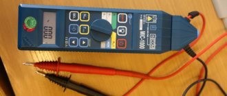
Types of testers
When operating electrical devices, digital megohmmeters of the model: F4101/4102 from 100.0 to 1000.0 V are widely used. Installers still work with tester brands M4100/1, 4100/5 and MS-05 m from 100.0 to 2500.0 V. The choice of megger size is based on rated resistance of the device under test: power cables and transformers, machines and insulators. To determine the state of insulation in electrical installations up to 1000.0 V, it is allowed to use megohmmeters from 100.0-1000.0 V, and in installations over 1000.0 V - 1000.0-2500.0 V.
Devices are also classified by the voltage generated and resistance limits in megohms:
- 500.0 V - 500.0;
- 1000.0 V - 1000.0;
- 2500.0 V - 2500.0.
Additional Information . The devices also differ in accuracy classes. The popular M4100 model has an error of no more than 1%, and the F4101 brand has an error of up to 2.5%. The selection of electrical installation testing devices is carried out taking into account acceptable performance indicators.
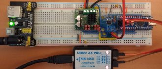
Electronic meter
Electronic meter
A digital or electronic tester is a modern type of equipment, equipped with a powerful generator with field-effect transistors. Measurements are made by comparing the voltage drop in a reference circuit with a fixed resistance. The results are shown on the panel. The test results saving function accumulates data for subsequent analysis. This model differs from analog devices in its compact size and light weight. Advantages of a digital tester:
- High level of accuracy, allows you to determine resistance over large sections of the circuit;
- convenient, easy-to-read digital panel;
- technological accessibility for measurement by one user;
- works great even in very busy spaces;
- convenient and safe to use.
You might be interested in this: Do-it-yourself diagram and description of the capacitor welding process
Disadvantages of the electronic type megger:
- Requires external power source;
- high prices for products.
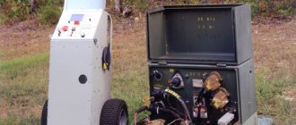
Electromechanical meter
Electromechanical device
These models have an analog display on the front panel of the tester and a hand crank used to rotate and generate voltage that passes through the electrical system.
Advantages of a manual megger:
- Remains important in today's high-tech world, remaining the oldest method for determining resistance values.
- No external source is required for operation.
- Low prices on the market.
Disadvantages of a manual megger:
- At least 2 people are required for operation, one to rotate the handle, the other to connect the megger to the electrical system being tested.
- Low measurement accuracy.
- Requires a large free space for placement.
- Provides an analog measurement result.
- High requirements for safety during use.
Circuit design features:
- Deflector and Control Coil - Connected in parallel with the generator, mounted at right angles to each other and maintained in polarity so as to produce torque in the opposite direction.
- Permanent magnets create a magnetic field to deflect the pointer using a North-South magnetic pole.
- Pointer - one end connected to the coil, the other deviates on a scale from infinity to “0”.
- A scale is provided at the top of the megger from the zero to infinity range and allows the user to read the value.
- Connecting a direct current (DC) source or battery.
- The test mode is generated by a generator for a manually controlled megger. A battery or electronic charger is provided for the digital megger for the same purpose.
Note! The current coil resistance helps protect the tester from any damage during testing due to the low external electrical resistance.
Insulation Resistance Value for Electrical Cables and Wiring
Insulation testing requires disconnecting cables from the panel or equipment and from the power source. Wiring and cables should be tested relative to each other (phase to phase) with the ground cable (E). The IPCEA (Insulated Power Cable Engineers Association) offers a formula for determining the minimum insulation resistance values.
R = K x Log 10 (D/d)
R = Insulation resistance value in megohms for 305 meters of cable K = Insulating material constant. (Electrical insulating lacquer cloth = 2460, thermoplastic polyethylene = 50000, composite polyethylene = 30000) D = Outside diameter of conductor insulation for solid wire or cable (D = d + 2c + 2b diameter of solid cable) d = Diameter of conductor c = Thickness of conductor insulation b = Insulating sheath thickness
High voltage testing of new XLPE cable (according to ETSA standard)
| Application | Test voltage | Minimum insulation resistance value |
| New Cables – Jacket | 1 kV DC | 100 MOhm |
| New cables - Insulation | 10 kV DC | 1000 MOhm |
| After recovery – Shell | 1 kV DC | 10 MOhm |
| After recovery - Isolation | 5 kV DC | 1000 MOhm |
11 kV and 33 kV cables between core and earth (according to ETSA standard
| Application | Test voltage | Minimum insulation resistance value |
| New 11 kV cables – Sheath | 5 kV DC | 1000 MOhm |
| 11 kV after restoration – Shell | 5 kV DC | 100 MOhm |
| 33 kV without connected TF | 5 kV DC | 1000 MOhm |
| 33 kV with connected TF | 5 kV DC | 15 MOhm |
11 kV and 33 kV cables between cores and ground
Measuring the insulation resistance value (between conductors (cross insulation))
- The first conductor to be measured for cross-insulation must be connected to the Line terminal of the megger. The other conductors are connected together (using alligator clips) and connected to the Earth terminal of the megger. At the other end, the conductors are not connected;
- then turn the knob or press the megger button. The meter display will show the insulation resistance between conductor 1 and the remaining conductors. Insulation resistance readings should be recorded;
- then connect another conductor to the Line terminal of the megger, and connect the other conductors to the ground terminal of the megger. Take a measurement.
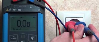
Measuring insulation resistance value (insulation between conductor and ground)
- connect the conductor under test to the Line terminal of the megger;
- connect the Earth terminal of the megohmmeter to ground.;
- turn the knob or press the megohmmeter button. The meter display will show the insulation resistance of the conductors. After maintaining the test voltage for a minute until a stable reading is obtained, record the insulation resistance value.
Measured values:
- If, during periodic testing, the insulation resistance of an underground cable at the corresponding temperature is from 5 MΩ to 1 MΩ per kilometer, this cable must be included in the replacement program;
- if the measured insulation resistance of an underground cable at the corresponding temperature is from 1000 kOhm to 100 kOhm per kilometer, this cable should be replaced urgently, within a year;
- If the measured cable insulation resistance is less than 100 kOhm per kilometer, this cable should be replaced immediately as an emergency cable.
Taking measurements
7.1. After making sure that there is no voltage on the object, connect the object to the “rx” sockets. If shielding is necessary, to reduce the influence of leakage currents, connect the object’s screen to socket “E”. To reduce the time it takes to establish readings before measuring resistance on scale II for 3-5 seconds. Rotate the generator handle with the “rx” terminals short-circuited.
7.2. To carry out measurements, rotate the generator handle at a speed of 120-144 rpm.
7.3. The reading of the electrical insulation resistance values during measurement is carried out after 1 minute from the moment the measuring voltage is applied to the sample, but not more than 5 minutes, unless other requirements are provided for in the standards or technical conditions for specific cable products or other equipment being measured. Before re-measurement, all metal elements of the cable product must be grounded for at least 2 minutes.
7.4. When measuring the insulation parameters of electrical equipment, random and systematic errors must be taken into account due to the errors of measuring instruments and apparatus, additional capacitances and inductive couplings between the elements of the measuring circuit, the effect of temperature, the influence of external electromagnetic and electrostatic fields on the measuring device, method errors, etc.
7.5. The electrical insulation resistance of multi-core cables, wires and cords must be measured:
- for products without a metal sheath, screen and armor - between each current-carrying conductor and the remaining conductors connected to each other or between each conductive conductor; residential and other conductors connected to each other and grounding.
- for products with a metal shell, screen and armor - between each current-carrying conductor and the remaining conductors connected to each other and to the metal shell or screen, or armor.
Insulation resistance value for transmission line/distribution line
| Equipment | Megger class | Minimum insulation resistance value |
| Substation equipment | 5 kV | 5000 MOhm |
| EHV lines | 5 kV | 10 MOhm |
| HT lines | 1 kV | 5 MOhm |
| LT lines/service lines | 0.5 kV | 5 MOhm |
Test standards for switchgear switchgear (KRUN) in operation.
The scope and standards of testing switchgear switchgear (CIRC) elements in operation (oil circuit breakers, instrument transformers, load switches, valve arresters, fuses, disconnectors, cables, etc.) are determined by the relevant sections of the rules. Additionally, tests must be carried out to the extent and within the time limits specified below. Preventative tests of switchgear (CIRC) are carried out during major repairs (K) and during the overhaul period (M). K - carried out within the time frame established by the PPR system, but at least once every 6 years. M - within the time limits established by the PPR system. The scope of preventive tests provided for by the PEEP includes the following work. 1. Measurement of insulation resistance: a) primary circuits; b) secondary circuits. 2. Tests with increased voltage of industrial frequency: a) cell insulation; b) isolation of secondary circuits. 3. DC resistance measurement. 4. Measuring the pressure of the lamellas of the disconnecting contacts of the primary circuit. 5. Checking withdrawable parts and interlocks.
Insulation resistance value for substation equipment
Typical resistance values for substation equipment are:
Typical insulation resistance value for substation equipment
| Equipment | Megger class | Minimum insulation resistance value | |
| Circuit breaker | (Phase – Earth) | 5 kV, 10 kV | 1000 MOhm |
| (Phase - Phase) | 5 kV, 10 kV | 1000 MOhm | |
| Control circuit | 0.5 kV | 50 MOhm | |
| CT/PT | (Primary – Earth) | 5 kV, 10 kV | 1000 MOhm |
| (Secondary – Phase) | 5 kV, 10 kV | 50 MOhm | |
| Control circuit | 0.5 kV | 50 MOhm | |
| Insulator | (Phase – Earth) | 5 kV, 10 kV | 1000 MOhm |
| (Phase - Phase) | 5 kV, 10 kV | 1000 MOhm | |
| Control circuit | 0.5 kV | 50 MOhm | |
| L.A. | (Phase – Earth) | 5 kV, 10 kV | 1000 MOhm |
| Electric motor | (Phase – Earth) | 0.5 kV | 50 MOhm |
| Switchgear LT | (Phase – Earth) | 0.5 kV | 100 MOhm |
| Transformer LT | (Phase – Earth) | 0.5 kV | 100 MOhm |
Insulation resistance value of substation equipment in accordance with DEP standard:
| Equipment | Measurement | Insulation resistance value at the time of commissioning (MOhm) | Insulation resistance value at the time of service (MOhm) |
| Switchgear | High voltage bus | 200 MOhm | 100 MOhm |
| Low voltage bus | 20 MOhm | 10 MOhm | |
| Low voltage wiring | 5 MOhm | 0.5 MOhm | |
| Cable (minimum 100 meters) | High voltage and low voltage | (10 x kV)/km | (kV)/km |
| Electric motor and generator | Phase – Earth | 10 (kV + 1) | 2 (kV + 1) |
| Transformer immersed in oil | High voltage and low voltage | 75 MOhm | 30 MOhm |
| Transformer, dry type | High voltage | 100 MOhm | 25 MOhm |
| Low voltage | 10 MOhm | 2 MOhm | |
| Stationary equipment/tools | Phase – Earth | 5 kOhm per volt | 1 kOhm per volt |
| Removable equipment | Phase – Earth | 5 MOhm | 1 MOhm |
| Distribution equipment | Phase – Earth | 5 MOhm | 1 MOhm |
| Circuit breaker | Power circuit | 2 MΩ per kV | — |
| Control circuit | 5 MOhm | — | |
| Relay | DC Circuit - Ground | 40 MOhm | — |
| Circuit LT - Ground | 50 MOhm | — | |
| LT – DC circuit | 40 MOhm | — | |
| LT–LT | 70 MOhm | — |
Testing of complete switchgear devices for indoor and outdoor installation (switchgear and switchgear)
The scope of inspection and testing of switchgear switchgear (KRUN) is determined by the volumes and standards of testing of individual elements included in their composition and must comply with the requirements of clause 1.8.22. PUE and Chapter 12 “Test Standards for Electrical Equipment” during acceptance tests and clause 20 of Appendix 1 of PEEP during operation. Test standards for switchgear components (KRUN): oil circuit breakers, instrument transformers, load switches, valve arresters, fuses, disconnectors, power transformers and transformer oil are determined by the relevant sections of the rules.
Insulation Resistance Value for Household/Industrial Wiring
Low resistance between phase and neutral conductors or between live conductors and earth will result in leakage current. This leads to deterioration of insulation, as well as energy losses, which will result in increased operating costs for the installed system. At normal supply voltages, the phase-to-phase-neutral-to-earth resistance should never be less than 0.5 MΩ.
In addition to the leakage current due to the active resistance of the insulation, there is also a leakage current due to its reactance, since it acts as the dielectric of a capacitor. This current does not dissipate any energy and is not harmful, but we need to measure insulation resistance, so DC voltage is used to prevent reactance measurement from being included in the test.
Single phase wiring
Insulation resistance testing between phase-neutral and ground should be performed on the entire installation with the power switch turned off, with the line and neutral connected together, with lamps and other equipment disconnected but with circuit breakers closed, and with all circuit breakers closed.
If bidirectional switching is used, only one of the two wires will be tested. To test a different wire, you must operate both bi-directional switches and retest the system. If necessary, the installation can be tested as a whole, but then a value of at least 0.5 MΩ must be obtained.
Testing the Insulation Resistance Value for Single-Phase Wiring
Three-phase wiring
In the case of a very large installation with many parallel connections to ground, lower readings can be expected. In this case, it is necessary to repeat the testing after partitioning the system. Each of these parts must meet minimum requirements.
Testing the insulation resistance value for three-phase wiring
Insulation resistance testing should be performed between phase-phase-neutral-ground. The minimum acceptable value for each test is 0.5 MΩ.
Low Voltage Insulation Resistance Testing
| Circuit voltage | Test voltage | Insulation resistance value (minimum) |
| Ultra Low Voltage | 250 VDC | 0.25 MOhm |
| Up to 500 V, except as stated above | 500 V DC | 0.5 MOhm |
| From 500 V to 1 kV | 1000 V DC | 1.0 MΩ |
Minimum insulation resistance value = 50 MΩ / number of electrical outlets (all electrical points with installation elements and plugs)
Minimum insulation resistance value = 100 MΩ / number of electrical outlets (all electrical outlets without installation elements and plugs)
Principle of operation
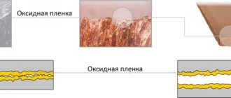
Insulation testing, developed in the early 20th century, is the oldest and most widely used measuring process in modern electrical engineering and is carried out according to government electrical safety standards. This is due to the fact that even without visible damage to the insulation of cable networks, its resistance may become insufficient to protect a person from the effects of high voltage currents.
Principle of operation
Factors contributing to the deterioration of insulation:
- Temperature. Temperature changes from cold to hot, and vice versa, over time cause cracking of the insulation.
- Electric. All cables are manufactured for specific operating conditions. Violations of factory conditions of use can expose the cable to overvoltage with loss of insulation of its protective properties.
- Physical. Damage to insulation due to operational violations or other unlawful actions of maintenance personnel.
- Chemical. Motor oil, dirt and dust can have adverse chemical effects on wire insulation.
- Environment. This factor always affects the protective coating of cables: ultraviolet rays, humidity, snow and natural factors, which must be taken into account by cable product developers.
You might be interested in this Classification of electrical circuits
Resistance measurement
Megger operating principle:
- The voltage for testing with a manual megger is obtained by rotating the crank; the electronic type is obtained by using a battery.
- 500V DC is sufficient to perform testing of systems operating with voltages up to 440V, and the 1000V mode up to 5000V is sufficient for testing high-voltage electrical systems.
- The deflection or current coil is connected in series and allows the passage of electrical current received by the circuit under test.
- The control coil is connected to the circuit.
- A current limiting resistor (CCR and PCR) is connected in series with the control coil to protect against damage in the event of very low resistance in the external circuit.
- A manual megger uses the effect of electromagnetic induction to create a test voltage. As it increases in the external circuit, the deflection of the pointer increases and decreases with increasing current.
- The tester's operation is based on the principle of an ohmmeter. Torque is generated by the megger due to the magnetic field created by voltage and current, similar to Ohm's law. The torque of the megger varies in proportion to V/I: V = IR or R = V / I, unit 1 Ohm.
- The electrical resistance to be measured is connected through the generator and in series with the deflection coil. When the circuit being tested is open, the torque due to the voltage coil will be maximum and the arrow will show “infinity”, which means there is no short circuit in the entire circuit and has maximum resistance in the circuit being tested.
Important! If there is a short circuit, the indicator shows “zero”, which means the complete absence of resistance of the insulating coating.
Safety precautions when measuring insulation resistance
High test voltage can cause damage to electronic equipment such as electronic fluorescent lamp starters, touch switches, dimmer switches, and power controllers. Therefore, such equipment should be disconnected.
Capacitors and indicator or test lamps should also be disconnected because they may cause inaccurate test results.
If any equipment is disconnected for testing, it must be subject to its own insulation test using a voltage that will not damage them. The result must be as specified in the UK standard or be at least 0.5 MΩ if not specified in the standard.
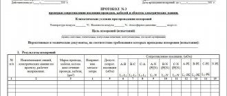
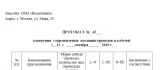
Registration of test results (measurements).
8.1. The results of the inspection are reflected in the protocol of the appropriate form.
8.2. A list of noticed deficiencies must be presented to the customer so that measures can be taken to eliminate them.
8.3. The test and measurement report is drawn up in the form of an electronic document and stored in the appropriate database. The second copy of the protocol is printed and stored in the archive of the electrical measuring laboratory.
8.4. Copies of test and measurement reports must be stored in the archives of the electrical laboratory for at least 3 years.
Absorption coefficient.
The procedure is as follows: from the moment the voltage of the required value is applied in Volts, the values are recorded for 15 seconds and 60. Next are R15 and R60. Be sure to ground before starting and disconnect from the network.
The test is carried out between the windings of the electrical machine and between the windings and the housing. Two separate operations. The coils will need to be connected to each other in series, combining into one circuit. Temperature measurements can be taken at the same time as this test. Perform these measurements indoors at temperatures above 10°C.
R60 = Un / (1000 + Pn / 100),
where Un is the rated voltage of the winding in volts; Pn – total power (in kilowatts for direct current machines or in kilovolt-amperes for alternating current machines).
Well, then the treasured formula for determining the absorption coefficient: Ka = R60 / R15. There are tables that indicate the acceptable values of absorption coefficients for your specific engine model.
Expert opinion
It-Technology, Electrical power and electronics specialist
Ask questions to the “Specialist for modernization of energy generation systems”
Controlling the heating temperature of electric motors Please note: If electrical equipment is designed for 600 Volts, it is prescribed to use a device for 2500 Volts. Ask, I'm in touch!
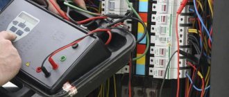
Initial preparation for measurements
Immediately after visiting the owner’s site, specialists do not begin taking measurements; first, they carry out a number of activities aimed at ensuring the safety and accuracy of subsequent measurements. Energy professionals should be well aware that the quality and accuracy of tests performed can be influenced by various external factors. The most important condition for testing wiring is the ambient temperature and humidity. Research cannot be carried out if the temperature in the room has dropped below 5-10 degrees Celsius, since under such conditions the resistance data obtained using meters can be seriously distorted.
Before starting the main research, employees of the energy laboratory visually check the condition of individual sections of the system, for example, in the electrical design of an apartment, to which there is free access. Problems in wiring often arise due to mechanical damage, dust or dirt in certain areas of the electrical circuit. There are often cases when even a superficial inspection of some sections of the network leads to the identification of major damage caused by the owner himself when performing finishing work in the home.