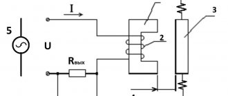
When power goes out for even a few minutes, businesses can suffer enormous losses. And for hospitals this situation is simply dangerous. Most facilities require uninterrupted power supply. To do this, it must be connected to several sources of electricity. Specialists with this approach use AVR.
What is an AVR and its purpose?
Automatic transfer switching or ATS is a system related to electrical switchboard input and switching distribution devices. The main purpose of the ATS is to quickly connect the load to backup equipment. Such a connection is necessary when problems arise with the supply of electricity from the main power source. The system monitors the load voltage and current and thus ensures automatic switchover to emergency operation.
ATS is necessary if there is a spare power source (an additional line or another transformer). If during an emergency the first source is turned off, all work will transfer to the spare one. Using an ATS will help you avoid troubles caused by power outages.
Requirements for ATS
The main requirements for ATS systems are as follows:
- It must have a high rate of power restoration.
- In the event that the main line stops working, the installation must provide electricity to the consumer from a backup source.
- The action is carried out once. Multiple switching on and off of the load, for example due to a short circuit, should not be allowed.
- The main power switch must be turned on using the automatic transfer system. Until backup power is supplied.
- The ATS system must monitor the correct functioning of the backup equipment control circuit.
Application of backup power
A long-term lack of electricity causes a lot of inconvenience for people, and can also lead to a threat to the life and safety of people. Uninterrupted power supply can be ensured from two independent power sources, which is used for consumers of the first category. A special group of the first category is supplied with electricity from three mutually redundant power sources. Such schemes have a number of disadvantages:
- The value of short circuit currents is much higher than with separate power supply to consumers.
- Large losses of electricity occur in supply transformers.
- Complex protective circuit.
- It is very difficult to keep track of power flows.
- Sometimes it is difficult to carry out parallel operation of power supplies due to the presence of previously installed relay protection.
Therefore, there is a need for separate power supplies with fast power recovery. It is this task that is performed by the automatic transfer switch, which connects a separate network or another power source (generator, battery). Backup switchboards are widely used in transport and communications enterprises, in the construction of housing complexes and in other areas of industry.
Typically, an ASU cabinet with an ATS is installed at the entrance to the building, that is, electricians complete the input distribution device with a backup power supply unit. Such equipment can also be installed in separate units, which are assembled at the factory.
Operating principle of automatic reserve entry
The basis of the ATS operation is monitoring the voltage in the circuit. Control can be carried out using any relays or microprocessor control units.
Reference! A voltage control relay (also called a volt controller) monitors the state of the electrical potential. In the event of an overvoltage in the network, the volt controller will instantly de-energize the network.
The contact group, which controls the availability of electricity, plays a major role in the automatic transfer system. In our case it is a relay. When the voltage disappears, the control mechanism receives a signal and switches to power to the generator. When the main network begins to operate normally, the same mechanism switches the power back.
Operating principle of industrial systems
The basic principles here remain unchanged. As an example, we can take an ATS circuit in the form of a standard cabinet. A relay is used here to monitor the state of each phase. If there are problems on one of them with voltage imbalance, you can always switch the load to the remaining line. This will restore the original power supply when problems with the main source disappear.
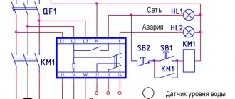
Diagram of a typical industrial AVR cabinet
Designations:
- AB1, AB2 – three-pole protection devices;
- S1, S2 – switches for manual mode;
- KM1, KM2 – contactors;
- RKF – phase control relay;
- L1, L2 – signal lamps to indicate the mode;
- km1.1, km2.1 km1.2, km2.2 and RKF1 are normally open contacts.
- km1.3, km2.3 and RKF2 are normally closed contacts.
Basic options for the logic of ATS operation
ATS system with first input priority
The essence of the operation of this type of automatic transfer system is that the load is initially connected to power source No. 1. When an overload, short circuit, phase loss or other emergency occurs, the load switches to a backup source. When the electricity supply at the first is restored to normal parameters, the load is automatically switched back.
ATS system with second input priority
The logic of operation is the same as that of the previous type of system. The difference is that the load is connected to input 2. In the event of an accident, the voltage goes to input 1. After the voltage on the second source is restored, the voltage will automatically switch to it.
What schemes of operation of ATS exist?
Working examples show the success of using an autostart panel for uninterrupted power supply to a home.
Simple circuits
One of the variants of the ATS circuit shows the switching of electricity to the generator from the main line. The principle of short circuit protection is present here. This ATS is equipped with electrical and mechanical interlocking, which prevents two inputs from starting at the same time.
AVR diagram for home
Designations:
- AB1 and AB2 are two-pole circuit breakers on the main and backup inputs.
- K1 and K2 are contactor coils.
- K3 – contactor acting as a voltage relay.
- K1.1, K2.1 and K3.1 are normally closed contacts of the contactors.
- K1.2, K2.2, K3.2 and K2.3 are normally open contacts.
When automatically switching AB1 and AB2, the operation of the ATS system is as follows:
- Power supply from the main line is normal. When coil K3 is saturated, the voltage relay is triggered, which leads to the closure of K2.2 and K2.3 and the opening of K1.
- Power supply in emergency mode. If there are voltage problems on the main line, K3 is not saturated, the voltage drops below the permissible level, and the contacts return to their original position. Thus, voltage is supplied to coil K1, which causes the position of contacts K1.1 (the role of electrical protection) and K1.2 (which removes the blocking of power supply to the load) to change.
- Mechanical interlock triggered. In this case, a reversing starter is used (if there is one on the design of the electromechanical device).
An example of the operation of two simple automatic transfer switches for three-phase voltage, where, in one case, power supply is carried out according to a one-way scheme, and in the other - according to a two-way principle.
An example of one-way (B) and two-way (A) implementation of a simple three-phase ATS
Designations:
- AB1 and AB2 – three-pole circuit breakers;
- MP1 and MP2 – magnetic starters;
- RN – voltage relay;
- mp1.1 and mp2.1 – group normally open contacts;
- mp1.2 and mp2.2 – normally closed contacts;
- rn1 and rn2 – RN contacts.
Circuit A has two equal inputs to prevent simultaneous switching of lines. The principle of mutual interlocking is used here, as on contactors MP1 and MP2. Thanks to the sequence of automatic switching on AB1 and AB2, it will depend on which line the load will go. If AB1 is triggered first, then the MP1 starter is activated, and the MP1.2 contact is broken, which leads to the blocking of voltage to the MP2 coil. If source 1 is turned off, then the MP1 starter goes to its original position. And PM2 comes into action, which blocks the first starter and transfers the load supply from source 2. You can also switch sources manually using AB1 and AB2.
For the one-way principle of operation, circuit B is used. Its main difference is that a voltage relay (RN) is added to the connection circuit and when operation is restored, it returns the connection to source 1. But at the same time, RN2 opens, which turns off the starter MP2 and closes RN1, which allows you to connect MP1.
Main types of AVR cabinets and panels
ATS panel for two inputs on contactors (starters)
Installing an ATS cabinet on starters is the easiest way to create backup power. This cabinet is the most budget-friendly option for installing an ATS. As a rule, automatic switches are used in ATS cabinets with 2 inputs. They are needed to protect the system from overloads and short circuits. Protection against phase imbalance and voltage surges is provided by a voltage relay. In addition, the relays become the “brains” of the entire automatic transfer system.
An ATS cabinet with two contactors works according to the following principle. Two contactors are connected to the first and second sources, respectively. The first contactor is closed, and the second has an open circuit. Electricity goes through input No. 1.
Attention! In the case when the ATS has priority logic for the second input, the situation will be the opposite: the circuit of the second contactor is closed, and the first one is open.
If the current supply at the first input disappears, but at the second it is normal, then the contacts of the second starter will close and the mechanism will switch to it. As soon as the voltage is restored at the first input, the circuit will return to its original state.
Using a relay, here you can adjust the delay time with which switching from one source to another will take place. The optimal delay is from 5 to 10 seconds; it will protect the system from false triggering of the automatic transfer switch. False triggering can occur, for example, in the event of a voltage dip.
Reference! To prevent both contactors from turning on at the same time, additional mechanical interlocks are used in ATS panels.
ATS panel for 2 inputs on motor-driven machines
They are best suited for use with current ratings of 250-6300A. When the current at the main input disappears, special electric motors receive a signal and charge the springs of the spare switch, switching the load to another input.
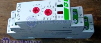
Programmable relay EKF PRO-Relay
The main control of the operating logic is carried out by the EKF PRO-Relay programmable relay. This allows for more flexible implementation of the main functions of the control system.
In this scheme, a programmable relay controls the position of circuit breakers, ensures on-off switching of inputs, with its help time delays for operation of switches are set and changed, and diagnostic functions are performed.
In addition, if necessary, you can change the operation algorithm of the ATS circuit without extra costs and display the necessary information about the operation of the ATS to the upper level via Modbus, although this requires an additional interface module.
PRO-Design is used as software for PRO-Relay. The program can be downloaded for free from the official EKF website.
Also, to download the program you will need an ILR-ULINK cable, which will need to be purchased separately.
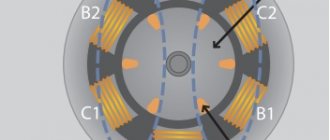
High-voltage circuits with ATS
The operation of automatic transfer switches in high-voltage networks of the 1 kV class has a more complex scheme, although with a similar operating principle, as stated above. All triggering mechanisms do not change here. But in this scheme there are no backup transformers and each bus (Sh1 and Sh2) is connected to its main supply transformer (T1 and T2). The latter can, in certain circumstances, become backup sources with additional load. In normal mode, the CB10 switch is open and the ATS controls the TP via TN1 Ш and TN2 Ш.
When the power is blocked at Sh1, B10T1 is turned off and SV10 is turned on. Both sections or blocks start working from the same transformer. As soon as the source restores its operation, the ATS will reconnect the system to its original position.
Simplified diagram of 110/10 kV transformer substation