Organizations conduct a large number of scheduled inspections. One of these is checking the resistance measurement of the phase-zero loop. It is also organized upon commissioning of the premises. Based on the results of the inspection, the specialist must issue a protocol for measuring the resistance of the “phase-zero” loop with the test results. We will tell you in the publication what information should be in this document.
- Form and sample
- Online viewing
- Free download
- Safely
FILES
Definition of the concept of a phase-zero loop
The circuit includes combined neutral and phase conductors .
In the event of a short circuit between the phase conductor and the neutral conductor, which is connected to the transformer neutral or housing, a circuit appears called a phase-zero loop. The test is carried out to determine the proportionality of the cutoff current of the machine and the short circuit current . This will clarify the shutdown time of the damaged area and identify the likelihood of such a blackout. They measure indicators on a distant section of the highway in order to use the lowest values of the line.
Current loop resistance depends on factors:
- cable cross-section;
- wire length;
- transition resistance values in junction boxes on the route.
Valera
The voice of the construction guru
Ask a Question
Based on the obtained parameters, the probable short circuit current is calculated and compared with the cutoff current of the protective device. The circuit current decreases as the internal resistance of the circuit increases, so the machine may not work. Timely measurement using a loop will prevent an emergency situation.
Preparatory stage
Almost all methods of measuring the phase-zero circuit do not allow obtaining accurate information about such characteristics as ZP and ISC. This is due to the fact that the vector nature of voltage is not taken into account. Simply put, simplified short circuit conditions are taken into account. When testing electrical installations, such approximation is allowed only in cases where the level of reactance does not have a significant effect.
Before you begin measuring the characteristics of the F-N loop, you should first carry out a number of preliminary tests. In particular, check the continuity and resistance level of the protective lines. After this, measure the resistance between the ground loop and the main metal elements of the building structure.
The need to measure F-N resistance
The method allows you to compare the actual resistance measured in practice with the projected indicator included in the planning. If the circuit is installed properly, both values will coincide, which means that the operation of the line will be safe.
Purposes of phase-zero loop measurement:
- checking installation quality to find errors and weak areas;
- safety assessment of automatic protection equipment;
- testing of electrical installations upon delivery and acceptance into operation after reconstruction or installation;
- at the request of regulatory organizations, for example, Rostechnadzor;
- at the request of the owner of the main line or electrical units.
Valera
The voice of the construction guru
Ask a Question
The length of the cable line from the transformer to the consumer outlet is measured in hundreds of meters. There are many connectors in the line design that lose voltage even when installed correctly. Internal resistance measurements are carried out to identify negative areas and enhance protection on them.
How often are measurements taken?
The frequency of readings and calculations is carried out in accordance with the preventive maintenance schedule developed by electrical engineers. The document contains recommendations for maintenance and testing of systems, and is signed by the head of the enterprise.
Recommended inspection periods in accordance with GOST R 50.571 – 2007:
- for electrical appliances and installations operating in areas of increased explosion hazard - once every 2 years;
- if automatic protection fails, an immediate unscheduled check is performed;
- mandatory - during acceptance and commissioning, when putting equipment into operation;
- for standard conditions, after successful completion - once every 3 years.
At the request of the owner or the recommendation of the responsible person regarding technical inspection and monitoring of electrical equipment, such measurements are made more often.
How the network is measured
To understand this, it is necessary to consider a circuit in which there is a consumer connected through a regular outlet. So, as mentioned above, phase and zero are supplied to the socket. In this case, there is a loss of voltage up to the outlet due to the resistance of the main cables and wires. This has been known for a long time; this process is described by Ohm’s formula:
R=U/I.
True, this formula describes the relationship between the magnitudes of direct electric current. To convert it to alternating current, you will have to take into account some indicators:
- Active component of network resistance.
- Reactive, consisting of a capacitive and inductive part.
What does it mean?
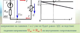
It is necessary to understand that the electromotive force that appears in the windings of the transformer forms an electric current. It loses its voltage when passing through the consumer and the supply wires. In this case, the current itself overcomes several types of resistance:
Circuit Resistance Testers
All modern electrical laboratories have meters. The devices reproduce a fake short circuit on a controlled section of the circuit or inside the unit, then immediately measure the resistance of the phase-phase, phase-zero loop (reactive, active, total electrical resistance).
The device instantly calculates the short circuit current without turning off the protection. This is how they check the correctness of the selected nominal value of the machine or fuse. At the same time, they determine the response time of the protection.
Devices help determine:
- values of transition resistances of switching devices (switches, circuit breakers, fuses, contactors, disconnectors, etc.);
- the exact trajectory of the electric current in the event of an accident (through steel pipes, metal water pipes, circuits, other pipelines with iron walls, grounding cable).
The box of devices has holders in the form of magnets, so they can be quickly fixed to steel walls. Paint on metal does not interfere with retention.
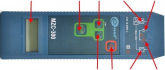
2.1. Measurement procedure with the MZC-300, MZC-303E device
2.1.1 Conditions for performing measurements and obtaining correct results
To start measuring, several conditions must be met. The meter automatically disables the ability to begin measurements (this does not apply to line voltage measurements) if any of the following abnormal conditions are detected: Situation Displayed symbols and warning signals Explanations The voltage applied to the meter is greater than 250V. OFL inscription and long beep. Immediately disconnect the meter from the network under test! The integrity of the PE/N wire is broken. The _—_ symbol is displayed and a long beep sounds. The symbol and sound signal appear after pressing the [start] key. Precautions must be taken as the network under test does not have overcurrent protection! The voltage applied to the meter is too low to measure resistance - less than 180V. -U- is displayed and two long beeps sound. The inscription and sound signals appear after pressing the [start] key. Thermal protection blocks the measurement, which is possible with very intensive measurements. The T symbol appears on the display and two long beeps sound. The symbol and beeps appear after pressing the [start] key. During Auto Calibration, the sum of the circuit impedance and the test lead impedance is very large. Instead of the measurement result, the ]-[ symbol is displayed, the device additionally generates two long beeps. The meter also signals a situation in which the measurement result cannot be considered correct: ¦ If the batteries are discharged, the display shows the inscription bAt alternately with the voltage measurement result. The specified measurement can be made, but the results obtained cannot be the basis for a correct assessment of the electrical safety of the electrical installation under test.
2.1.2 Methods for connecting the meter
Fig.6. Measurement in working chain (LN)
Rice. 7. Measurement in the protective circuit (L-PE) a) TN network (with grounding) b) TT network (with protective grounding)
Rice. 8. Testing the effectiveness of protection of the electrical installation enclosure
The meter is connected to the circuit under test or to the device as shown in Fig. 6, 7 and 8. You should pay attention to the correct selection of measuring tips, since the accuracy of the measurements is highly dependent on the quality of the connections made. A good connection must be ensured and a large measuring current must be allowed to flow continuously. It is unacceptable, for example, to attach a crocodile clip to dirty or rusty elements - they must be thoroughly cleaned or pointed probes must be used for measurements.
2.1.3 AC voltage measurement
Devices of the MZC-300 family can measure AC voltage in the range 0...250V. The device measures the voltage between the measuring sockets L and PE/N. The input resistance of the voltmeter is at least 150 kOhm. The voltmeter mode switches on automatically after turning on the meter's power, and also approximately 5 seconds after: • Measuring the impedance, expected short-circuit current or test lead resistance (during Auto-calibration); • The last time you pressed any of the keys associated with displaying measurement results.
2.1.4 Measuring short-circuit loop parameters
The MZC-300 family of devices uses a method for measuring the impedance of a short-circuit loop by “artificially short-circuiting” the circuit under test through a resistor that limits the amount of measuring current. The voltage at the device sockets is measured immediately before the flow of the measuring current and during the flow of the measuring current, taking into account the vector structure of voltage and current. Next, the processor calculates the total resistance of the short circuit loop, identifies its active and reactive components, as well as the phase angle that will occur in the circuit under test in the event of a short circuit. The limiting resistor has a value of 10 Ohms, and the flow time of the measuring current is 30 ms. The meter independently selects the impedance measurement range. Displaying the measurement result as resistance or current The measurement result can be displayed as the short-circuit loop impedance or the expected short-circuit current. Pressing the Z/I key while one of these values is displayed switches the instrument to display the other. The device always measures the impedance, and the expected short-circuit current displayed on the display is calculated by the formula: where: Uo = 220V is the rated voltage of the network under study, Zs is the measured impedance. Therefore, in networks with a different rated voltage, it is necessary to make an appropriate correction when calculating the short-circuit current. For example, in a network with Uo = 230V, the expected short circuit current will be 230/220 = 1.045 times greater than that displayed on the device. In the following, the term "impedance measurement" will mean taking a measurement and displaying the result as current or resistance.
2.1.5 Performing a measurement and reading the result
The measurement process can be started by pressing the START key at the moment when the meter displays the voltage value on the display. If there is no reason to block the measurement, the device performs the measurement and, depending on the settings made by the User using the Z/I key, displays on the display the value of the impedance or the expected short-circuit current. The remaining components of the measurement result: active resistance, reactance and phase angle can be called up on the display by pressing the SEL key. After the device automatically returns to the voltage measurement mode, the measurement result remains available. It can be brought up again on the display using the SEL key. Impedance, active resistance and reactance are specified up to a value of 199.9 ohms. If in the resistance measurement mode, the readings are more than 199.9 Ohms, the OFL measurement range symbol will appear on the display, and in the short-circuit current mode, the meter will display a very low value symbol UFL. If impedance values of more than 199.9 Ohms are expected at the measurement point and such a result is acceptable for a given electrical installation, then the MZC-ZOZE device can use the RCD function, which increases the measurement range to 1999 Ohms. WARNING: Taking a large number of measurements in a short period of time can generate a lot of heat at the limiting resistor. As a result, the device body may become hot. This is normal. The meter has protection against overheating.
2.1.6 Ground resistance measurement
The MZC-300 family of meters can be used for rough ground resistance measurements. For these purposes, a phase conductor of the network is used as an additional voltage source, which allows creating a measuring current, as shown in Figure 9.
rice. 9. Connection method for measuring ground resistance
The measurement result is the sum of the resistances of the measured grounding conductor, working grounding, source and phase conductor. If the obtained result does not exceed the permissible value for the grounding being tested, then we can conclude that the grounding is performed correctly and there is no need to use more accurate measurement methods.
2.1.7 Safe working practices.
Work on measuring the impedance of the phase-zero loop and single-phase fault currents is carried out according to a permit or by order. The type of work registration is determined by the employee who has the right to issue orders and orders. Persons from electrical technical personnel at least 18 years of age, trained and certified in knowledge of safety regulations and this technique, provided with tools, personal protective equipment, and special clothing are allowed to work. The team must consist of at least two people: - a work supervisor with an electrical safety group of at least III; - a member of a team with an electrical safety group of at least III. When supplying voltage from an external power source, organizational and technical measures must be drawn up and carried out, both at the connection point and at the workplace. Connecting wires, power cable, step-down transformer must be double insulated. It is prohibited to perform work in high humidity, as well as in fire-, fire- and explosive environments and rooms. Based on the measurement results, a protocol of the established form is drawn up. Persons who have committed violations of safety regulations or PTEEP, as well as those who have distorted the reliability and accuracy of measurements, are liable in accordance with the legislation and regulations on the mobile electrical laboratory.
Measurement technique
The verification takes place in two stages:
- external control;
- phase-zero loop measurement.
At the first stage , the power panels are inspected, the correct assembly is checked, and attention is paid to the electrical supply diagram. They determine the current of circuit breakers and fuses, check the external integrity of protective devices, the tightness of the joints of wires with each other and with the circuit breakers.
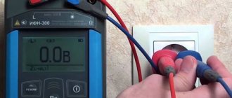
At the second stage, the contacts of the meter are installed in the corresponding sockets and brought to the contacts of the socket on the other side. The voltage value appears on the display. Press the regulation switching key, the built-in contact closes, and a load resistor with a current of more than 10 A is connected in the circuit. The device measures the electric current, calculates the resistance, and displays it on the screen.
Analysis of results
After the measurement, there is the nominal voltage of the circuit and the impedance value. In the event of a short circuit, a single-phase electric current will flow through the main line.
To determine it, use the formula I = Unom/Rp, where:
- I is the strength of the circuit current;
- Unom - voltage (nominal);
- Rп - total resistance.
There are 2 options :
- the cut-off current is less than in the circuit - the machine will not react, only thermal protection will work with an interval of 0.4 seconds (there is a risk of fire);
- The current of the machine corresponds to the norm , so the switch will operate in a timely manner.
The correct choice of ratings of the automatic protection installed in this line is assessed so that it is possible to prevent an accident. According to the PUE standards, a machine is installed that provides an indicator of 1.1 times the rated fault current with an instantaneous breaker.
Filling out the protocol
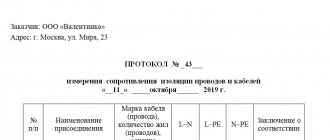
Sample protocol
The form is filled out by a representative of the controlling company.
The protocol indicates:
- name and details of the customer;
- purpose of the inspection (passing tests, unscheduled control, etc.);
- environmental conditions during testing (humidity, air temperature);
- test results in the form of a table, where there are corresponding columns for the name of the equipment, measurement area, type of protective device and all obtained indicators;
- information about the measuring instruments used;
- expert's conclusion.
At the end there are signatures of the employee who carried out the control and the head of the laboratory. Based on the results of the study, the machines are replaced and the network is repaired (if indicated). After this work, new control measurements are organized.
What information should be in this protocol?
The protocol form is drawn up by the executing company. You can use the information presented below as a basis.
So, what should be indicated in the protocol:
- Name of the company conducting the equipment inspection, address, certificate of registration and other data.
- The name of the document, its number and date of preparation.
- Customer of measurement data.
- The purpose of the measurements: acceptance tests, routine inspection of equipment, inspection after replacement of equipment.
- Environmental conditions during measurements: temperature, humidity. The environment has a great influence on the quality of a cable or overhead line.
- Test results. They are presented in the form of a table. The columns in it can be as follows: number in order; Name of equipment; measurement location - protection installation location; data on protection methods (fuse, thermal release, electromagnetic release, etc.); measured circuit resistance; circuit resistance without connecting wires; rated current; does the voltage meet the standards? response time of the protective mechanism.
- What measuring instruments were used for measurements, their error, date of verification.
- Expert opinion.
At the end of the document, the employee who conducted the tests and the head of the electrical laboratory sign.
If the measurement results are unsatisfactory, then it is necessary to carry out repair work on the electrical network, and then organize a new test.
Safety precautions
Tests are allowed to be carried out by workers over 18 years of age who have received all types of safety training. When taking measurements, the team must have 2 people, one of whom has an ES clearance group of at least III.
Safety regulations:
- the work site is fenced;
- work in rubber shoes or stand on a dielectric mat;
- wear rubber gloves; short or rolled up sleeves of overalls are not allowed;
- the handles of the tool must be insulated;
- cannot be measured at air temperatures below +5°C.
After work, they disassemble the measuring circuit, collect the wires, hand over the inspection site to the permitting person, and report to the authorities about the identified malfunctions.
Test timing
Electrical networks and equipment are operated in various modes. Over time, there is natural aging of the cable insulation, deterioration of the properties of conductors due to current overloads, voltage deviations, environmental influences, etc. This necessitates the need to periodically check the integrity of the phase zero circuit.
In accordance with the instructions of the PUE, testing of the “F-N” loop is carried out at least once every 36 months, and for electrical networks operated in hazardous or aggressive environments, at least once every 24 months. Unscheduled inspections are also provided in the following situations:
- when introducing new equipment into operation;
- after modernization, prevention or repair of the existing network;
- at the request of the electricity supplier;
- upon request from the consumer.
Frequency of inspections of electrical equipment of residential buildings