The essence of measurements
Insulation resistance refers to the ability of a material not to allow electric current to pass through itself. Each dielectric, depending on the place of use, has its own regulatory requirements. The frequency of inspection and the required values are indicated in the “Rules for the Construction of Electrical Installations” (PUE) and in the “Rules for the Technical Operation of Electrical Installations by Consumers” (PTEEP).
All types of tests can be divided into three groups:
- carried out by the manufacturer at the factory;
- performed directly on site after modernization or repairs;
- planned according to the requirements of safety rules and regulations.
Possible damage, in addition to manufacturing defects, most often occurs due to operating conditions. This is the effect of overcurrents that cause overheating of the protective shell, the influence of chemical reagents, and mechanical ruptures caused by both installation errors and rodents. The purpose of measurements is to prevent electric shock to humans and ensure fire safety.
Damage to the insulation causes breakdown. This is a situation in which electrical contact occurs between two conductors isolated from each other. For example, between adjacent wires in a cable or when a person touches parts of an electrical installation. Usually, when a breakdown occurs, a hole is burned and a change in the color of the insulating material is observed. The mechanism of breakdown of a solid dielectric is based on an electronic avalanche-like process. It occurs due to the formation of a so-called plasma gas-discharge channel in the material.
Only a specialist who has a knowledge test certificate and an admission group of at least third is allowed to measure insulation if measurements are carried out in a network with a voltage of up to 1 kV, and not lower than fourth when measuring above 1 kV.
After completing the measurement of electrical insulation resistance, the results obtained are processed and a conclusion is drawn about the possibility of further operation of the network. Thus, the ambient temperature is of great importance for the reliability of the result. The normalization of measurements in the PUE is indicated for 20 °C, therefore, if work is performed at a different temperature, then the data obtained is recalculated using the formula: R=K*Riz, where K is the reduction coefficient specified in the additions to the PUE.
Devices used
The instruments used to carry out measurements are conventionally divided into two groups: panel meters and megohmmeters. The former are used with mobile or stationary electrical installations with a separate neutral. The typical design of switchboard insulation monitoring devices includes an indicator and relay part. These meters can operate in continuous mode and be used in 220 V or 380 V AC networks of different frequencies.
In most cases, measurements are carried out with a megger. Its difference from an ordinary ohmmeter is that it works with fairly high voltage values, which the device itself generates. There are two types of megohmmeters:
- Analog . To obtain the required voltage, they use a mechanical generator, which is a dynamo. This type is often called "pointer" due to the presence of a graduated scale and a dynamic head with a pointer. The measurement principle is based on the magnetoelectric effect. The greater the current flows through the coil, the more, in accordance with the law of electromagnetic induction, the needle deviates through a larger angle. The devices are of a simple type with good reliability. Today they are already morally obsolete, as they have significant mass and dimensions.
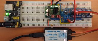
- Digital . The circuit of a modern device uses a powerful signal generator assembled on an integrated circuit (PWM controller) and field-effect transistors. Discrete megohmmeters, depending on their design, can operate from a network adapter or an independent power source, for example, a battery. The results are displayed on a liquid crystal display. The work is based on comparing the measured signal with a reference signal and processing the data in a special unit - an analyzer. The device is lightweight and small in size, but working with it requires certain qualifications.
The main parameter characterizing the operation of the meter is the error of the output result. In addition, its main technical parameters include: resistance limits, the amount of generated voltage, and temperature range.
Test method
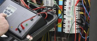
In order to correctly measure insulation resistance, it is necessary to prepare both the test subject and the device itself. The room temperature should be within 25±10 °C with a relative humidity of no more than 80%. Before starting work, you should disconnect the object being measured from the power supply. Make sure that no work is being done on the disconnected line and no one is touching live parts. All fuses, lamps and similar electrical devices must be removed.
Before testing, the residual charge is removed from the disconnected live parts. This is done by connecting them to the ground bus. The contact jumper is removed only after connecting the meter. At the end of the test, the residual charge is again removed by briefly restoring the grounding.
The standard package of the megohmmeter includes three probes. The following are connected to them: protective grounding, line under test, screen. The latter is used to eliminate leakage currents.
The measurement technique can be presented as follows:
- In accordance with the requirements of the PUE for the line, the test voltage is selected. For example, for home wiring, the value is set from 100 V to 500 V. When working with a digital device, you need to press the “Test” button, and on an analog device, turn the knob until the indicator reports the appearance of the required voltage value.
- The linear terminal of the tester is connected to the cable core being tested, and the ground terminal is connected to the remaining wires combined into a bundle. That is, each core is checked in relation to other wires electrically connected to each other.
- Each core is tested relative to the ground, while the remaining wires are not connected to ground.
- If the data obtained turns out to be unsatisfactory, then measurements are carried out separately for each core in relation to all taken conductors in the cable.
- All obtained values are recorded and then compared with the standards of PUE and PTEEP.
It should be noted that if for some reason it is not possible to disconnect the load in a low-voltage network before testing, then the phase and neutral conductors are measured only relative to PE (ground). In this case, the working zeros should be disconnected from the neutral bus. If this is not done, then the data obtained for any wire will be the same and equal to the resistance of the conductor with the worst parameters.
Design and principle of operation
The question of how to test a cable with a megohmmeter arises due to the impossibility of correctly measuring this indicator using a conventional multimeter. The latter does not make it possible to assess the presence of damage to the cable insulating layer and violations of its integrity: even in the case of a sufficiently high rated voltage, the leakage current is too small to be measured with a multimeter.
A megohmmeter makes it possible to determine the resistance of the insulating material separating cable cores, electric motor windings, and other structures in power tools.
Important! These devices are available in different versions. To choose which meter to purchase, you should rely on the features of their functioning, as well as take into account estimates and prices.
Electromechanical megohmmeter
This is the earliest configuration of this device. It includes a current generator powered by rotating a handle, a resistance, an ammeter with a scale, as well as terminals to which the wiring is connected when determining the required parameters: grounding, line and screen. The apparatus can be described as having a simple design and not depending on external current sources. There are also a number of disadvantages: high scale error, the need to keep the instrument body motionless in order to obtain the most accurate measurements.
Electronic megohmmeter
In such devices, the test voltage is generated by an electrical circuit, and measurement is carried out using an analog type meter. This way you can check the resistance without having to turn the knob. It also allows you to measure the absorption index, which describes the moisture content of the insulating material.
Microprocessor megohmmeters
The main advantages of such devices are their compact design and the presence of a digital display. This allows you to combine different functions (assessment of grounding resistance, phase-neutral loop, and others) in one case, which eliminates the need to carry many devices with you.
Valid values
The minimum reading of the measured voltages must be higher than the standardized values. The required resistance value is set by the manufacturer of cable or electrical products, in accordance with the current technical specifications.
Manufactured electrical products are divided into several types and are: general use, power, control and distribution. Products are divided among themselves not only by physical characteristics, but also by design. Their diversity is determined by the environment in which they are used. For example, a cable intended for laying in the ground is reinforced with metal tape and consists of several layers of insulation.
Insulation resistance is measured in Ohms. But due to the large values of the indicator, the prefix mega is always used. The number given is usually calculated for a specific length, most often a kilometer. If the length is less, then a recalculation is simply performed.
For cables used in communications and transmitting low-frequency signals, the insulation resistance must be at least 5 thousand MOhm/km. But for main lines - above 10 thousand MOhm/km. But at the same time, the minimum required value is always indicated in the product passport.
In general, the following insulation resistance standards are accepted:
- cable laid in a room with normal environmental conditions - 0.50 MOhm;
- electric stoves not intended for transportation - 1 MOhm;
- electrical panels containing distribution parts and main wires - 1 MOhm;
- products supplied with voltage up to 50 V - 0.3 MOhm;
- electric motors and other devices operating at a voltage of 100-380 volts - 0.5 MOhm;
- devices connected to an electrical line designed to transmit a signal with an amplitude of up to 1 kV - 1 MOhm.
For cables connected to power lines, a slightly different standard applies. Thus, wires used in an electrical network with a voltage of more than 1 kV must have a resistance value of at least 10 MOhm. For the rest, except for the control ones, the minimum threshold is halved. For control wires, the standard requires a resistance value of at least 1 MOhm.
Insulation control
Insulation resistance is an important parameter of electrical products. The safety of work depends on the parameter being within the established standards. Therefore, it is important to periodically measure the value, identifying deviations in time. In addition, industrial facilities require mandatory frequency of measurements.
In accordance with established standards and regulations, insulation measurements must be carried out:
- for mobile or portable installations at least once every six months;
- for external devices and outdoor cables, as well as in high-risk areas - at least once a year;
- for all other cases at least once every three years.
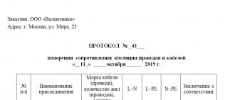
That is, in premises, for example, such as an office, a store, a school, resistance measurements should be performed at least once every 36 months. After completion of the tests, a report must be drawn up indicating the measured data. If the measurements are unsatisfactory, then the electrical section is taken out for repairs until it is brought to the required standards.
High Resistance Insulation Testing: Using Jack G on a Megger
When measuring insulation resistance values (above 1 GOhm), the accuracy of the measurements can be affected by leakage currents flowing along the surface of the insulating material through moisture and contaminants present on it. The resistance value is no longer high and therefore negligible compared to the resistance of the insulation being evaluated. To eliminate surface current leakage that reduces the accuracy of insulation measurement, some megohmmeters have a third socket designated G (Guard). This socket bypasses the measurement circuit and reintroduces surface current to one of the test points, bypassing the measurement circuit (see figure below).
When choosing the first circuit, without using socket G, the leakage current i and the unwanted surface current I1 are simultaneously measured, so the insulation resistance is measured incorrectly.
However, when choosing the second scheme, only the leakage current i is measured. Connection to socket G allows the surface current I1 to be diverted, so the insulation resistance measurement is carried out correctly.
The G socket must be connected to a surface that carries surface currents and is not an insulator such as cable or transformer insulation. Knowing the possible paths for test currents to flow through the element under test is critical to selecting the connection location to socket G.
Safety requirements
One of the fundamental rules when examining insulation is that you cannot begin work without making sure that there is no voltage in the area being measured. The device used for testing must be certified or at least certified.
It is necessary to use only a megohmmeter whose output voltage meets the established standards. So, for networks or equipment with voltages up to 50 V, a tester is used that produces 100 V. Using a device with a lower value will not provide truthful information about the condition of the area, and a larger one can lead to damage.
Measuring resistance with a megohmmeter must be performed only on disconnected live parts, with the mandatory removal of residual charge. In this case, the grounding from the conductive parts is removed only after connecting the tester. The connecting wires are connected using insulating rods. When working, touching live parts, even with dielectric gloves, is prohibited.