Every home has electrical appliances and wiring, the operation of which poses some difficulties. Calling a professional electrician for every slightest problem will cost a pretty penny; it is much easier to solve the problem yourself. For these purposes, you may need a multimeter that measures network parameters. However, the tool is expensive, and purchasing it is not always advisable for use at home. Its functions can be replaced by an indicator screwdriver. What is it and how to use it? How to determine where the phase is and where the zero is?
Principle of operation
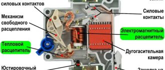
How does an indicator screwdriver work? The appearance of the device is similar to an ordinary screwdriver, but it has an indicator built into the cavity of the handle. The metal part of the screwdriver acts as a probe, and it is capable of reducing the power of the supplied electricity so that using the device is as safe as possible. The device also has an LED, which is located at the top of the handle. In addition, the screwdriver has a contact-type metal plate.
The principle of operation is quite simple - the screwdriver probe touches the electrical conductor, then, passing through it, the current strength decreases significantly, after which the person touches the contact plate with his finger. The circuit closes, causing the light to light up. A screwdriver is necessary to indicate the presence of direct or alternating current in the network.
Determination of zero and phase
Many novice electricians and people who decide to repair electrical appliances on their own are interested in how to find phase and zero with an indicator screwdriver. To do this, you should adhere to the following operating algorithm:
- first the wiring is de-energized;
- the wires that need to be tested must be stripped of the insulating winding;
- after which you need to turn on the electricity;
- Use the probe to touch the wires one by one, while remembering that the circuit must be closed with a finger on the contact plate;
- the wire that, when touched, lights up the light bulb, is a phase of the electrical circuit.
How to find phase and zero with an indicator screwdriver in a socket? To do this, you need to place the probe one by one in the holes of the socket. When a phase is detected, the light will light up. There will be no glow if the screwdriver shows zero. If, when touching both holes of the socket, the light bulb does not light up, this indicates a break in the zero.
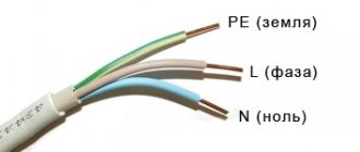
In addition to using an indicator screwdriver, you can determine the phase by the color of the wire:
- the yellow-green wire is ground;
- phase wire color - black;
- zero has a blue wire color.
If the color distribution is not observed, you will need an indicator screwdriver to determine.
Electrician's recommendations
Non-contact screwdrivers are very sensitive, it can react to both phase and neutral, although the real voltage will only be in one wire. Therefore, an ordinary electrician does not need such a screwdriver. However, it can help in checking the quality of cable shielding and the absence of radiation.
In such devices there are three switch positions. Two are provided for remote operation. If you accidentally touch the current-carrying part of the wire with a screwdriver in this mode, the entire electronic part, consisting of transistors and an LED, will burn out.
Electrical appliances surround people in everyday life. Sooner or later, problems and malfunctions arise in any electrical system. These problems are not always worth calling in an experienced electrician; some breakdowns can be fixed on your own. However, to be able to find a fault in the network you will definitely need a special tool, which is worth purchasing in advance.
Checking the serviceability of incandescent lamps
When purchasing another incandescent light bulb, it is important to check its performance right in the store. If there is no appropriate stand, this can be done using an ordinary indicator screwdriver. To do this, you need to take the lamp with one hand by the metal base, and with the probe of the indicator screwdriver in the other hand, touch the central contact on the lamp. If it is working properly, the LED on the device will light up.
Despite the fact that the method is effective, the result may be a failure if the light bulb is depressurized. In this case, the electrical circuit is maintained, but the lamp still will not light up. However, this happens quite rarely.
A light bulb will help you
If all the previous methods do not work, you can try to make a control light yourself. To do this, you need to find a regular incandescent lamp, a socket and two stranded wires, half a meter each.
The cores should be connected to the cartridge connectors. Next, one wire is attached to a piece of metal, and the conductors are tested with the second. If the light comes on, it means there is a phase ahead of you.
This method of determining zero is dangerous. Due to the large number of exposed wires, there is a high risk of electric shock. This method should be used only when absolutely necessary.
Checking the heating element
You can check the functionality of the heating element of the washing machine without even removing it. It is enough to provide access to the contacts; the remaining wires must be disconnected. To check, you need to touch one of the contacts of the heating element with your hand, and the probe of a screwdriver to the other. In this case, the circuit is closed by touching the metal plate on the device. If the lamp lights up, then the heating element is working.
Alternative methods without the use of instruments
If the situation is such that there is neither an indicator screwdriver nor a multimeter, but it is necessary to find out which contact is phase, use a visual method for determining the contact.
On the cable there is often a letter designation of the characteristics of the conductors. So, the letter L is assigned to the “phase”, N to the “zero”, and PE to the “earth”.
Sometimes electricians during installation additionally mark the phase wire with a hanging tag with a designation. But a simpler solution is color coding of wires. Connecting them correctly (in accordance with the standard) subsequently makes the work of electricians easier, allowing them to quickly navigate the wiring.
By wire color
The colors of the wire insulation are selected so that they differ as much as possible from each other:
- The "phase" is often white, black or brown.
- “Zero” - blue and its shades.
- "Earth" - yellow-green.
But the standards for connecting conductors are not always observed. Therefore, for the sake of safety, it is better to check the voltage in the wires, regardless of their visual markings.
Wire marking standard
Using a control lamp
This method is considered the most risky, but it helps out in situations where the usual testers are not at hand. The inspector needs a lamp twisted into a socket from which 2 wires come out. To safely use such a “device,” it is better to attach probes to the ends of the wires and wrap the lamp itself with a protective casing.
You need to touch the metal pipe (or other grounding element) with one lamp tap, and check the contact with the other. If the lamp lights up, then the contact being diagnosed is “phase”.
Conductors can also be identified by exclusion:
- Alternately touch the lamp taps to two of the three contacts that need to be identified. If the lamp is on, it means that the “phase” - “zero” pair is engaged at this moment.
- To determine the phase and neutral conductors, one of the tester taps is used to touch the next of the three contacts being tested. The light goes out when disconnected from the “phase”. But this will only happen if a circuit breaker is installed in the network. If it is absent, the indicator lights up even in the “ground” - “zero” position.
- To identify the “ground”, if a circuit breaker is not installed, remove the ground from the cable and repeat the test. Now the lamp will not light on this conductor.
Assembling a control light at home is not difficult. To do this, you will need 2 conductors connected to the socket, and the light bulb itself screwed into it.
For safety reasons, it is better to use a neon lamp, and electricians recommend attaching probes to the wires - this will secure and facilitate the operation of the “control”.
Since the light bulb method is unsafe, it is best to avoid it.
Control potato
The most unusual method of determining the phase will require 2 wires and potatoes. 2 conductors are inserted into a tuber cut in half at the maximum distance from each other. One is placed over something grounded (a heating system pipe), the other is placed over the contact being tested. After 5-10 minutes, inspect the potato cut. If a spot appears on it, then the conductor being tested is a “phase”. If there is no spot - “zero”.
Checking the voltage in an insulated wire
How does an indicator screwdriver work? Its functionality allows you not only to determine phase and zero, but also to check the voltage in insulated wires. It is not recommended to cut through an unknown wire, as it is often unclear whether it is live or not. In this case, the following manipulations are carried out:
- You need to take the indicator screwdriver directly by the dipstick;
- the metal plate must be attached to the wire;
- if the cable is live, the indicator on the screwdriver will show this.
This method of detection is suitable even for wires that are located under plaster, however, the glow may be less bright.
Zero is missing from the socket. Is it possible to extend the wire from the neighboring one?
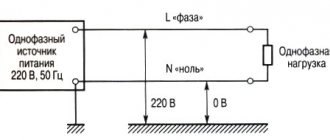
The headache of any electrician is the loss of zero. In its absence, all consumers will be without electricity. The neutral wire appears from the midpoint of the windings of a high-voltage transformer connected in a star. This point is routed to all cabinets and panels, and the grounding bus also extends from this point. The neutral wire is most important for the safety of electrical equipment.
The alternating voltage in the network has a sinusoidal shape. The three phases are shifted relative to each other by an angle of 120*. This is a bit confusing, so these curves are illustrated here. If you measure the voltage with a standard voltmeter, this value between the phase wire and the neutral wire will be 220 V, but this is the average value for half the period. The tester is not an oscilloscope, but only an average meter. In fact, the instantaneous values of peak voltages are greater than 220 V to the square root of 2. In other words, 220 * 2^0.5 = 311 V.
The voltage sine wave says that the average voltage value is 220 V, the peak value is 311 V. Measurements are taken relative to the zero abscissa axis.
The shape of the curve between the two phases is also a sinusoid. The average line voltage is 380 V, and the peak voltage is 536 V.
From the point of view of the average person, it is not clear why when zero is lost, the voltage in the network should increase. Logic dictates exactly the opposite - a complete loss of voltage. And indeed, if you disconnect the neutral wire to your apartment, the light will go out and nothing bad will happen to the equipment. But here we are talking about a zero break at a substation or at floor-to-floor distribution boards.
Let's start unwinding the ball from the very beginning - the active energy meter. At first glance, this is a standard device, but there is a pitfall here. The meter has two windings - voltage, connected between phase and zero, and current, included in the phase break. The voltage between points A and B is 220 V, completely dropping across the voltage winding.
If the zero is broken, the phase will flow through the voltage winding and flow to the consumer. If a consumer takes the indicator and pokes it into a socket, he will detect two phases at once, but the voltmeter will show a stable zero. Perhaps this information will make many people’s brains boil, but there is nothing magical here. It's all about the counter.
If the phase breaks, everything is more logical - nothing will be observed anywhere.
Now about the main thing. When the zero drops to the meters that supply two or more apartments, an interesting process occurs.
Finding a broken wire
The instructions for the indicator screwdriver note the versatility of the device. This is very important and convenient for home use. Having figured out how to find phase and zero with an indicator screwdriver, you can also use it to find a broken wire. If the carrier suddenly stops working, then the first thing you need to do is check the integrity of the electrical circuit:
- You need to make sure that there is no short circuit - to do this, you need to free the carrier from the devices included in it, grab one contact of the plug with your hand, and touch the other with a probe. If there is no light, then there is no short circuit.
- To find a damaged wire, you need to pinch one of the plug contacts with your fingers. Use the probe of the screwdriver to touch the sockets of the extension cord one by one. In which of the sockets there is no glow, a break is observed.
- It needs to be marked with a marker. Then you need to find out the location - where is the phase and where is the zero; once this is done, the plug must be inserted into the socket so that these indicators coincide.
- After that, the metal plate of the indicator screwdriver is used to search for a break. At this point the LED should go out.
The search for a broken wire in the wiring of the house is carried out in a similar way.
The simplest methods for finding phase and zero with a multimeter
A properly organized home grounding circuit eliminates problems. Firstly, PEN insulation is yellow-green in color. It is impossible to confuse it with the brown (red) phase and the blue neutral. It happens that the wiring is laid in violation of the requirements, the colors are mixed up, or missing altogether (aluminum cable). We search for phase with a multimeter using a simple algorithm:
- Let's say an apartment has three wires: phase, neutral, ground.
- We set the multimeter to the AC voltage range of 750 volts and begin testing the wiring in pairs.
- Between the phase and any other wire there will be 230 volts (rms value), the ground-neutral jumper gives approximately 0.
Multimeter
The access panel has at least five wires, three phases. The further process is determined by the imagination of local electricians. Good craftsmen hang stickers A, B, C, indicating the location of the phases. Grounding is yellow-green, neutral is often blue.
Between adjacent phases the voltage is 380 (400) volts. High-rise apartments are sometimes supplied with two phases. Electric stoves with a power above 10 kW try to share consumption. Wiring requirements are reduced. We advise you to immediately take a marker and mark the insulation with the required colors. A house without grounding usually receives two wires: phase, neutral. The substation transformer drives three phases. How many will be in the apartment should be found out.
Problems will begin when there is no wire marking, the phase comes alone. Between dangerous wires the voltage will be... zero!
- Two wires carry a phase, one neutral, they forgot to lay the grounding. There is a round zero between the supply wires; when evaluating the neutral wire, we get 230 volts. The situation looks as if the phase conductors have become neutral and zero. We made a mistake when laying the pipes - what can you do? It is necessary to look for an additional source of support. An indicator screwdriver will do.
- Two wires of one phase, the second pair is grounding, neutral. They will show zero in pairs, crosswise - 230 V. Use a reference point.
There is no probe-screwdriver, with the help of a tester, no matter how you change the wiring, the problem will remain. A reference source that is guaranteed to be grounded is required. Suitable:
- The lightning rod's grounding circuit is often routed along the outer wall of the building, with a strip of steel touching the end of the balcony. Goes vertically down. Grounded, suitable for the chosen purpose with two caveats: grind off the rust layer with a file, carry out the work when the sky is cloudless (beware of lightning).
- The simplest solution is the bathroom faucet.
The pipes are now plastic. But inside there is an excellent electrolyte - water with dissolved hardness salts. Touch the black tester probe to the faucet sleeve and take measurements relative to the fulcrum. Use the sidewalls of copper, brass, and aluminum fittings. There would be water. Indicator screwdriver - On the site, the steel body of the shield, if not grounded, is connected (shorted) to the zero (neutral) wire. Take measurements relative to the selected reference.
- A gas pipe is a taboo for those who want to ground it; it is at zero potential and comes into contact with the ground. If you find chips of paint, use the accessory for the purpose (it is forbidden to cut off the paint yourself) to identify phases, neutrals, and grounding.
- For the reasons described above, batteries made of cast iron and aluminum have become recognized as a good reference point. The main thing is to ensure close contact. How to check? Call two points of the body. Resistance is units of ohms - the norm. Provided the heating is on. According to regulations, the pump body is grounded, the probability of error is low.
- It is not recommended to use sewer pipes as a reference grounding source. Conductivity conditions are determined by the number of... drains.
Due to the variety of methods and unreliability, it is recommended to conduct tests before starting serious work. Measure the potential between the indicated reference points and the phase of the socket. Is the distance between the landmark and destination point large? We take an extension cord. The power filter for a personal computer is especially good, equipped with a characteristic backlit button. The phase is on the left, the left pin of the plug (depending on which side you turn) is marked with a marker.
Then we call it with a socket (without power, of course), and make a mark on the desired side. Let us explain, you can do without this; it’s better to put aside jokes with electricians. All that remains is to find the phase using the M890S. We set the range above 380 volts (between two phases), and begin to measure the potential difference between the terminals and the shield. We believe that the further algorithm is clear.
Electronic indicator screwdriver
You can find phase and zero using either an indicator screwdriver with an LED or an electronic one. The only differences are in their design. The electronic indicator screwdriver can be either with or without a liquid crystal screen.
Instead of a light signal, such a device notifies you of the presence of voltage with an audible signal. In addition, the great advantage of such a device is the display of voltage information on the LCD screen, if available. The operating principle of the electronic device is the same as that of a conventional indicator screwdriver.
Functionality check
Before you determine where the phase is and where the zero is, you need to check the functionality of the screwdriver itself, since it, like any other device, can be faulty. To do this, you should pay attention to the following nuances:
- The device body must maintain its integrity. Working with electricity requires good insulation without damage.
- For accuracy of readings, you should check the screwdriver. To do this, touch the conductor with the probe, which is 100% energized.
- If you use a battery-powered product, you need to replace them promptly.
Safety when using a screwdriver is extremely important, therefore, if a malfunction is detected, it is recommended to purchase a new device. The cost varies from 50 to 1000 rubles. depending on modification.
Determination using a multimeter
Position of the measuring range switch on a multimeter
Any home electrician should have a multimeter in his toolbox. This is a universal tester that allows you to check the performance of electronic components, measure voltage and current, and also test circuits. An inexpensive and high-quality device with simple functionality can be bought for 300-500 rubles. Professional electricians use more expensive devices with additional options and minimal error.
There are two types of multimeters based on the way they work - electronic and analog. Pointer or analogue is a simple device with an arrow. A digital multitester displays values in numbers. The determination method is the same for both types of devices.
Rules for working with a multimeter:
- Measurements cannot be taken at high humidity.
- Defective probes are not used.
- The measurement limit must exceed the measured value.
- When taking measurements, it is forbidden to turn the knobs or set other limits.
Currently, digital multimeters are actively used. The verification algorithm may differ.
Wiring of three wires without markings
Phase search by exclusion method
You can select the exclusion method. To find the phase, the multimeter should be assembled and the probes should be placed on the left and right - black in the COM connector, red in the voltage measurement connector. The switch should be placed in the AC voltage sector V~ or ACV. The arrow selects the voltage limit - it must exceed the network voltage. On the tester you can see values of 500, 600, 750 W depending on the model.
Then voltage measurements are taken between the stripped conductors. There may be 3 options:
- Between zero and phase there should be a voltage close to the mains 220 V.
- There can also be 220 V between the phase and the ground. If the line is protected by an RCD system, the machine may trip. If there is no RCD or there is a minimum leakage current, the displayed voltage will be within the nominal error.
- There is zero voltage between zero and ground.
After the measurements are completed, the tester is turned off, the ends of the conductor are insulated and marked. It can be done using colored tape or adhesive tape with appropriate inscriptions.
Checking the contact in the socket by directly measuring the voltage
Determining the phase using a multimeter
The multimeter is prepared, and a control measurement of the voltage in the socket is made. This allows you to verify that there are no breaks in the line and that the device itself is working. If the numbers shown on the display are correct, the connection is correct.
The red probe needs to touch the conductor being tested. When checking the socket, the probe is placed in the socket. If you are testing the stripped end of the cable, it is recommended to connect via an alligator clip. The second probe touches the fingers. Readings are taken on the display. If the black probe is set to zero, the voltage will be zero or close to zero. When it hits a phase, the voltage will reach tens or hundreds of volts.
Touching the probe with your hand is safe in this measurement. The device was previously tested for serviceability, so a person will not be shocked by an electric shock that is life-threatening. But even despite the safety of the procedure, not everyone can cross the psychological barrier. Then you can touch the plaster, ceiling or wallpaper with the probe. They have little moisture, so the readings on the tester will be visible. They will be lower than the required value, but it is realistic to determine the phase in this way. You can also use any grounded device (heating radiator, water supply) or a metal frame without grounding as the second contact.
Search for zero and ground
Voltage measurement mode on a multimeter to determine the phase
Determining the phase is not difficult. It is more difficult to distinguish zero from ground. There are different determination methods, but they are all unreliable. You can accurately determine the purpose of the core using professional instruments from the arsenal of specialists.
One way is to check with a multimeter. If the RCD is triggered, it can be judged that the tester was connected between phase and ground. Upon contact with the phase and neutral conductors, the protective device does not operate. This is due to the fact that when measuring between the phase and grounding conductors, a small leakage current is formed, which may not be enough to trigger the protective system.
The second method is calling using a multitester. The multimeter switches to the resistance measurement state. The range can be set to 200 Ohms. Be sure to turn off the voltage on the panel. After this, you should check the voltage between the conductors and the grounded object. The resistance value on the grounding conductor should be lower than on the zero one.
The described methods are approximate and do not provide a 100% guarantee of the correct determination of zero and ground. Connections may be different, and the difference in measurements in all cases is minimal. If necessary, special determination devices should be used.
Security measures
When working with the device, the following safety precautions must be observed:
- The screwdriver should not be disassembled; only the batteries, if any, should be replaced.
- The use of a damaged screwdriver is strictly prohibited.
- Do not use the device without a screw.
- When the probe comes into contact with electricity, do not touch the exposed part of the device with your hands.
- Do not use the device at voltages higher than those indicated in the technical specifications.
In order to find out whether phase or zero is lit on the indicator screwdriver, you need to follow all the recommendations outlined above. At the same time, it is important to monitor the serviceability of the device and not neglect the rules for the safe use of an indicator screwdriver.