Author: Evgeny Zhivoglyadov. Date of publication: February 19, 2014. Category: Articles.
Drying of transformer insulation can be carried out in one of the following ways: - in a stationary drying cabinet under a vacuum of 700 - 750 mm Hg; - in its tank, losses in steel of the tank with or without vacuum; - zero sequence current in its tank; — infrared radiation outside the tank.
Drying the active part of the transformer in a chamber without vacuum
With this drying method, the active part of the transformer is placed in a well-insulated chamber (Figure 1), which is made of wooden frames and panels covered with plywood sheets with an air gap. The inside of the chamber is sheathed with sheet asbestos and on top of it with sheets of roofing steel. The joints between the panels are insulated with asbestos. Another camera design can be used. The distance between the walls of the chamber and the active part of the transformer must be at least 180 - 200 mm. An exhaust hole is made at the top of the chamber to remove vapors released during drying. The active part is most often heated using blowers. You can also use electric ovens or steam coils.
Figure 1. Drying a transformer in a chamber using a blower 1 – fan; 2 – heater; 3 – spark arrester; 4 – insulated chamber; 5 – adjusting gate; 6 – thermometers; 7 – thermocouples in the winding
To speed up drying, it is advisable to use two blowers, supplying hot air from them into two holes located in the lower part of the chamber, along its diagonal. With one blower, for uniform drying, air from it should also be supplied to two holes diagonally in the chamber. A fabric filter is installed on the suction pipe of the blower, and a spark arrester (metal mesh) is installed on the pressure pipe. The hot air stream should not be directed at the winding or yoke insulation.
The amount of air Qb, m3 supplied to the drying chamber in 1 minute should be 1.5 times the volume of the chamber Qcam.
The power of electric blower furnaces, kW, should be equal to:
P = 0.07 × Qв × Gр × (t2 – t1) ,
where Gr is the specific heat capacity of air, taken equal to 0.273 cal/kg×deg; t1 – ambient air temperature, °C; t2 – temperature of air entering the chamber, °C.
Example. Chamber volume 2 × 3 × 2 m = 12 m3, t1 = 20 °C, t2 = 100 °C. Determine the power of the blower.
Volume of air supplied to the chamber:
Qв = 1.5 × Qkam = 1.5 × 12 = 18 m3.
Blower power
P = 0.07 × 18 × 0.273 × (100 – 20) = 18.7 kW.
The temperature of the incoming air and the temperature in the chamber should not exceed 105 °C. The temperature of the exhaust air should not be lower than 80 – 90 °C. At a lower temperature of the exhaust air, the chamber should be insulated more thoroughly.
When the insulation temperature of the active part of the transformer rises above 105 °C, the temperature of the incoming air should be reduced by increasing the opening of the blower gate, and if it is fully open, periodically turning it off.
For transformers with a voltage of 35 kV and higher, after heating the active part to a steady-state temperature on the winding (105 ° C), it is advisable to speed up drying by quickly reducing the temperature of the outer layers of insulation by turning off the electric furnaces of the blower and supplying cold air (use the so-called thermal diffusion). When the chamber is rapidly cooled, the inner layers of insulation do not have time to cool down much and their temperature will be higher than the temperature of the outer layers. Thus, the decrease in temperature across the layers will coincide with the direction of moisture removal, which will significantly speed up the drying process. The temperature of the internal layers can be approximately considered equal to the temperature of the magnetic core. The temperature difference between the outer and inner layers of insulation must be at least 15 - 20 ° C and last for 15 - 25 hours. It is recommended to reduce the temperature on the outer layers of insulation to 50 – 40 °C and on the magnetic core to 70 – 65 °C. After the end of the thermal diffusion cycle, the active part is heated to the previous temperature and the insulation resistance values before and after thermal diffusion are compared. Depending on the results obtained, a decision is made to apply a repeated thermal diffusion cycle or to terminate drying.
After drying, the active part is inspected (pressing the windings, tightening fasteners, etc.), which is then lowered into the tank and filled with oil.
Connection diagram for electroosmotic drying of transformers
Not all existing drying methods have a favorable effect on the components of the transformer. For example, the widespread use of drying ovens entails a number of difficulties.
Firstly, such ovens consume a huge amount of electricity. Secondly, the drying process takes a long time - up to ten days. The time required for drying depends on the size of the transformer and may increase.
Among other things, oven drying has a negative impact on the condition of the device. The service life of the transformer is significantly reduced due to the fact that high temperatures negatively affect its elements.
The saving technology for the safety of the device was the use of the principle of electroosmosis. It is based on the movement of liquid through porous diaphragms or capillaries by applying an external electric field. Without allowing heat, the device eliminates moisture by generating small electrical impulses.
With a fairly light weight of the device (some weigh a little more than a kilogram), the drying process is greatly simplified.
Drying a transformer by losses in a steel tank
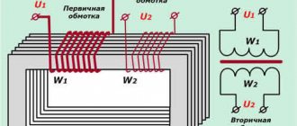
With this method, a magnetizing winding is wound onto the transformer tank, creating an alternating magnetic flux. From the action of the magnetic flux, eddy currents appear in the walls of the tank, which heat the tank and the active part of the transformer located in it.
To reduce heat loss to the environment and speed up drying, the lid and walls of the tank are insulated with fire-resistant materials: asbestos sheets, asbestos sheets, fiberglass mats, and the like. Electric furnaces are installed under the bottom of the tank with a power selected at the rate of 1.5 - 3 kW/m2. The space between the bottom of the tank and the floor of the room is also insulated. Transformers with a power of up to 1000 kV×A can be dried without insulating the tanks.
To reduce the fire hazard, any remaining oil is removed from the tank.
All openings in the lid and wall of the tank that are not used for ventilation, including the openings of the inputs that are removed for drying, are closed with plugs. There must be one measuring input for each winding. For this purpose, both working all-porcelain bushings and any locally available bushings, including those for voltages up to 1000 V, can be used.
For transformers with removable radiators, these radiators must be removed. On tubular tanks, the magnetizing winding can be placed both on top of the pipes and under the pipes. In the latter case, the pipes must be carefully insulated, since otherwise moisture will condense in cold pipes, which, flowing into the tank, will significantly slow down drying.
| Figure 2. Power supply circuit for the magnetizing winding |
If the tank is not insulated, then in order to avoid damage to the wire insulation, the magnetizing winding is made with bare wire, fixed to asbestos-cement racks or wooden slats. Thermal insulation is laid between the wooden slats and the tank. The turns of the bare wire are located at such a distance from each other that when the wire lengthens and sag from heating, a short circuit between the turns is prevented. If the tank is insulated, the magnetizing winding, made with an insulated wire, can be applied directly to the thermal insulation. The turns of a single-phase winding are laid along the entire height of the tank. For more uniform heating of the tank, the coils in the lower and upper parts of the tank should be located more often than in the middle part of the tank. The turns of all three phases with a three-phase magnetization winding are located along the entire height of the tank in one direction at the same distance from each other. For greater effect, the middle winding is connected opposite to the top and bottom (Figure 2). The active part with thermocouples installed on it is lowered into the tank, which is closed with a lid. Wires from thermocouples are passed into the connector between the tank and the lid or through a hole in the lid between two rubber gaskets stacked on top of each other. Each of the windings is connected to its own measuring terminal.
If drying is carried out without a vacuum with natural ventilation, then an exhaust pipe 1 - 2 m long, 25 - 75 mm in diameter is installed on the transformer cover above one of the holes.
To prevent moisture from condensing in the pipe and flowing into the tank, the pipe must be insulated. It is necessary to install a vessel under the pipe inside the tank to collect moisture in case moisture condensation does occur.
At the bottom of the tank, diagonally from the location of the pipe, open the oil drain valve or the plug in the bottom of the tank.
When drying with tank ventilation with heated air, a piece of steel pipe with an induction winding or a nichrome spiral wound on it is bolted to the flange of the oil drain valve. Air heating can be carried out without applying an induction winding and spiral to the pipe, if this pipe is placed under the turns of the magnetizing winding.
When drying with forced ventilation, a pressure pipe from a fan or blower is connected to the oil drain valve, the hourly capacity of which must be at least equal to the volume of the transformer tank.
If the transformer is dried under vacuum, the tank cover is installed on a sealing gasket and tightly bolted to the tank. A condensate column or vacuum pump is connected to one of the holes on the tank lid through a check valve or valve. A check valve or valve is necessary to prevent water or oil from being sucked into the tank from the pump, as well as to remove the air leak curve. A vacuum gauge is connected to the tank cap or vacuum line between the cap and the valve.
It is advisable to have high-capacity vacuum pumps (the hourly pump capacity should be at least 50% of the volume of the transformer tank). Table 1 shows the brands and basic data of vacuum pumps used for drying transformers.
Table 1
| Pump | Productivity at atmospheric pressure, m3/h | Ultimate vacuum, mm Hg. Art. 1, not lower | Quantity of oil VM-4, cm3 | Dimensions, mm | Engine power, kW |
| VN-1, spool valve VN-2, spool valve VN-4, spool valve VN-6, spool valve VN-494, vane rotor VN-461, vane rotor RVN-20, vane rotor RMK-1, water ring RMK-2, water ring RMK-3, water ring RMK-4, water ring | 66 25 212 557 0,75 3 12 90 250 690 1620 | 3000 3000 1000 1000 1000 1000 1000 680 700 736 736 | 3800 2000 17000 55000 1500 2400 2400 2400 2400 2400 2400 | 910 × 625 × 605 690 × 560 × 490 1635 × 875 × 1420 1905 × 960 × 1975 420 × 325 × 235 670 × 415 × 292 525 × 445 × 330 525 × 445 × 330 525 × 445 × 330 525 × 445 × 330 525 × 445 × 330 | 2,8 1,7 7,0 20,0 0,15 0,37 0,37 4,5 10,0 29,0 70,0 |
1 For pumps of type VN and VZN, the residual pressure is given; for RMK – vacuum
When drying transformers under vacuum with air suction, it is desirable to have pumps of the RMK type, since in such modes they work more reliably than pumps of the VN or RVN type.
Single-phase winding calculation
Number of turns:
(turns),
where (V) is voltage; (m) - tank perimeter; (-) – coefficient whose value is equal to: at =1.5 A =1.6; at =2.5 A =1.5.
For a three-phase winding, the calculation is as follows (see diagram of a three-phase winding in Fig. 8).
The winding consists of three separate phases. The number of turns of the first and third windings is equal, the second winding has a slightly smaller number of turns:
(turns);
(turns);
where the designations are the same.
The currents in the windings are calculated as follows: for a single-phase winding
(A);
for three-phase winding
(A).
Fig.8. Transformer induction heating
is taken equal to 0.7 if the winding is laid directly on the tank without an air gap; 0.35 - if an air gap of 20-40mm is provided. Voltage: for single-phase winding - 220 V; for three-phase winding - 380 V.
Low power factor can be compensated by shunt capacitors, the value of which is calculated by the formula:
(uF),
where (V) is the winding voltage.
Table 9 provides examples of winding implementation.
Table 9
| Transformer, kVA/kV | Winding voltage, V | Number of turns, units | Winding current, A | Consumption power | Number of phases in the winding | |
| kW | kVA | |||||
| 100/6 | 220 | I30 | 22 | — | 44 | 1 |
| 1000/10 | 220 | 102 | 46 | — | 10 | 1 |
| 10000/35 | 220 | 65 | 104 | — | 23 | 1 |
| 40000/110 | 380 | 52 | 160 | 40 | 61 | 3 |
| 90000/400 | 380 | 10 | 765 | 185 | 490 | 3 |
| 123000/400 | 380 | 10 | 700 | 225 | 450 | 3 |
Figure 9 shows a diagram of drying in its own tank under vacuum: B - filter for cleaning the sucked air; Tr—transformer tank; cool.col. — a cooling column in which condensate accumulates; vac.us. — vacuum pumps.
Fig.9. Vacuum drying of a transformer in its own tank
Drying a transformer with zero sequence current
With this method, drying is carried out due to the heat generated in the rods and structural parts of the magnetic circuit and in the transformer tank from eddy currents under the influence of an alternating magnetic field. The magnetic field is created by the working windings of one of the voltages of the transformer, connected in such a way that the magnetic fluxes in all the magnetic cores coincide in magnitude and direction.
If a three-phase transformer uses a star-connected winding for heating, then the voltage is connected between the phase terminals connected together and the zero point; if the winding is connected in a triangle, the voltage is connected to the triangle gap (Figure 3). For this purpose, the triangle is soldered at one point and the ends of the open triangle are brought out to the cover through working or specially installed leads.
| Figure 3. Circuit diagram for connecting the windings of three-phase transformers for drying them with zero-sequence currents. a – when connected into a star; b – when connected into a triangle | Figure 4. Schemes for connecting the windings of single-phase transformers during drying with zero-sequence currents. a – windings with the same winding direction; b – windings with different winding directions |
Windings not used to create a magnetic field must be open-circuited. The free winding connected in a triangle must be soldered at one point. The soldered ends should be insulated. Figure 4 shows switching circuits for single-phase transformers when drying them with zero-sequence currents. Factory connections between the coils are unsoldered, and the specified circuits are implemented using temporary jumpers. In preparation for drying, the insulation resistance of the tie rods should be measured. Violation of the insulation can lead to unacceptable overheating during drying.
Table 3 shows experimental data on drying transformers with zero-sequence currents.
Table 3
| Transformer | Input voltage U0, V | Current I0*, A | Heating power | Note | ||
| Type | Voltage, kV | kW | kVA×A | |||
| TM-50/6 TM-100/6 TM-180/6 TM-180/10 TM-320/6 TM-320/6 TM-5600/35 ODTG-20000/110 TMG-7500/110 | 6/0,38 6/0,38 6/0,38 10/0,38 6/0,38 6/0,38 35/3 110/35/10 110/35/6 | 43 36 380 36 25 220 345 230 380 | 72 136 12,2 216 240 27 96 200 85 | 1,5 2,4 2,36 3,5 3,3 3,3 15,12 26 – | 3,1 4,9 4,64 7,8 6 5,94 33,12 46 32,4 | Power supply from the LV side according to the scheme of Figure 3, a Power supply from the LV side according to the scheme of Figure 3, a Power supply from the HV side according to the scheme of Figure 3, a Power supply from the LV side according to the scheme of Figure 3, a Power supply from the LV side according to the scheme of Figure 3, a Power supply from the HV side according to the diagram in Figure 3, a Power supply from the LV side according to the diagram in Figure 3, a Power supply from the LV side according to the diagram in Figure 3, b Power supply from the LV side according to the diagram in Figure 3, a |
* the values of currents flowing through the supply wires are given
Before starting drying, before lowering the active part into the tank, it should be put under the voltage at which drying will be carried out for control heating for 30 minutes in order to identify local overheating of the structural parts of the magnetic circuit. If unacceptable overheating is detected, the cause that caused it must be eliminated (eliminate a short-circuited circuit, etc.).
Vertical tie rods, since they shunt the magnetic flux, can have a high temperature in the middle part of about 140 - 180 ° C. But this is not dangerous for winding insulation, since the studs are located at a sufficiently large distance from the insulation. The transformer tank must be carefully insulated. Electric furnaces should be installed under the bottom of the tank.
Carry out the drying mode as for drying with losses in the steel of the tank.
When carrying out drying with zero-sequence currents, it is necessary to take measures to prevent the possibility of touching the inputs to which voltage is applied, as well as the inputs to which the second, free, winding is connected. To do this, the conclusions must be fenced. When measuring insulation resistance, power must be removed from the windings.
Use of special drying installations
In addition to the above methods for drying transformers, special installations are used for the same purpose. For example, the use of an oil mobile station (SMS) is widespread.
There are special technical requirements that make the installation efficient and safe:
- transformer voltage should be 110-1150 kV;
- The tank of the device can withstand a pressure of 26 Pa.
The installation is based on a metal car containing pumps, vacuum valves, a refrigeration unit and other devices that make the mechanism work efficiently. To connect the SMM to the transformer, a flexible vacuum line is used.
Drying power transformers with infrared radiation
For infrared drying, the active part should be installed indoors under an exhaust ventilation hood. Thermocouples are installed on the removable part. To eliminate errors due to direct irradiation, thermocouples should be covered with keeper or taffeta tape. Stands with lamps are installed around the active steel so that both the windings and the cores not covered by the windings are uniformly irradiated.
Special lamps of types ES-1, ES-2, ES-3 are used as a source of infrared radiation for drying transformers. These lamps have a power of 250 and 500 W at a voltage of 120 and 220 V. For these lamps, 80–90% of the supplied electricity is converted into thermal radiation energy. In the absence of special lamps, ordinary incandescent lamps can be used. To direct the radiation flux to the winding, these lamps are placed in reflectors. When drying with 250 W lamps, they should be located at a distance of 190 mm from each other and at a distance of 300 - 320 mm from the removable part.
To speed up drying, it is recommended to periodically, every 30 minutes, blow the active part with outside cold air for 15 minutes, resulting in a large temperature difference and faster removal of released water vapor.
Table 4 shows experimental data on drying transformers with infrared rays.
Table 4
| Transformer power, kVA×A | Distance, mm, between | Number of lamps per 250 W, pcs. | Installation power, kW | Drying time, h | Note | |
| lamps and active part | neighboring lamps | |||||
| 100 180 320 560 1000 | 350 320 320 320 320 | 190 190 190 190 190 | 24 30 42 50 50 | 6 7,5 10,5 12,5 12,5 | 18 20 22 28 34 | – – With airflow With airflow With airflow |
Comparing the considered methods, the following conclusions can be drawn.
Drying in a special chamber without a vacuum is uneconomical due to large losses of thermal energy with heated air escaping into the atmosphere, takes longer compared to other methods and is used mainly for transformers with a power of up to 5000 kVA × A and voltage up to 35 kV inclusive.
Drying in your own tank, heated by losses in the steel of the tank, is somewhat longer than methods of heating with zero-sequence currents or infrared rays. However, with this method, the magnetizing winding is powered from a standard voltage network and the danger of local overheating is eliminated, since the tank heats up the most, the temperature of which can be easily controlled. Drying can be done both at atmospheric pressure and under vacuum, while when drying with infrared rays, vacuum is eliminated. Due to its versatility, this drying method has become most widespread in installation and operating conditions. Drying in a tank with heating by zero-sequence currents is economical, does not require a magnetizing winding, and has a shorter duration compared to the method of losses in the tank, since the winding is heated from the magnetic core to the outer layers of the winding, that is, in the direction of removing moisture, which speeds up the process drying. The disadvantages of this method are the need to have a non-standard voltage to obtain the required zero-sequence currents and the possibility of local overheating inside the transformer.
Drying with infrared rays is used mainly for low-power transformers.
Operating principle of the Sukhovey oil station
Transformer drying plant
type “Sukhovei” consists of two adsorbers and lower and upper compartments. A blower is installed in the lower compartment as a source of compressed air. Through the collector, it alternately supplies dry air to the adsorbers, each of which contains 190-200 kg of zeolite. This mineral has a very high level of moisture absorption. In addition, it can be regenerated and reused. To do this, before feeding into the installation, zeolites are pierced with hot air.
Through adsorbers, dry air enters the stove, where it is heated to a temperature of 400-420 ⁰C and flows from the top of the equipment to the bottom. From there it goes outside through the outlet valve.
The unit is also equipped with 5 micron fine filters. It is this value that is mandatory to meet the technical specifications for air drying. The dew point temperature is -70 ⁰С.
Both installations from GlobeCore – “Frost” and “Sukhovey” - are designed for drying transformer insulation. The main difference in their use can be considered the fact that the first is designed to dry moisture that has already penetrated into the windings of the magnetic circuit, and the second is to prevent it from entering the transformer tank during its depressurization.
Control heating of the transformer
Control heating or drying of transformers can be performed by induction losses in the steel of the tank, direct current, short circuit or zero-sequence current.
To warm up medium and large transformers, the direct current heating method is most often used. Compared to the induction loss method, it is less labor-intensive, more economical in energy consumption and allows you to constantly monitor the temperature of the windings.
Drying of transformers using a “Sukhovei” type installation from GlobeCore
The “Sukhovey” type installation is used for installation, repair and maintenance of power equipment. Basically, transformers are transported to the installation site in a disassembled state, and there they are assembled and connected to the power supply network. In order to prevent moisture from penetrating into the windings of the magnetic circuit when the transformer is depressurized during its insertion into the power line, a “Sukhovey” installation is connected to it. It supplies hot air to the tank, thus preventing moisture from penetrating the magnetic circuit windings. This installation is also used when oil is drained from a transformer during a planned or repair depressurization of equipment.