To begin with, I want to say right away that for comfortable work related to crimping, it is advisable to use a tool like this:
And to strip the cable it is advisable to use:
If the above is not available, then you can use a knife and hammer
And of course you will need connectors and cable
Crimping twisted pair
To crimp a twisted pair cable (Internet cable), you will need RJ-45 connectors
If you are using an 8 core cable. 8 cores are used to obtain a speed of 1 gigabit over the network. Then the layout is as follows:
From left to right.
- 1) White-orange 2) Orange 3) White-green 4) Blue 5) White-blue 6) Green 7) White-brown
 Brown
BrownHere's a great image I found on the Internet:
I also want to note that this pinout is straight. And it is used in overwhelming cases. And there is also cross pinout. It was used to connect exactly two PCs. This is no longer the case today. Yes, and modern routers and switches can turn the cross into a straight cable. I'll provide the pinout just in case. In case someone needs it
- 1) White-green 2) Green 3) White-orange 4) Blue 5) White-blue 6) Orange 7) White-brown
BrownIf you are using a 4 core cable. Then the layout is as follows:
From left to right.
- 1) White-orange 2) Orange 3) White-green 4) Empty 5) Empty 6) Green 7) Empty
EmptyIn this layout, you can use any pairs of colors, the main thing is that the cores in different connectors were in their places.
Telephone cable cable crimping
To crimp a telephone cable, you will need RJ-11 or RJ-12 connectors
For a home, as a rule, RJ-11 with 2 cores is sufficient. You can put any pair there. The main thing is that the connectors are in the correct ports.
For example:
- 1) White orange 2) Orange
For an office where there are IP phones or digital phones, use RJ-12 with 4 cores. You can also put in any pair there.
For example:
- 1) White-orange 2) Orange 3) White-green 4) Green
Remember how the numbers are located. When connecting the outlet, they will help us navigate
Now let's look at the sockets
How to connect an outlet to a router
We have already figured out how to crimp the connector. Now you need to connect the socket on the other side of the cable
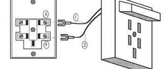
Here's the outlet:
You need to use pinout B in it, and just plug the wires of the corresponding color there
Making an extension cord from a double RJ-45 socket
And finally the RJ-12 socket
Please note that in this socket the guides can be installed in any order
Everything is more than clear here
- 1) If you need to connect a home phone with an RJ-11 connector. Then we connect 2 wires (any) to the 2nd and 3rd wires in the socket 2) If you need to connect a home telephone with an RJ-12 connector. Then we connect 4 wires to all the wires in the socket. Here you need to connect
I won’t describe in detail how to connect the split or how to make an extension cord from such a box. Because everything is clear in the diagram
Despite the fact that the world has almost completely switched to cellular communications, wired telephony still occupies a huge market share. Moreover, directly with its help, Internet access using ADSL and SHDSL technologies is organized in small towns and rural areas. And while the crisis is gaining momentum, there is no need to wait for the transition to fiber optics. At the same time, very often in residential buildings, as well as in various institutions, room wiring is in an unsatisfactory condition: the telephone cord is pinched by chairs, crushed by heels, cats, dogs and even drunk people chew it (this is not a joke, but a real case from practices). Therefore, at some point, the question arises of replacing the wire with a new one, for which they usually call an installer and pay money. All this can be done without the help of others, the main thing is to get a suitable tool and purchase a wire of the appropriate length. But very often everything comes up at the moment when it is necessary to crimp the telephone cable into the RJ-11 connector. We will talk about this procedure at the moment.
What do we need?
Firstly, the telephone cable itself is 2- or 4-wire. Personally, I don’t like the SHTLP telephone cable (aka CLT) due to the fact that I didn’t live there alone and if you need to make twisting, then from time to time you’ll have a hard time with it. Therefore, in my practice I try to use a cable for signaling KSPV-2 or KSPV-4. There are no problems with crimping it either. Secondly, we will need a stripping tool in the form of a stationery or construction knife. 3rd; crimping Tools. By the way, many of them, like mine for example, also have a special knife for cutting cables. Well, RJ-11 connectors, of course, into which we will crimp the telephone cable for the Internet or wired telephone.
Sequencing:
We strip the end of the telephone wire from the outer braid, about half a centimeter:
There is no need to strip the cores themselves; they will be cut through by the blades of the connector. The cable layout is simple. In ordinary telephony, only 2 wires are used. In the connector; These are the two middle contacts:
With a four-wire wire the situation is a little more complicated. The point here is that abroad, due to the widespread use of mini-PBXs and faxes, the cross-over version of the layout is very often used; in other words, the wires in pairs are swapped (see diagram on the right):
Here in Russia, we use a flat layout, as in the diagram on the left. Therefore, cables that come to us from abroad often have to be re-crimped. After the cable has been cut and prepared; you need to insert the wires all the way into the connector:
From the front side of the connector, make sure that the wires reach the end of the channels:
At this point, carefully insert the connector into the crimping tool and clamp it:
We remove the crimped telephone wire from the crimp and make sure that the knives in the connector go in all the way. If necessary, you can clamp it again. At this point, you understand how you can crimp a telephone cable for the Internet or telephone with your own hands,
Before we begin to discuss the topic, it is necessary to answer the question: what is pinout. For proper switching and data transmission, the cable must be correctly connected to the connector. The process of connecting cable cores to the corresponding connector pin is called pinout. This can be done in two ways: unplug the telephone cable into a socket or do it using special connectors - “jacks”. The first method is currently practically not used, so let’s consider the second.
Telephone cable pinout
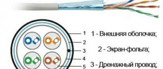
The telephone cable is pinned out using RJ-11, RJ-12, RJ-14 and RJ-25 connectors. RJ is an abbreviation for the English words Registered Jack, which literally translates as registered connector. The connector body consists of transparent or translucent plastic, with gold-plated contacts located inside. The RJ-11 interface is typically used for pinouting a “2-core” telephone cable, as it is a 6-position plug with 2 connectors.
RJ-12 is the unofficial name for the RJ-25 interface. Essentially it's the same thing. This interface is a 6-position, 6-pin plug and is used in 6-wire digital telephony. The RJ-14 interface, which has 6 positions and 4 contacts, is also intended for the same purposes. In principle, the pinout of a “2-core” telephone cable can be done with any of the listed connectors, but you need to understand that some of the contacts may not be used.
Telephone cable: color coding
The table below shows the pinout of contacts depending on the color of the cores:
Telephone cable “4 cores”: how to properly crimp the connector
You can do this yourself - the main thing is to get the right tool. As an example, consider crimping a KSPV cable. For this you will need: . brand cable of the required length; . stripping tool (cable cutting knife); . RJ-14 connectors; . crimping Tools.
Operating procedure:
1. Prepare the required connector, telephone cable of the required length and crimping tool (crimper).
2. Using a stripping tool, remove the top insulation approximately 5-7 mm.
3. Push the connector onto the cable until it stops. The color layout of the wires on both ends of the cable must match.
4. Using a crimper, crimp the connector. During the crimping process, the contact knives pierce the core insulation, thereby forming an electrical contact.
5. Remove the cable from the crimp and check the quality of the connection. If necessary, the procedure can be repeated.
Now that the cable is ready, all that remains is to test it. There are two ways: ring with a special tester for connectors or connect the cable to the telephone line and check for the presence of a signal.
is one of the leaders in the sale of cable products and has warehouses located in almost all regions of the Russian Federation. By consulting with the company’s specialists, you can purchase the brand you need at competitive prices.
To connect a landline telephone to a line, you need a working line from the PBX and the ability to connect a telephone to it. Telephones are connected to the line using telephone sockets.
There are several standards for such sockets; they are used for different purposes: connecting one or more telephones, creating leased lines. In apartments, the RJ 11 standard socket is most often used. How to connect a telephone socket of this standard yourself?
Types of equipment
With the development of technology, telephone sets are improved, but in general the principle of their operation remains unchanged. To connect them to the communication line, special sockets are still used.
In Russia, from the 80s until recently, a single standard was used - RTShK-4. Even earlier, wires were connected by simply twisting them together. Now there are several standards.
The development of microprocessor technologies has led to the replacement of RTShK-4 type sockets with others - marked RJ. With their help, you can connect up to four telephones to the line. The abbreviation RJ stands for Registered Jack. There are several standards for telephone sockets with this designation:
- RJ 9 - connector that connects the handset to a landline telephone,
- RJ 11 - it is the one most often used in residential buildings and apartments, the first standard adopted in the USA, also called the “Euro socket”, has two contacts and connects one telephone,
- RJ 14 - often used in office premises, has contacts and 4 wires, is convenient for connecting additional lines - you can connect two telephones with a separate line, in apartments it is rarely used to connect a telephone,
- RJ 25 is a model with three pairs of contacts; it is difficult to connect it yourself; it is better to entrust such work to specialists.
- RJ 45 is a device with 4 pairs of contacts, it is used to connect computer and telephone networks or connect a telephone to a line.
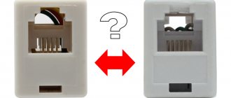
There are also combined versions of RTShK-4 and RJ 11 with both types of connectors. Such devices are used to connect computer and telephone networks. In addition, they can be used to connect devices with old and new plugs to the network.
There are also RJ 12 sockets, but they are not standard, as Legrand products are designated as RJ11 or RJ 25. TAE type devices are used to connect German and French telephone sets to the line.
How to crimp a telephone cable with 2-4 cores: complete step-by-step instructions
Hello, fellow system administrator or just a lover of computer and not so much technology. Today we will talk about crimping a telephone cable with 2 or 4 cores. I’ll say right away that they are much easier to crimp. For crimping we need the cables themselves. There are standard telephone cables of the SHTLP type, and there are KSPV-2 or KSPV-4, which are often used in alarm connections.
In order to remove the braid, we need to take a utility knife. I think it’s much more convenient for them to do it. By the way, some stores sell separate knives specifically for cleaning network and telephone cables. I remember my colleague had one - it was quite convenient and fast.
And of course, crimping tongs, or more correctly, “crimping tongs.” It is best to use a metal structure if you will be crimping frequently. The fact is that cheap plastic pliers very often fail and they begin to crimp crookedly. Because of this, the core does not fall into the center of the wire and does not pierce it. Because of this, there is no connection and you have to crimp again. Also, these pliers very often have an additional knife for cutting the braid, but most often they are not convenient and additionally cut the wires, so it is best to use a regular stationery knife.
- Scheme and crimping
- to the author of the article
Scheme and crimping
- First you need to carefully bite off the desired length of wire. From experience I will say that it is better to leave at least a meter or one and a half - for every firefighter. Next, carefully remove the braid to the length so that the base is under the connector when crimping.
- Now we insert these two wires in the center into the connector, so that there is one free wire on each side. There is no difference in the colors of the wires, so feel free to insert them as they are inserted. You also need to look from the reverse side so that both wires reach the very end. Now, holding the base of the cable and the connector itself, insert it into the pliers and press them in one fell swoop. To be sure, the procedure can be repeated;
- If crimping is done on 4 cores, then the classic “Straight-Pinned” line is most often used - it can be seen in the picture above on the right side. But some devices use the reverse “Cross-Pinned” scheme. Which one to use – this needs to be looked at in the configuration for the connected devices.
Here are a few more crimping schemes for RJ25, RJ14, RJ11 connectors:
Here the complexity increases with the number of wires. So, when pushing them into all the grooves on the connector, it often happens that the side ones simply lift up and crimping does not occur. Therefore, when you insert the wire, check a few more times to ensure that all the wires are in their place. You can push the base of the cable slightly to get them into place.
Now you know how to crimp a telephone cable and there’s really nothing complicated. The most important thing is to choose the right circuit for a particular device. For a regular telephone line and communication, connections via 2 wires are suitable. Also, if you have any questions, feel free to ask them in the comments.
Installation methods
Telephone sockets can be installed in an open or closed manner. The open method means that all the decoration on the wall is preserved; the equipment is attached directly to the wallpaper or paint.
In this case, the wires are hidden in a cable channel located in the baseboard or on the wall. You can find cable channels of different colors and sizes, baseboards with a cable channel inside. Models with snap-on lids are convenient. There are also baseboards with built-in sockets. When buying them, choose those whose front panel fits well to the base, otherwise over time it will begin to lag.
Sometimes devices are mounted not on the wall, but on the floor. When connecting in an open way, they can even be glued with double-sided tape.
If the telephone socket is connected in a closed (hidden) way, the wires are laid in the channel before the socket is installed in the socket box. Sometimes the wires are laid in the wall and the socket is installed outside. Most often they use a copper single-core cable KPSV in a white polyethylene sheath or a copper single-pair cable TRP.
Most often, telephone sockets are not installed separately, but as part of an outlet block, for example, together with an electrical outlet and a switch, as in the photo.
Advice! To disguise the structure, place them behind furniture facades or behind monitors and TVs.
Telephone socket device
A telephone socket consists of several main elements:
- housings made of dielectric (non-conducting) material - ceramics or plastic,
- contacts - spring-loaded brass parts that are needed for reliable connection of conductive parts and uninterrupted flow of current,
- terminals - adapters for connecting cables.
The contact sockets of the device are recessed into the housing. This arrangement prevents accidental short circuits.
Telephone sockets can be single or multi-socket. Single-connector models allow you to connect one telephone set, multi-connector models allow you to connect several. The RJ 11 socket is a single-socket socket; it can be used to connect only one telephone.
Telephone sockets - types and a little about their installation
Telephone sockets are included in the category of information electrical installation products. Their main purpose is to transmit data, which is why they differ from electrical outlets.
Necessary use for subscriber equipment, connection of mini-PBX, individual telephones, modems and faxes and other office equipment with the telephone network
The design of the socket depends on the presence of one or more connectors, their types and the difference in the cross-connect field.
There are several types of sockets
- RJ-11, this type of socket is marked as XP - XC demonstrates the number of positions and the number of active connected contacts.
The table shows the pinout of detachable convectors: RJ-11, RJ-12 (RJ-25), RJ-14
- RJ-11 type sockets, this marking indicates that the design uses connectors: 4p4c or 4p2c. 4p, there are 4 working contacts in the socket. If the connector is indicated as 2c and 4c, then this indicates that 2 and 4 contact blades are working. This type of connector is used to connect its handset to a telephone set.
- RJ-12 type sockets marked as 6р4с; 6р2с; 6р6с indicates that the first number indicates the number of seats, the second marked number indicates how many contact knives can be inserted into the socket. A similar connector is used in telephony for switching a telephone network line into a patch panel and for connecting the device to a telephone socket of a local network.
Rice. No. 2. The telephone network plug differs in the number of contacts involved.
For installation and correct connection of connectors, twisted cable pairs are crimped. Soldering is not used for connection. Crimping operations are performed using crimper pliers. For error-free cable connection in modern sockets, the Jung mechanism is used; the cable inserted into the device is connected by piercing without the use of additional tools and without removing the insulation which has become unnecessary. The mechanism works by turning the mounting screw ¼ turn.
Classification of telephone sockets by type of installation
There are overhead and built-in sockets, and the second type is used to maintain a presentable appearance of the interior and requires hidden installation of telephone wire.
In addition, there are sockets, distinguished by the type of configuration, which combine in their design contact sockets for connecting a telephone network and sockets for connecting a computer or modem for an Ethernet network. The security of communication and the high speed that these electrical installation products can provide, up to 100 Mbit/s, make them indispensable and in-demand devices in a modern apartment.
Installation of a telephone socket
Important: When installing telephone sockets and connecting them, you must remember that the red conductor is traditionally considered a minus, and the green conductor is a plus.
The polarity in the sockets can be checked using a multimeter; if the connection is incorrect, then you will see a minus on the display. When plugging a six-pin connector into an RC45 telephone socket with 8-pin outputs, a short circuit may occur. Without any consequences, only a 6-pin connector can be connected to a computer socket. The wire for laying a telephone line is used type TRP 2x0.4 (noodles) with a dividing strip between the conductors for safe fastening for the wire and for convenient stripping.
Currently, optical fiber is increasingly used for multi-channel communication lines. Their advantage is excellent insulation and conductivity of information. UPMK is used to secure the technological supplies of the optical cable on the supports. More details can be found here https://td.opten.spb.ru/komm/uzdelia-vnutrizonovie-MTOK?obj=100
Write comments or additions to the article, maybe I missed something. Take a look at the site map, I will be glad if you find anything else useful on my site.
elektronchic.ru
RJ 11 connection
RJ 11 has two wires, so it’s easy to connect it yourself at home. To do this, you will need to connect the two ends of the wire with certain contacts in the socket, so that in the plug and in the socket they are located in a mirror image. For installation you need:
- two-core cables with a thickness of 0.3-0.5 mm,
- screwdrivers - flat or Phillips, depending on the type of screws, with an insulated handle,
- drill,
- insulation removal tool,
- tester,
- tool for crimping contacts - you can not use it, but crimp the contact plates with a screwdriver, but then the plug will not look so neat.
The video shows how to properly connect a telephone socket to the line.
Important! Work on connecting the socket should be carried out using rubber or latex gloves. The voltage in the low-current network reaches 60 V, dropping to 12 V when the tube is removed. If they try to call the phone, a voltage of 120 V will arise in the wires, that is, they may receive an electric shock. With such tension it is not dangerous, but unpleasant.
First of all, you need to turn off the electricity. Next, you need to remove the insulation from the wires. This is done with side cutters, pliers or a regular knife. You need to carefully remove the insulation from the wires so as not to damage the core of the telephone cable itself, otherwise it may break in the future.
Do not burn the insulation and then remove it with your fingers. You can burn yourself with hot plastic, and with this method it is difficult to remove the insulation carefully. You need to strip the wires at a distance of 4 cm from the end.
It is advisable to strip the wires generously: they are thin and fragile and can be easily damaged. The excess part, if any remains, can be easily hidden under the socket body. For closed installation, for convenience, the wires are made to protrude beyond the wall surface by 5-8 cm.
Next, use a tester to check the polarity of the wires. Typically, in telephone jacks, the red wire is positive and the green wire is negative. But it is better to check the polarity, since it is not known how the wires were located before. If it is not possible to use a tester, then connect the cables according to the diagram that comes with the device.
To check if the line is working, you need a voltmeter (multimeter). The line voltage should be 40-60 V.
After this, the wires are connected to the outlet according to the diagram. To do this, you will need a screwdriver - insert the wires into the connectors and tighten the screws, clamping them well.
If you need to install the outlet in a closed way, then first markings are applied to the wall showing where the device will be located. Then, using a puncher, holes are made according to the markings and the structure is secured with self-tapping screws. A protective casing is installed on top. At the end the device is also tested.
If you are installing a new point and there is no space for sockets on the wall, then first make a recess for them - a socket box. It is drilled out using a special crown attachment on a hammer drill with a diameter of 6-7 cm. Channels for laying wires are also drilled using a hammer drill. If there is no hammer drill, this can be done with a hammer and chisel. But such work is much longer and more labor-intensive.
After this, install the device in the socket box, making sure that the cables are not intertwined. Then the socket is secured using self-tapping screws and expansion screws. The gaps between the socket box and the wall are covered with gypsum mortar.
When the solution hardens, install the protective edging and front panel. The protective edging in modern models is attached with latches, and the front panel is fixed with screws.
What is the correct wiring diagram for a telephone cable?
I think that everyone who has, or had, a landline telephone has been faced with the task of crimping a telephone cable. If a person is familiar with this matter, there is nothing complicated. If you have never encountered such a task before, it may seem simply impossible. But I really don’t want to call a specialist for such a small thing. Well, don’t worry, the task is quite real.
It is very inconvenient to work with such thin veins, especially if you do not have the appropriate tool, they tear very easily. Each core is enclosed in insulation of a certain color. Each wire must be connected to its own contact, but for this you need to know the connection diagram. There are two standard standards, they are called T568A and T568B. In Russia it is customary to use the second one - T568B. Although, I don’t see any particular contraindications to other standards, if there is such a need. However, choose only one scheme and stick to it on each section of the cable line.
You will need the following:
- telephone wire,
- crimping device (if not, you can rent it),
- RJ-45 connector
Cut the shell with a construction or stationery knife, remove it and the internal conductors will appear in front of you, straighten the wires and arrange them the way they should be located. Align them along the same line lengthwise and if they are different lengths, trim off the excess. Insert the wires into the connector all the way, making sure that each wire fits into its own groove. Compress and enjoy the work done.
You can also try to crimp the cable with a screwdriver, but this is a last resort; you can find tutorials on YouTube.
www.remotvet.ru
Connection diagrams
Telephone sockets will be connected according to certain patterns. Their wires are marked with color or numbers; there are different options, but a wiring diagram for the telephone socket is usually included with the device.
Polarity is usually not that important, but some devices may not function properly if it is not observed. The connection diagram is shown in the figure.
Twisted pair cores are also marked according to different standards, which are given in the tables. There is an old, new and German scheme.
| New marking | |||
| Contact number | Polarity | ||
| blue-white | |||
| Old scheme | |||
| Contact number | Polarity | ||
| German scheme | |||
| Contact number | Polarity | ||
| brown | |||
To properly connect your phone and get a well-functioning line, you need to take into account some recommendations.
- Most often, an internal (hidden) outlet is installed. It fits well into any interior, but it is more difficult to install, and it can also damage the decorative finish of the walls. Open type sockets are easy to maintain, install and dismantle; their installation does not damage the finish, but they do not look very aesthetically pleasing.
- Preference should be given to products from well-known manufacturers. These include the companies Legrand and Vico.
- If the socket does not come with a wire marking diagram, you can use the tables above. In the new marking, the positive wire of the RJ 11 socket is the same color as the negative wire, but with the addition of white. According to the old scheme, positive is green and negative is red. In the German version, negative is white, and positive is brown.
Preparing to connect
Before moving on to direct installation work regarding connecting Legrand brand devices, it is recommended to prepare a set of the following tools:
- A utility knife or other sharp object for stripping the insulating braid on the wires.
When installing the Legrand devices in question, the need to strip the wires was eliminated. The built-in mechanism in the products allows for self-cleaning.
- Phillips and flat head screwdriver.
- Tester for measuring network voltage.
- Latex gloves.
The voltage in telephone networks is minimal (when calling at 120V) and does not cause harm to the human body. However, it will be sensitive and unpleasant for your hands.
- Crimping Tools.
If you use even a double plug of Euro RJ11 connectors, as well as for plugs, you need a tool for crimping the contact plates. It is acceptable to ignore this requirement. The double design in the internal design, of course, will not have such an attractive appearance, but the contact plates can simply be pressed down using a flat-head screwdriver. It is worth pressing each contact sequentially.