An electrical diagram is a document in which, according to GOST rules, connections between the component parts of devices operating due to the flow of electricity are indicated. As you understand, this drawing gives electricians an understanding of how the installation works and what elements it consists of. The main purpose of the electrical diagram is to help in connecting installations, as well as troubleshooting in the circuit.
First, you need to understand what is meant by types and what is meant by types of documents. So, according to GOST 2.701-84, there are the following types of circuits (brief designation in brackets):
- Electrical (E).
- Hydraulic (G).
- Pneumatic (P).
- Gas (X).
- Kinematic (K).
- Vacuum (B).
- Optical (L).
- Energy (P).
- Divisions (E).
- Combined (C).
As for the types, the main ones are:
- Structural (1).
- Functional (2).
- Fundamental (complete) (3).
- Connections (installation) (4).
- Connections (5).
- General (6).
- Location (7).
- United (8).
Based on the indicated designations, you can understand its type and type by the name of the electrical circuit.
Next, we will consider in detail the purpose and composition of each of the listed types of electrical circuits. Before doing this, we recommend that you familiarize yourself with the standard symbols on the diagrams to make it even easier to understand what each version of the drawing is.
How to read electrical diagrams
Electrical circuits must be drawn up in accordance with GOST 2.702-75. In the circuit code, its type is indicated by the letter E (electrical). The type of circuit is indicated by numbers:
- 0 – united
- 1 – structural
- 2 – functional
- 3 – fundamental
- 4 – mounting
- 5 – connections
- 6 – general
- 7 – locations
It turns out that the code of the electrical circuit diagram should contain the designation E3.
In order to learn how to read schematic diagrams, you need to understand the designations of individual elements, and learn to imagine how the system as a whole will work. Let's consider the basic elements and principles of constructing electrical circuit diagrams .
Definition and purpose of each electrical circuit
Each type of electrical circuit is implemented in the form of a drawing or graphic image, made manually or using printed devices. The main differences are due to the description of certain functions, indication of the sequence, principle of operation, or connection to something.
GOST 2.702-2011 , as well as GOST 2.708-81, are considered quite important .
They install:
- image requirements;
- principles of component arrangement;
- preparation of drawings;
- application of designations and technical characteristics.
Next, we will consider in detail the features of each type of electrical circuit.
Fundamental (full)
A schematic diagram is intended to explain the principle of operation of a particular device. Most often it is used for various distribution devices in power circuits, any devices, etc.
Circuit diagram example
Schematic diagrams must indicate the operating electrical components and the connections between them, power contacts and electrical components connecting radio components. In turn, such electrical circuits are divided into two subtypes: single-line and complete.
Single-line circuits are also called primary circuits; they usually indicate the power part of the equipment or electrical installation. On the other hand, a single line diagram is widely used to indicate three-phase circuits, where all equipment on three phases has an identical arrangement and connection. Due to this, in the single-line version, only one phase is demonstrated with some deviations in places where the equipment in different phases is different.
In addition to power circuits, there are also low-current circuits for powering protections, measuring equipment and various electronic devices. Such secondary circuit diagrams are called complete, as they show a complete picture of the entire equipment, even highlighting the state of some contacts and parts of the equipment. Alas, due to the complexity of modern equipment, not all devices can be depicted on one sheet, so complete ones can be elemental and expanded.
Full scheme
Structural
Block diagrams provide a general image of a device, all components or individual units of which are made in the form of blocks indicating equipment, and connections between blocks can indicate certain operations connecting individual blocks with each other.
Structural scheme
This type of graphic image is intended to give a general idea of the device and principle of operation, therefore they are often marked with arrows, explanatory inscriptions and other symbols that simplify understanding of the process or explain the operation of the device. To work with such an image, you do not need to have an electrical engineering education, since its designations will be clear even to a person who is not experienced in electricity.
Functional
A functional diagram is a more detailed version of a structural diagram; on it, all elements are also depicted as separate blocks. The main difference is that each block already has an individual form of designation in accordance with its functional purpose. It is also possible to highlight different types of connections between parts, combine parts into blocks, etc.
Functional diagram
General
The general diagram is intended to depict the locations of electrical devices on the ground or within an electrical installation. Determines the main types of electrical connections of these devices, places of their implementation, etc. This type is mandatory when developing various design documents at the design stage. But in addition to the general one, the design documentation includes two more equally important diagrams - connections and connections.
General scheme
Connection diagram (installation)
The connection diagram is used to graphically depict electrical equipment connection points. It indicates a specific connection to parts of buildings, distribution systems, in relation to which the installation of electrical equipment should be carried out, due to which this type of diagram is also called installation diagram.
Most often, wiring diagrams are used to indicate the layout of electrical circuits in a building; they are widely used during repairs to indicate places for laying wiring, installing junction boxes and connecting points to devices and device contacts.
Wiring diagram
The figure above shows an example of a wiring diagram; as you can see, each option can have its own symbols, indicated separately. There are links to each specific room and planned electrical equipment, lighting fixtures, etc. In the future, it is used not only for installation work, but can also be used during operation.
Connections
A wiring diagram is used to indicate the principles of connecting various electrical or electronic components into a single system. Sometimes the units are assumed to be geographically separated, in other situations they may be located within the same switchgear, busbar or rack. An example of this is shown in the figure below:
Connection diagram
Depending on the complexity of the graphic and the number of connections displayed, it may be supplemented with connection tables to explain the pinout order and connection of the product.
Locations
It is also part of the design documentation and helps determine the locations of all parts of the electrical installation relative to each other and other significant objects.
Layout diagram
The layout diagram may include:
- components of the entire object, and, if necessary, connections between all parts;
- connecting wires, cables, cords, etc. in a simplified form;
- the name of each element, its type and the document on the basis of which it is applied.
Such an image can be performed in both two-dimensional and three-dimensional space. But in any case, the image must be scaled in relation to actual dimensions and distances.
3D layout
United
Combined scheme
The combined scheme is built on the basis of several types of images that we discussed earlier. This structure is designed to simplify the work of electricians or designers by combining various information into a single whole. But in practice, it is not always advisable to combine several types of graphic elements. This is due to the complexity of some instruments and devices, in which, due to the clutter of elements, it is quite difficult to combine different images.
Designation of communication lines on electrical diagrams
Individual elements on electrical diagrams are connected by solid lines, which can symbolize various cables, channels, buses, and wires.
The intersection of unconnected wires is depicted as follows:
A dot is placed at the junction of communication lines.
The neutral wire is designated by the letter N, and the grounding by the symbol:
Contacts
An important element of electrical circuits are switching contacts, or keys as they are called. The most common are normally open, normally closed and switching contacts ; their designations are shown in the figure.
In order to understand how the system will work when switching a contact, it is necessary to mentally move the contact element from one communication line to another.
Controls
Relays are used in many electrical drives.
When current passes through the relay winding, the contact switches; the connection between the control relay and the contact can be represented by a dotted line.
Also, the associated relay and contact may have the same letter designation.
Time relays for leading and falling edges are designated:
Reed switch - a switching contact that is triggered when exposed to a magnetic field has the following electrical circuit:
Actuators
Electric motors and electromagnets are the most common actuators in electrical systems:
Energy sources
The designation of a generator - a device that converts mechanical energy into electrical energy is shown in the figure.
Other power supplies are shown in the following picture.
Signaling devices
Signaling devices – lamps, LEDs – are often indicated on electrical diagrams. These devices are depicted as follows:
Measuring instruments
The most common designations on electrical diagrams are ammeter, voltmeter , or a general designation of a measuring device.
Common Elements
Few circuits can do without such elements as a resistor, capacitor, diode . The identification of these devices is shown in the following illustration.
The designation of thyristors and operational amplifiers is shown in the figure.
Designation of transistors on the diagram
The electrical circuit of transistors - elements of the electrical system capable of controlling the current in the output circuit when influenced by the input signal, is shown in the figure.
Logic elements
On electrical diagrams you can find two ways to designate logical elements “AND”, “OR”, “YES”, “NOT”.
Common wire designation
In complex electrical circuits, in order to improve the readability of the diagram, the conductors connected to the negative terminal of the power source are often not shown. And instead of them, signs are used indicating the negative wire, which is also called common or ground or chassis or ground.
Next to the grounding sign, especially in English-language circuits, there is often the inscription GND, short for GRAUND - ground.
However, you should know that the common wire does not have to be negative; it can also be positive. Especially often, the positive common wire was mistaken for the positive common wire in old Soviet circuits, which predominantly used transistors of p–n–p structure.
Therefore, when they say that the potential at some point in the circuit is equal to some voltage, this means that the voltage between the indicated point and the “minus” of the power supply is equal to the corresponding value.
For example, if the voltage at point 1 is 8 V, and at point 2 it is 4 V, then you need to install the positive probe of the voltmeter at the corresponding point, and the negative probe to the common wire or negative terminal.
This approach is quite often used, since it is very convenient from a practical point of view, since it is enough to indicate only one point.
This is especially often used when setting up or adjusting radio-electronic equipment. Therefore, learning to read electrical circuits is much easier by using potentials at specific points.
How to read an electrical diagram
- Conduct a general familiarization with the electrical circuit, read all notes and technical requirements.
- Compare the designations of the elements on the electrical diagram with the list of elements.
- Find power sources on the diagram and determine the type of current.
- Find electric motors on the electrical diagram and determine their power supply system.
- Identify electrical system protection devices - fuses, circuit breakers, etc., and identify the area of their operation.
- Highlight control elements on the electrical circuit diagram, determine which circuits are activated, or disabled, and switched when switching each control node.
- Analyze the operation of each electrical circuit of the electrical circuit, identify the main and auxiliary devices on it, determine the conditions of their operation, and, if necessary, familiarize yourself with the technical documentation for electrical devices.
- Based on the analysis of the operation of individual electrical circuits, draw conclusions about the operation of the electrical system as a whole.
We looked at the basic designations of electric drive elements, knowing which you can learn to read some electrical diagrams. Of course, to understand the operation of complex electrical systems using circuit diagrams, you will have to study other notations. You can tell us what symbols you would like to see in the comments to the article.
Source: www.hydro-pnevmo.ru
Creating a drawing using specialized programs
The development of computer technology has greatly simplified the process of creating OSE. For these purposes, programs have been developed that allow you to complete a project in the shortest possible time in accordance with all state standards on a computer. Next, we will consider the most common options.
1 2 3 scheme
Belongs to the category of free software. Typically used by students and novice users. The program is Russified and available for download on the official website. With its help, you can select the series and size of the planned electrical panel housing, as well as designate each individual machine. The program is designed to create single-line apartment diagrams. To control functions, you only need to use the mouse.
Free program 1-2-3 scheme
XL Pro² by Legrand
Designed for designing electrical circuits using elements that are designed for low voltage. The following techniques can be used for the layout and placement of XL³ series enclosures and enclosures:
- Select electrical components from Legrand from the list prepared by the program.
- By forming a single-line diagram.
Design and calculation program for creating electrical cabinet diagrams XL PRO 2
The software is also free, but pre-registration is required. XL Pro² is able to automatically determine and place on the diagram the required type of distribution complex, and also indicate the cost of the equipment.
XL PRO³
Provides the possibility of using electrical circuit design techniques similar to the XL Pro² program. OSE can be assembled with elements from Legrand, which are designed for currents up to 6.3 kA. At the same time, there is a function for automatically adjusting the location of electrical equipment, selecting distribution panels with an indication of their cost. You can download XL PRO³ on the official website.
Legrand XL Pro³ visualization module
Rapsodie - distribution board layout
The program in question carries out the quick layout of low-voltage distribution cabinets from Schneider-Electric. In addition to the main elements, various additional accessories can be added to the circuit, with the possibility of adding missing types of electrical equipment. In this case, there is a function for automatically adjusting the configuration of previously selected elements of a single-line diagram. Ultimately, you can visualize the developed project, as well as display its cost, taking into account the costs of installation work.
Rapsodie comes in Russian with an accessible and understandable interface, with the ability to export or print the result. To use the product, you will need to first submit an application on the official website. After approval, the user completes a training course.
Schneider Electric Rapsodie program
To correctly draw the OSE, you will need to comply with established norms and rules. To do this, you need to study the relevant technical documentation. The use of current drawing programs helps to significantly speed up the process of creating a drawing.
Techniques for reading electrical diagrams
Reading a schematic diagram begins with determining the purpose of the device, the composition of its circuit (power part, control unit, protection, etc.) and familiarizing yourself with the list of elements, for which you find each of them on the diagram, read all the notes and explanations.
Then the power supply system is determined, both for the device as a whole and for its component parts: electric motors, windings of magnetic starters, relays, electromagnets, complex devices, regulators of individual elements, etc. To do this, find all power sources on the diagram (type of current, rated voltage, phasing in AC circuits and polarity in DC circuits, etc.). The diagram identifies general switching devices, as well as protection devices: circuit breakers, fuses, maximum current and minimum voltage relays, etc. The settings of the devices are determined from the inscriptions on the diagram, tables or notes and, finally, the protection zone of each of them is assessed.
They study all possible circuits of each electrical receiver (electric motor, magnetic starter windings, relays, devices, etc.).
Thus, the conditions of occurrence, possible errors and causes of failure are identified.
From these starting points, you need to read and analyze electrical circuit diagrams.
In general, this analysis requires deep knowledge (electrical engineering, electronics, automation and other special electrical disciplines), knowledge of the methodology for developing, drawing up and reading circuits.
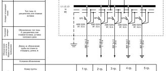
As an example, let us consider the composition and principle of occurrence of the following schematic diagram of electric drive control (Fig. 4), i.e. Let's read it. (See Fig. 1.5.)
Figure 1.5. Schematic diagram of electric drive control
The electrical circuit consists of a power section and a control circuit. The power part is an electric drive of a mechanism (installation), consisting of a three-phase asynchronous electric motor M, the stator windings of which are connected through the main (power) contacts of the KMZ magnetic starter KM and the main contacts of the QF circuit breaker to the three-phase network A, B, C, N (380/ 220V). The engine is protected by thermal relays KK1 and KK2.
The control circuit is powered by three-phase voltage A,B,C,N. The control circuit is protected by fuse FU. To make it easier to read, the control circuit variables on the left are numbered (1-6) and annotated with a functional table on the right.
Operating principle (working algorithm):
When you briefly press the SB 1 “Start” button (provided that the thermal relay KK1, KK2 are in the initial state, i.e. the contacts are closed and the block contact of the peripheral device is also closed), current will flow through the protection circuit 1 in the winding of the magnetic starter KM - it is triggered and the SB 1 button is blocked by the KM4 contacts, i.e. The starter power circuit remains turned off after releasing the SB 1 button. In this case, the KM 1 contact block will also close - the EL-I “engine on” signal lamp will light up and the KM 2 contact block will open - the EL 2 “engine on” lamp will turn off.
Power supply designation
Any radio-electronic device is capable of performing its functions only in the presence of electricity. There are fundamentally two types of electricity sources: direct and alternating current. This article deals exclusively with DC sources. These include batteries or galvanic cells, rechargeable batteries, various types of power supplies, etc.
There are thousands of thousands of different batteries, galvanic cells, etc. in the world, which differ in both appearance and design. However, they are all united by a common functional purpose - to supply electronic equipment with direct current. Therefore, in the drawings of electrical circuits, sources are designated uniformly, but still with some minor differences.
It is customary to draw electrical circuits from left to right, that is, the same way as writing text. However, this rule is not always followed, especially by radio amateurs. But, nevertheless, this rule should be adopted and applied in the future.
A galvanic cell or one battery, no matter “finger”, “pinky” or tablet type, is designated as follows: two parallel lines of different lengths. A longer dash indicates the positive pole – plus “+”, and a shorter one – minus “-”.
Also, for greater clarity, battery polarity signs may be indicated. The galvanic cell or battery has a standard letter designation G.
However, radio amateurs do not always adhere to this encryption and often write the letter E instead of G, which indicates that this galvanic element is a source of electromotive force (EMF). The EMF value may also be indicated next to it, for example 1.5 V.
Sometimes, instead of a picture of the power supply, only its terminals are shown.
A group of voltaic cells that can be recharged repeatedly by a battery. In the drawings of electrical circuits they are designated similarly. Only between the parallel lines is a dotted line and the letter designation GB is used. The second letter just means “battery”.
Types of circuit diagrams
Models of electrical devices, apparatus, equipment, made using digital and alphabetic symbols, as well as graphic images, designed to understand the principles of operation of electrical circuits and the physical processes occurring in them are called schematic diagrams.
Unlike mounting ones, they do not contain data on the location of parts on printed circuit boards. The purpose of this type of drawing is to show the connections of elements with each other, indicate their type and important parameters for reading the diagram. If necessary, graphic materials are supplemented with tables, text footnotes, and diagrams.
Technical documentation of this kind is divided into 2 types:
- Staggered (multilinear) - different circuits are depicted in lines (indicated by Arabic numerals), and in each line all the elements of one circuit are arranged sequentially. This method is suitable for complex electrical and automation devices containing a large number of relays and contact groups in three-phase systems.
- Combined (single-line) - a more visual form of graphical representation of electrical connections between circuit elements. In them, in one drawing, primary circuits with connection diagrams together with control devices for switches, automation, and relay protection can be indicated. Such schemes become less popular as designs become more complex.
Single-line design diagram
Designing a design diagram is necessary when the object (be it a house, cottage or other premises) has not yet been in operation. Accordingly, this means that it does not have any electrical installation (there was no power supply at all).
In this case, the first stage in the design of a single-line design diagram is the need to carry out the entire complex of computational activities. And based on the data received, continue its preparation in terms of design work for the installation of the electrical network itself. All calculations are based on the expected loads that will occur during operation of the electrical network. Accordingly, the characteristics of the selection of all elements of the electrical network (conductors and their components), as well as automatic machines, are determined. Each of the above network components must withstand the loads designed for it.
When designing a single-line diagram, electrical energy is distributed from the switchboard through an electrical network, which is the same for all consumers of electrical energy. Since in the modern world many more high-power household electrical appliances are used compared to Soviet times, the need to install, in addition to circuit breakers, also a residual current device, which is also selected based on the above typical calculations, comes to the fore.
How does this scheme work?
The symbols of the circuit participants are located in the direction of current (signal) movement - from left to right. The specialist must have prior knowledge of the purpose and operation of the electronic and electrical parts and devices indicated in the diagram.
Groups of interconnected elements are combined into devices that solve different problems:
- power supplies, rectifiers;
- stabilizers and voltage dividers;
- amplifiers of different classes;
- multivibrators, flip-flops, blocking oscillators.
With experience, a person gains the ability to quickly read an electrical circuit, “see” the currents flowing along the circuits, the distribution of potentials, the shape, duration and amplitude of signals. By taking measurements in the right places in the circuit, the technician can judge the serviceability of the device components.
Ratings of radio components
In general, there are disagreements in this regard. According to GOST at the moment, the nominal values of parts are not indicated on circuit diagrams. This is done in order not to clutter the diagram with information.
The circuit diagram is accompanied by a list of parts, wiring and structural diagrams, as well as a printed circuit board.
There is another generally accepted standard. The diagrams indicate the ratings of some parts and their operating voltages.
For example, in this circuit there are two resistors.
By default, resistance without a prefix is written only as a number. R2 has a resistance of 220 Ohms. And R3 has a letter after the number. The resistance of this resistor reads 2.2k ohms (2,200 ohms).
Consider two capacitors in the diagram.
In this case, C5 is a non-polar capacitor with a capacitance of 0.01 µF. Microfarads can be designated either uF or uF. And capacitor C6 is polar and electrolytic. This is indicated by the plus sign near the UGO. Capacitance C6 is 470 μF. The rated operating voltage is indicated in volts. Here for C6 it is 16 V.
Nanofarads are denoted as nF.
If there is no microfarad (uF) or nanofarad (nF) prefix on the circuit, then the capacitance of this capacitor is measured in picofarads (pF, pF). This condition is not common, so carefully study the diagram you are about to read or assemble. There are few capacitances in farads (F), so µF, nF and pF are used.
Designations used according to GOST
GOST regulates the following types of designations:
- amendments and inscriptions, rules for the execution of electrical circuits, completeness and types of documents (indicated in the ESKD (Unified System of Design Documentation 2006-2013);
- general requirements for the implementation of schemes, their types and types (GOST 2.701-2008).
The documents define UGO - a conventional graphic designation of individual parts, lines of their interconnection, functional groups and devices. Most imaging is done using software that can be downloaded from the web. You can use online versions of constructors developed taking into account the requirements of the standards. If necessary, it is allowed to use non-standardized UGOs.
On the drawings (near or inside the UGO, in a gap or at the ends of interconnection lines, in free fields) there is text data, the nature of which is determined by the purpose of the circuit diagrams.
Why is the E4 connection diagram needed?
According to their purpose, drawings can be divided into:
- structural;
- functional;
- principled;
- installation;
- are common.
Electrical connection diagram E4 example
Each of them has a code from 0 to 7.
One of the above diagrams will help determine the design of the product itself. The drawing can indicate all the elements and devices located in the structure, their fasteners, types of connections, etc. With the help of such drawings, you can easily and correctly connect devices to the network.
All devices and components are shown in the form of rectangles or outlines of figures, lines, and ESKD standards are also applied. Near the outlines, lines and elements there may be conventional graphic symbols and numbers. Recently, when making plans, only GOST standards of the new type from 2012 are used.
The connection for E6 and E6 is described in detail below.
Rules for reading diagrams and working on them
In order to quickly and correctly read electrical diagrams, you need:
- Know the symbolic graphic designations of elements: capacitors, resistors, inductors, relays, motors, switches, batteries, lamps and others.
- Be able to mentally separate complex circuits into simple ones, and use additional structural and functional types of circuits. You should study the drawings systematically, in accordance with the logic of the device. If documents contain links to other sources, you should familiarize yourself with them.
- Studying the operation of the circuit may require constructing diagrams of the interaction of individual sections of the circuit, reflecting the order of operation of telemetry, automation, and protection.
Content
Installation and technological diagram of a heated floor 1 - ball-type valve installed on the supply line; 2 — ball valve, at the outlet; 3 - cleaning filter; 4 — valve to the return line; 5 - three-way mixing shut-off valve; 6 - restart valve; 7 - pump that circulates the working fluid; 8 - valve that shuts off the return manifold; 9 - shut-off valves blocking the entrance to the supply manifold; 10 — return manifold body; 12 - ball-type shut-off valves, blocking the return; 13 - valves for shutting off the supply; 14 — valve for bleeding air; 15 — drainage shut-off valves; 16 - central heating battery. They helped a lot, they also explained a lot, now I’m trying to figure it out myself, but sometimes I still turn to this company for advice.
Since the elements of the circuit are usually depicted in a spaced manner, for example, the contactor coil is in one place, and its contacts in another, it is necessary that all its parts of the coil, the main and auxiliary contacts, have the same reference designation assigned to this element, namely : if the contactor coil is designated KM2 KM is the general designation of the coils of electromagnetic contactors, 2 is the serial number of the contactor in the electric drive circuit, then the contacts of this contactor are designated as KM2. Clarity of operation of the circuit in emergency conditions. Their actual location is not taken into account.
Purpose Let's start with the basics.
When developing technological process automation systems, circuit diagrams of independent elements, installations or sections of the automated system are usually drawn up, for example, a valve control circuit, an automatic and remote pump control circuit, a tank level signaling circuit, etc. In turn, the circuit diagram can have two varieties : single line or full. For example, for a terminal block consisting of 10 terminals, each of them can be assigned a unique address in the wiring diagram.
More often, power wires are used for supply circuits and on cambrics, as a rule, only the phase is indicated. Over time, you yourself will know where, what should be. In turn, the circuit diagram can have two varieties: single-line or complete. Communication lines should consist of horizontal and vertical segments and have the least number of kinks and mutual intersections.
General classification
Rate this article. If, when rotating or mirroring conventional graphic symbols, the meaning may be disrupted or the readability of the symbols may deteriorate, then such symbols are depicted only in the position in which they are given in the relevant standards. It provides full disclosure of the operation of electrical equipment. You need to know how to read and assemble a diagram. An example of an explanatory flow diagram is shown in Fig.
There are no standards for depicting the graphic symbols of these diagrams. Then this pigtail is carefully assembled and laid along the body along the cabinet wall, the wires are laid to the element where they should go according to the wiring diagram, that is, from one element to another. First, let's determine the operating procedure of the chandelier. When a common line approaches the elements, each communication line is again depicted as a separate line.
In general, my responsibilities only included installation of the circuit, and the configuration was already carried out by another specialist. Typically, the main circuits include the armature winding circuits of DC motors, the stator windings of asynchronous motors, etc. This type of circuit diagram gives a general idea of the operation of the electrical installation. The scheme is used for the direct production of work or for the manufacture of a product. The middle conductor is designated by the letter M. How to read electrical diagrams
Known circuit diagrams
It is better to consolidate reading skills on well-described diagrams, which have already become classic. They contain a small number of integral elements.
Radio receiver “Ishim-003”
The device has been produced since 1984. It is a receiver of frequency and amplitude modulated radio waves in the short, medium and long ranges. Widespread among radio amateurs.
It is made according to a superheterodyne circuit with two channels (FM and AM) and a frequency converter.
The frequency-modulated channel is made of an RF amplifier, a converter, an amplifier and a frequency detector. An amplitude modulated channel consists of a UHF, an IF, an IF and an amplitude detector.
At low frequencies, amplification is produced by the general ULF. The design includes an electronic counting scale, a setting indicator and a power supply.
Vega-108 stereo
The device appeared in 1979 and is a stereophonic electric record player with an output power of 2*10 W and a sound frequency of 63-18000 Hz. The device not only works as an amplifier for external signals, but can also record to a tape recorder.
The schematic diagram of the electrophone consists of blocks:
- switching;
- regulators;
- nutrition;
- preamp;
- power amplifier module;
- speaker system.
The main part of the elemental base of the player were transistors: KT815V, KT814V, KT315G. The device's power supply includes a step-down transformer with 5 secondary windings, 2 diode bridges and a voltage stabilizer made on a KT315V transistor.
The G-602 device is used as a pickup head. The preamplifier consists of 2 channels using transistors KT3102D, KT361E, KT315B. A switch is made of switches and electronic circuitry.
Variable resistors are used as control elements in the regulator. With their help, the values of sound volume, balance, and timbre are set.
Almag-01
The Almag-01 medical device is intended for the treatment of skin diseases, gastrointestinal tract, and ENT organs. It affects the body with a pulsed electromagnetic field.
The device diagram includes:
- power cord;
- inductor coils (emitters);
- cable for connecting the emitter strip to the control unit;
- uninterruptible power supply;
- pulse current generator;
- Control block.
The health of the circuit is indicated by a green indicator. Yellow color indicates that pulses are being emitted. A magnetic therapy session lasts 22 minutes, after which the device automatically turns off.
Multimeter DT-832
A universal device for measuring various electrical quantities (voltage, resistance, current, etc.). The basis of the measuring device is the ICL1706 ADC microcontroller or its analogues.
Car diagram - Catalog of electronic car circuits
With the unstoppable development of the automotive industry, the design of each specific model is becoming more complex. An increasing number of tasks are assigned to electronic circuits, which means the number of monitoring sensors is growing.
Our directory contains electrical circuit diagrams for almost all popular models of domestic and foreign automakers. Here you can find circuit diagrams of domestic (VAZ, GAZ, UAZ, IZH, Moskvich), Korean (Kia, Hyundai, Daewoo, Sang Yong), German (Audi, BMW, Volkswagen, Mercedes, Opel), Japanese (Honda, Lexus, Mitsubishi , Subaru, Suzuki, Toyota, Nissan, Mazda), American (Ford, Chevrolet), French (Renault, Citroen, Peugeot), Italian (Alfa Romeo, Fiat), Swedish (Volvo, Saab), Czech (Skoda) and other automakers .
Most of the diagrams presented in the directory are color, in good quality and in Russian. This allows you to work with them more conveniently when searching for various elements, modules and nodes. To increase the size of the diagram, click on the image and then on the icon above the diagram. All electrical circuits are collected from open sources and any circuit from the site can be downloaded absolutely free. Our directory of schemes is periodically updated, so if you do not find the information you need on the site today, try to come back later.
Separately, the website contains a section for maintenance and repair of electrical equipment of various car models, and provides tips on testing electrical wiring, quickly checking and replacing fuses and lighting devices. The directory also contains a section of articles where you can find reviews and tips to help motorists on operating their cars, preparing them for winter, and much more.
If a failure or malfunction occurs, the owner of the car immediately receives an alert from the electronic system in the form of an alarm indicator that lights up.
There is probably not a single driver who has not seen such an “alarm signal” at least once. But what exactly does the error message mean? What kind of troubles await you and how soon - a trivial repair that can be postponed, or an emergency replacement of a critical element?
Most often, simple peripheral units fail: fuses, light bulbs, various lights and relays. Therefore, in order not to spend money on service stations, you can easily deal with these minor problems yourself with minimal knowledge in auto electrics.
To do this you will need several devices:
- ammeter,
- voltmeter,
- resistance meter (for testing wiring)
To simplify the task, we recommend purchasing such a universal device as an autotester (digital).
There are emergency situations when you cannot figure out the problem yourself - unless you are a diagnostic specialist or a car service employee. In this case, it is recommended to turn to professional computer diagnostics of the car - this will help you instantly identify the cause of the warning indication. You will know for sure whether your car will last another hundred kilometers - or whether you need to urgently find a repairman.
Diagnostics will allow the car owner:
- Find out if there are any hidden or unobvious defects.
- Identify errors in the functioning of components and assemblies.
- Predict possible failure or failure of one or another element.
- Set up economical fuel consumption.
A car inspection is like a medical examination for a person. Applying once a year for computer diagnostics is comparable to annual preventive tests at the clinic. It will help you catch the disease in time, saving you from worry and unnecessary costs. You could even say that this procedure is a budget option for car maintenance. Its cost will certainly pay off - due to the fact that you will avoid expensive repairs.
For prevention, to avoid serious problems with electrical equipment, the following is recommended every 15,000 kilometers:
- clean the battery from dirt and dust
- to remove electrolyte, wipe the surface of the battery with a cloth soaked in a 10% solution of ammonia or soda ash
- then wipe the battery with a dry cloth
- check the electrolyte level in the battery and, if necessary, add distilled water
- Check the battery voltage and recharge it if necessary.
Scanners: myth or reality?
Many online stores for car enthusiasts vying with each other to offer the purchase of “miraculous” scanners that supposedly allow you to perform full-fledged computer diagnostics with your own hands. The models of these devices (mostly Chinese-made equipment) are different, but the advertising for each of them promises magic. But we still advise you to refrain from purchasing such devices. A scanner that is truly effective will still only be able to be handled by a specialist, and their price is quite high. And a cheap device, as a rule, turns out to be a one-time use device.
Where to start reading diagrams?
In order to learn how to read circuits, first of all, we must study what a particular radio element looks like in a circuit. In principle, there is nothing complicated about this. The whole point is that if the Russian alphabet has 33 letters, then in order to learn the symbols of radio elements, you will have to try hard.
Until now, the whole world cannot agree on how to designate this or that radio element or device. Therefore, keep this in mind when you collect bourgeois schemes. In our article we will consider our Russian GOST version of the designation of radioelements
External connection E5
In the drawing, it is necessary first of all to indicate the product itself, its input and output components (couplings, clamps, etc.) and the contacts of cords and external installation cables connected to them, near which information about the connection itself is located.
The constituent parts of the plan are shown as quadrangles, and the input and output parts are shown as lines, segments and dotted lines. It is allowed to use simpler notation to construct the diagram.
How the harness connection is clearly indicated
Note! Connectors, clamps and other components are positioned in the same way as they appear on the product itself.
Introductory details can be placed in the form of iconic graphic symbols. The drawing must indicate the input, output or output parts that are present on the product. If these components are not included, then conventional symbols are used in the diagram.
It is allowed to write an explanation and name next to all components. As well as the necessary data from the documentation on the product. Cable products and cords are shown as separate lines. It is allowed to use markings for cable products, but its explanation is written strictly in the margins (name, cross-sectional area, power, number of cores inside).
You might be interested in Energomera tse6803vm
E6 GOST
Studying a simple circuit
Okay, let's get to the point. Let's look at a simple electrical circuit of a power supply, which used to appear in any Soviet paper publication:
If this is not the first day you have held a soldering iron in your hands, then everything will immediately become clear to you at first glance. But among my readers there are also those who are encountering such drawings for the first time. Therefore, this article is mainly for them.
Well, let's analyze it.
Basically, all diagrams are read from left to right, just like you read a book. Any different circuit can be represented as a separate block to which we supply something and from which we remove something. Here we have a circuit of a power supply to which we supply 220 Volts from the outlet of your house, and a constant voltage comes out of our unit. That is, you must understand what main function your circuit performs . You can read this in the description for it.
Single line actuator
As for the executive single-line diagram, it is designed when the facility already has an electrical supply, that is, the electrical network is in operation. To draw up such a diagram, first of all, a survey of the entire existing electrical network is carried out. After which, as in the design scheme, computational work is carried out, but ready-made information from the power supply project is taken as a basis, which is subsequently simply either modernized (if there is a need to improve the electrical network) or changed completely (if the operation of the electrical network failures and malfunctions occur).
In the end, you need to supplement the material on designing single-line diagrams with information about certain necessary documentation that you need to rely on when carrying out such work. The fundamental documents include: PUE (Electrical Installation Rules); GOST 50571.1 “Electrical installations of premises”; GOST 23274 “Buildings. Electrical installations. General technical characteristics" and other such regulatory documents.
Below you can use the online calculator to calculate the cost of designing power supply networks:
How are radioelements connected in a circuit?
So, it seems that we have decided on the task of this scheme. Straight lines are wires or printed conductors through which electric current will flow. Their task is to connect radioelements.
The point where three or more conductors connect is called a node . We can say that this is where the wiring is soldered:
If you look closely at the diagram, you can see the intersection of two conductors
Such intersection will often appear in diagrams. Remember once and for all: in this place the wires are not connected and they must be isolated from each other . In modern circuits, you can most often see this option, which already visually shows that there is no connection between them:
Here, it is as if one wire goes around the other from above, and they do not contact each other in any way.
If there was a connection between them, then we would see this picture:
Designation of wires and their connections on diagrams
Electrical wires perform the function of combining all electronic elements into a single circuit. They act as a “pipeline” - they supply electronic components with electrons. Wires are characterized by many parameters: cross-section, material, insulation, etc. We will deal with installation flexible wires.
On printed circuit boards, conductive paths serve as wires. Regardless of the type of conductor (wire or track), in the drawings of electrical circuits they are designated in the same way - a straight line.
For example, in order to light an incandescent lamp, it is necessary to supply voltage from the battery using connecting wires to the light bulb. Then the circuit will be closed and a current will begin to flow in it, which will cause the filament of the incandescent lamp to heat up until it glows.
The conductor should be denoted by a straight line: horizontal or vertical. According to the standard, wires or live paths can be depicted at an angle of 90 or 135 degrees.
In branched circuits, conductors often intersect. If an electrical connection is not formed, then a dot is not placed at the intersection.
If an electrical connection is formed at the intersection of conductors, then this place is designated by a point called an electrical node. Several conductors can intersect at the same time in a node. Here I advise you to get acquainted with Kirchhoff's first law.
What is an electrical circuit
This is a graphic image that shows all the electronic elements connected to each other by conductors. Therefore, knowledge of electrical circuits is the key to a properly assembled electronic device. This means that the main task of the assembler is to know how electronic components are indicated on the diagram, what graphic icons and additional alphabetic or numerical values.
All basic electrical circuits consist of electronic elements that have a conventional graphic designation, in short RCD. As an example, we will give a few of the simplest elements, which in graphic design are very similar to the original. This is how a resistor is designated:
Resistor
As you can see, it is very similar to the original. And this is how the speaker is designated:
Speaker
Same great similarity. That is, there are some positions that can be immediately recognized. And it's very convenient. But there are also completely different positions that either need to be remembered, or you need to know their designs in order to easily identify them on a circuit diagram. For example, the capacitor in the figure below.
Capacitor
Anyone who has long been versed in electrical engineering knows that a capacitor is two plates with a dielectric placed between them. Therefore, this icon was chosen in the graphic image; it exactly repeats the design of the element itself.
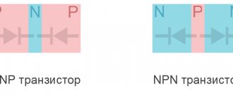
The most complex icons are for semiconductor elements. Let's look at a transistor. It should be noted that this device has three outputs: emitter, base and collector. But that's not all. Bipolar transistors have two structures: “n – p – n” and “p – n – p”. Therefore, in the diagram they are designated differently:
Transistor
As you can see, the transistor in its image does not look like it. Although, if you know the structure of the element itself, you can figure out that this is exactly what it is.
Simple diagrams for beginners, knowing a few icons, can be read without problems. But practice shows that simple electrical circuits in modern electronic devices are almost impossible to do. So you will have to learn everything related to circuit diagrams. This means that you need to understand not only the icons, but also the alphabetic and numerical designations.
What do letters and numbers mean?
All numbers and letters on the diagrams are additional information, this again comes to the question of how to read electrical diagrams correctly? Let's start with letters. A Latin letter is always written next to each RCD. Essentially, this is the letter designation of the element.
This was done specifically so that when describing the circuit or device of an electronic device, its parts could be identified. That is, do not write that it is a resistor or capacitor, but put a symbol. It's both simpler and more convenient.
Now the digital designation. It is clear that in any electronic circuit there will always be elements of the same value, that is, of the same type. Therefore, each such detail is numbered. And all this digital numbering goes from the upper left corner of the diagram, then down, then up and down again.
Attention! Experts call this numbering the “AND” rule. If you pay attention, this is how the movement according to the pattern occurs.
And one last thing. All electronic elements have certain parameters. They are usually also written next to the icon or placed in a separate table. For example, next to the capacitor, its rated capacity in micro- or picofarads, as well as its rated voltage (if such a need arises), may be indicated.
In general, everything related to semiconductor parts must be supplemented with information. This not only makes the diagram easier to read, but also allows you to avoid making mistakes when choosing the element itself during the assembly process.
Sometimes there are no digital symbols on electrical circuits. What does it mean? For example, take a resistor. This suggests that in this electrical circuit, its power indicator does not matter. That is, you can install even the most low-power option that will withstand the load of the circuit, because a low current flows in it.
And a few more notations. Conductors are graphically indicated by a straight continuous line, soldering points by a dot. But keep in mind that the dot is placed only in the place where three or more conductors are connected.
Procedure for developing OSE
When creating a single-line electrical network project, you will need to comply with certain regulatory rules. In this case, the selection of individual circuit elements must be carried out in accordance with the PUE.
What information should the OSE carry?
The diagram intended to formulate a power supply project will definitely need to reflect:
- connection point to the power source;
- type of input device (automatic machine or distribution point) indicating the rated current;
- information about the meters used to account for electricity;
- brand, length, cross-section and number of current-carrying cores of cable lines;
- calculated voltage losses and load;
- the protective devices used;
- location of internal and external lighting networks.
Development stages
Before starting to develop a single-line electrical network project, you will need to obtain technical specifications. To do this, you will need to contact the municipal electrical network department. The technical condition determines the location of the facility’s connection to the power supply network, as well as the distribution boundaries of the future power supply project.
After this, you will need to visit the department of architecture and urban planning at your place of residence. In it, make a request for the issuance of a master plan for the land plot. This is necessary to accurately determine the location of the supply line from the connection point, excluding intersections with other engineering structures. You can also determine the length of the future cable line.
Procedure for connecting to electrical networks
At the next stage, the planned loads are calculated, with all the required elements displayed on a single-line diagram. At the final stage, all that remains is to approve the project and obtain permission to connect to the power supply network.
GOST requirements and design nuances
The construction of OSE is carried out in accordance with the requirements of GOST ESKD. For this, the following GOST numbers are used:
- 709-89 - current-carrying conductors, electrical equipment and contact connections;
- 710-81 — application of alphanumeric designations;
- 721-74 - elements of general use;
- 732-68 - designation of light sources;
- 755-87 - switching devices and contact connections;
- 702-2011 - rules for designing diagrams.
Alphanumeric designations in diagrams in accordance with GOST 2.710-81
When preparing a drawing, it is recommended to adhere to the following rules:
- Initially, a frame and a stamp of the established shape are drawn.
- If necessary, you can spread the drawing onto several sheets to make it easier to read. In this case, a list with continuous numbering is formed.
- The marking of circuit elements is carried out from the power source to the end consumer. For this purpose, capital Latin letters and Arabic numerals are used. The former indicate the phase of the alternating current, and the latter indicate the sequence of the circuit.
- Odd numbers are used to indicate positive polarity, and even numbers are used for negative polarity.
- Decoding the markings of the circuit components is performed on the left side of the drawing or directly above each element.
- The main parameters of the supply network, as well as consumers, can be included in a separate table. However, its size is not regulated.
- It is allowed to use free sections of the OSE to display the technical characteristics of cable lines in the form of text.
Symbolic graphic display of circuit components
To compile the OSE you will need to use certain conventions. Most of them are reflected by GOST ESKD 2.721-74, 2.709-89, 2.755-87 and 2.732-68 in separate tables.
Project verification and approval
After the development of the OSE is completed, the signature of the direct executor is placed on it. In the future, you will need to obtain approval of the project from a responsible specialist on the part of the supplier, who will verify the provided data.
The final stage will be obtaining permission to implement the project from the head of municipal electrical networks. Depending on the established staff of the specified organization, the checking and approving specialist may combine responsibilities.