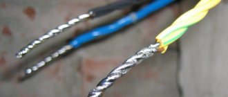
Terminating a fiber optic cable is a complex and responsible process. The reliability and durability of the further operation of the fiber-optic line depends on the quality of its implementation. In this material you will find a detailed overview of all existing methods for installing optical connectors, learn how to properly install the ends of an optical cable, and also receive a large convenient table that will help you decide which method of installing optical connectors is ideal for your case.
FOCL welding technology
The length of the optical fiber is measured, it is produced in coils. Multi-kilometer long fiber-optic transmission lines are created by two types of connections:
- detachable;
- one-piece.
Detachable ones require additional costs; connectors and adapters significantly reduce the light transmission of the signal. More often, permanent connections are made by welding fibers with special devices.
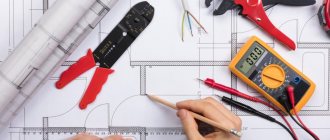
Necessary tool
High-quality installation of fiber-optic lines is impossible without two devices:
- cleaver, an apparatus for optical fiber, allows you to cut the cleaned cable strictly at a right angle;
- reflectometer or tester, it determines the accuracy of the connection.
Tools are needed to strip the insulating sheath. A standard soldering kit will do the job. There is everything there: wire cutters, pliers, solvent or alcohol, special thick wipes for removing the waterproof layer. The reliability of the connection depends on the quality of surface cleaning.
Fiber optic cable tool
Preparatory work
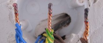
The process of preparing the cable before refilling takes a lot of time. First, the optics are examined. Water destroys the light-conducting layer. If the end of the wire is wet, cut off at least a meter from it with a wire cutter. To remove the sheath, the cable is stripped down to a hydrophobic gel. Cutting with a stripper knife does not take much time: after a circular cut at a distance of at least 3 cm from the end, it is enough to pull the cable together. The waterproof layer is removed with a solvent and lint-free wipes. It is necessary to remove the insulation completely, this affects the quality of the chip.
Connection process
The cleaver produces a high-precision perpendicular cut. After this, the welding process begins. Main stages of work:
- the ends of the wire are placed in the device towards each other and fixed;
- the device adjusts the conductor and brings the ends together;
- then an electric discharge is passed through, dust particles are destroyed in the arc zone;
- the fibers are soldered together under the action of an arc, the silicon melts, and a diffuse connection is formed;
- after welding, the connection is tested: the device moves the soldered ends apart with a certain force;
- A heat-shrinkable tube is placed over the connection; in the oven, it forms a protective sheath on the wire;
- When the device completes the second part of the work, the timer gives a sound or light signal.
Comparative table of advantages and disadvantages of optical connector installation technologies
So, let’s highlight the advantages and disadvantages of the technologies for installing optical connectors described above.
Comparative table of advantages and disadvantages of using various methods of installing optical connectors:
| Splice On Connector | Fast Connector | Pigtails | Adhesive connector | |
| Simplicity of installation technology | + | + | + | — |
| Installation speed | +/- | + | +/- | — |
| Maintaining acceptable insertion loss on the connection over a long period of time | + | — | + | + |
| Maintaining an acceptable level of signal reflection over a long period of time | + | — | + | + |
| Resistance to mechanical loads | + | +/- | +/- | +/- |
| Possibility of multiple installations | — | + | + | — |
| Convenient cable termination at the operator cross-connect | + | + | + | + |
| Convenient cable termination in outdoor distribution boxes | + | + | — | — |
| Convenient cable termination at the subscriber's premises | + | + | — | — |
| Price (cost of connectors and installation equipment) | — | +/- | +/- | + |
Cleaver and reflectometer
A cleaver is a high-precision mechanical device that provides a perpendicular cut of an optical fiber. The quality of the weld depends on the quality of the chip.
If the cleavage is bad, smart welding machines simply do not weld the optical fibers. Among cleavers, Japanese ones are also the best.
Some experts attach such great importance to it that, if there is a shortage of funds, they prefer to purchase a high-quality Japanese cleaver, and in addition to it they buy a relatively cheap Chinese welding machine.
Immediately after chopping the optical fiber, it is necessary to insert it into the welding machine and begin welding; there should be no intermediate actions, otherwise this will lead to contamination and poor welding quality.
The third device that you can’t do without is a reflectometer; it measures the quality of the line; its readings determine whether the fiber-optic splicing needs to be reworked or not.
A combination of precision welding equipment combined with operator experience will produce a reliable connection with optimal signal transmission characteristics.
Cable structure
The signal is transmitted through a thin silicon dioxide glass filament, the size of the conductor is calculated in microns. The cable can contain up to 38 cores, all of them are insulated. Silicon glass is a very fragile material and is susceptible to moisture, so it is covered with multilayer insulation. First, they are coated with a protective varnish, then placed in modular tubes filled with water-repellent gel, which protects the glass conductor from swelling. The tubes are additionally covered with flexible insulation, then with a layer of polyethylene.
Structure of a fiber optic cable
Insulation depends on the operating conditions of the cable. It is divided by type:
- external cable can be suspended or underground;
- internal for laying is rarely used; it can be found in business centers.
Overhead cables are used to make overhead communication lines; sometimes the cable is additionally equipped with a cable and clip holders. Some manufacturers produce underground ones for laying in the ground in corrugated armor.
FOCL welding procedure
FOCL - fiber-optic communication lines. Their welding is carried out in stages:
- The fiber optic cable is divided: the insulating coating is removed, individual modules consisting of a certain amount of optical fiber are separated. They are welded separately.
- The fibers are cleaned (the moisture-proof coating is removed from them).
- KDZS is put on the optical fiber - a special attachment made of heat-shrinkable tubes and reinforcing rods.
- The protective layer (gel, varnish) is removed from the fiber ends and treated with alcohol.
- Then the fibers are fixed with precision cleavers (the cleavage should form perpendicular to the fiber axis).
- The fibers to be welded are placed in V-shaped grooves (clamp).
- They are combined under a microscope. In modern models, this procedure is performed automatically.
- The fibers are heated by an electric welding arc to the required temperature.
- By means of mechanical deformation, the welding of the fiber optic cable is tested for strength, and the attenuation process carried out by the joints is evaluated.
- The welding equipment operator installs a protective kit on the welding area of the product, which is then placed in a special thermal chamber for temperature shrinkage.
Optical fiber cleaver
A very important tool is the cleaver. The working part of the device is a diamond disk that cuts the fiber at an angle of 90°. The prepared fiber is placed in the cleaver in such a way that there is approximately 16 mm from the edge of the insulation to the cut level. Control using a special measuring scale on the body. The wire is then secured with a clamp. The operation itself is performed by simply pressing a button. The same operation must be done with other conductors.
Attention! Before the chipping operation, you need to put on a thermal insulating tube KDZS for subsequent fixation and insulation of the conductor joint.
Optical line repair
FOCL repair consists of the following steps:
- finding the location of the optical line break;
- organizing repairman access to damaged optical fibers;
- optical cable repair;
- re-checking the cable route.
As stated earlier, the break point is looked for using a reflectometer. Signal loss can occur either in one of the cross-connects or couplings, or in the middle of an entire cable section (for example, underground work at the cable laying site).
fiber-optic connection coupling
In the first case, the place of the poor-quality seam is broken and a new welding of the optics is done. In the second case, everything is much more complicated; repairing the optical fiber is impossible. If technical reserves and the particular location of the cable allow it, then an additional coupling is installed at the break point. Otherwise, the entire cable section is changed, welding work is carried out at both ends of the new cable. Repairing fiber-optic communication lines is a very expensive process, so it is better to carry out high-quality installation work in advance.
Design and location of the optical connector
An integral component of any optical network, just like a copper network, are detachable connectors. In networks built on the basis of optical fiber, they are called connector connections and consist of two main components: two optical connectors and a socket (adapter) for connecting them.
Figure 1 – Structure of a detachable optical connection
An optical socket (adapter) is a device with a through longitudinal hole and fastening elements for connectors of a certain type on both sides. The purpose of the optical socket is to accurately bring together the ferrules of two connectors and fix them in this position to ensure data transmission.
Depending on the diameter of the ferrule of the connected connectors, the diameter of the through hole can be 2.5 mm (for example, for FC, SC, ST connectors) or 1.25 mm (for example, for LC and E2000 connectors).
Optical adapters are installed in optical distribution boxes, distribution boxes, etc. The outputs of SFP modules of transmitting and receiving equipment, as well as the outputs of control and measuring instruments, are also made in the form of optical adapters.
An optical connector is a part of an optical connector that represents a cable termination.
Figure 2 – placement of adapters (sockets) and connectors in the optical cross-connect)
Figure 4 – diagram of connecting the optical cable to the transmitting and receiving equipment
As can be seen from Figure 4, the optical cross-connect includes cable terminations and optical sockets installed on the optical patch panel, as well as patch cords.
The quality of the optical crossover directly depends on the characteristics of the optical signal passing through the detachable connector, namely on the loss and reflection of the signal in it. Therefore, the high quality of the structural elements used in the distribution box or distribution box, high-quality installation equipment and the professionalism of the installer guarantee excellent network characteristics, high and stable access speeds and, as a result, subscriber satisfaction.
And if everything is clear with sockets and patch cords - it’s enough just to buy this element of already proven quality, then with optical connectors not everything is so simple. After all, there are several ways to terminate an optical cable. Each of these methods has its own advantages and disadvantages. Let's look at them in more detail.
Fiber optic cable: types and composition
Before looking at the cable welding instructions, let’s look at what an optical cable is. FOCL are fiber-optic communication lines that are divided into categories.
- Design features: can consist of a shell with pipe modules or a multi-layer connection and two-level protection.
- Place of application: external or internal. Considering the high cost of optical cable, internal laying of a fiber-optic communication line is used extremely rarely, only in cases where high-speed, integral and accurate data transmission is necessary.
- Cable laying conditions: overhead, ground, sewer, underwater, suspended from power poles. The most commonly used cables are overhead, underground and sewer cables. Patch cords with cables and corrugated armor are less commonly used.
Recommendations for choosing methods for installing optical connectors
All the solutions described in the article have the right to life. However, as stated above, each of them has its own advantages and disadvantages that determine their use.
Thus, at the moment, adhesive connectors are practically no longer installed by users on their own due to the complexity of the technology and the low quality of the result. Basically, they are installed by manufacturers of patch cords and pigtails. At the same time, these companies have polishing machines, which increases the speed of installation. And the quality of polishing will be noticeably better than doing it manually.
Fast Connectors - recommended for use as a temporary solution during repair and restoration work, if there is no welding machine at hand, or if it is impossible to use it. Such connectors must subsequently be replaced with more reliable and durable solutions.
Terminating optical fiber using pigtails is the most common method. Pigtails provide excellent optical performance and reliability. They are justified in using when installing large optical cross-connects installed in the operator/provider premises. But for installation in street distribution boxes and for terminating fiber-optic lines in the subscriber’s premises, pigtails are not very suitable due to poor resistance to mechanical loads and dimensions.
Splice On connectors are still inferior to pigtails in popularity.
However, even despite the higher cost, their use is already justified for the installation of outdoor distribution boxes and cable termination at the subscriber premises when deploying FTTx and PON. This is due to excellent optical characteristics, protection from mechanical damage and climatic influences, durability, as well as simplicity and fairly high speed of installation. Most likely, with a decrease in cost and an increase in consumption, this technology can completely displace all others. And at the same time, all manufacturers of patch cords, because with a welding machine, Splice On connectors and a patch cord cable, any user can produce a high-quality patch cord in a few minutes. See also:
Searching for armored and unarmored optical cable underground: how to avoid mistakes
Certification and diagnostics of fiber optic lines: a complete guide!
How to choose passive optical components?
TOP 5 best splicing models for fiber optics
Device for splicing fiber optics.
Let us describe the most attractive machines for splicing fiber optic material in terms of functionality, quality of welds and cost:
- The Fujikura 80S fiber optic splicing machine is fully automatic. It has built-in video instructions and a Russian-language menu, which greatly simplifies the process of mastering its capabilities. The unit is capable of aligning optical fibers along the core, has automatic arc power adjustment, and is reliably isolated from moisture, dust, and mechanical damage. It features the highest possible welding speed and supports all types of networks. Approximate cost – 425 thousand rubles.
- Jilong KL-280G is an economical machine that features fast welding - 9 seconds. The optimal welding program is selected automatically, after which the device independently controls the quality of the created joint. It has a 5.5” liquid crystal display, capable of determining and displaying the fiber chopping angle, as well as its core. Cost – 355 thousand rubles.
- The Furukawa S177A automatic unit has proven itself to be one of the most compact and lightweight devices capable of center-aligning fiber optics. The welding machine is equipped with a bright liquid crystal display, a built-in battery, and welds all types of fiber optic cables with high precision. Price 690 – thousand rubles.
- Inno Instrument IFS-15S is particularly compact and aligns optical fibers in the middle. The unit is equipped with universal replaceable holders and a 4.3” display. Cost – 400 thousand rubles.
- DVP 730 operates with all types of networks, the device is equipped with a Russian interface, and is capable of operating from built-in power supplies for a long time. The device must be configured manually, and calibration and testing of the ends is carried out automatically. Price – 150 thousand rubles.
What problems might an ordinary PON user encounter?
Our article, as we said above, is not intended for specialists; they already know very well how to connect a fiber optic cable and configure the equipment. When connecting to PON for the first time, providers also usually provide assistance (though more often for a fee, so you can save money by doing everything yourself) with setting up equipment and networks.
Connection as usual
- Contact the provider and write an application, make an advance payment if necessary.
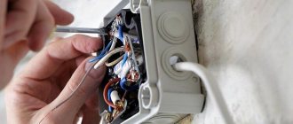
- After some time, several network installers appear at your entrance. As a rule, these are not employees of the Internet provider company, but third-party contractors. They make a hole in the wall in your hallway, run a fiber-optic cable from the distribution panel in the entrance to the apartment, weld it and install an optical socket near the entrance.
Optical socket
- Next, the provider’s adjusters appear, who hang up the optical modem (usually it is provided for rent), connect it with a cable to the socket, and then configure it. The Internet is already in the house, all that remains is to distribute it.
The process is approximately the same in a private house, although the distribution panels will either be located on power line (telecommunication) supports, in wells, or will be absent altogether, and the subscriber cable will be connected from a separate splitter.
These three steps cannot be completed on your own unless you contract with a provider. In addition, according to contracts, networks up to the boundaries of the household or even up to the outlet are serviced by the Internet provider free of charge (if not damaged intentionally); after the boundaries of the separation, the lines are considered the property of the client and all costs of their operation are transferred to him.
That is, you can then act on your own. Here is a typical diagram for distributing the Internet and other services in an apartment.
Connecting ONT in an apartment
The figure below shows a standard diagram for connecting devices to an optical terminal. We’ll immediately analyze its implementation with our own hands, then we’ll tell you how it can be adjusted depending on the capabilities of the equipment, and how to improve it.
Please note that you will have to deal least with optics; you just need to know how to connect a fiber optic cable to a modem, and all other networks are wired.
Standard service connection
Typical network wiring diagram from an optical modem
We will describe in detail all the components of the circuit, since not everything may be clear to a non-specialist.
Optical panel at the entrance
- The optical socket, as in most cases, is located near the entrance to the hallway. It is connected to the distribution panel with a welded optical cable, which was mounted during installation.
- The socket is also connected to the terminal with an optical cable, but it is connected to connectors. This is a patch cord (this is the name given to any fiber optic and wire connecting cables; we will continue to use this term) as a rule, purchased.
Optical patch cord
- A regular telephone cable is used to connect to the telephone. Instead of a telephone socket, it is plugged into an ONT connector, which corresponds to a standard telephone socket, and is routed throughout the apartment to the place where the device is located.
The phone connects directly to the modem
- To connect to a desktop computer, a twisted pair cable (LAN cable) is laid around the apartment, which is connected to the appropriate ONT and PC connectors. The connection is similar to connecting through a regular switch.
- In order to connect a laptop, Wi-Fi is used; for this, a router is placed next to the terminal. In the diagram it is designated as a PPPoE/Wi-Fi router. It is also connected to the ONT using a twisted pair cable.
Wi-Fi router
- The last connection is the TV, for this a digital television receiver is placed next to it (in the Set Top Box diagram, this is the English designation of the device). To connect the receiver to the ONT, twisted pair is again used, with the TV standard HDMI, SCART or Composite (bell) connectors that connect any video devices.
SCART cable
Now let's move on to how to implement this scheme:
- To connect to an outlet, it is best to use a ready-made optical patch cord. Such a short length of wire can be easily purchased at any store. You can make it yourself by purchasing a fiber-optic cable and connectors; we’ll talk about this below when we describe how to move the terminal further from the outlet.
- Next we connect the phone - for this you can also buy a ready-made wire of the required length with connectors. If it’s difficult to choose the length, but you don’t want to make extra, we make it ourselves.
For production we will need:
- a special crimper (crimper) for RJ11 – 14 connectors or a universal one (it will also help when crimping twisted pairs);
- cable of the required length;
- RJ 11 or 14 plugs (they cost a penny);
- tool for cleaning insulation (nipper knife).
Advice. Do not buy a four-core cable for the RJ14 standard; for standard devices, 2 cores are enough.
Then we begin to do the work:
- We remove the top insulation from the wire; for this you can use a knife or wire cutters or crimper blades (if you have them).
- We expose the top insulation by 6-8 millimeters, do not touch the insulation of individual conductors.
- We push them into the body until it stops. Moreover, if we use, as we have already said, a two-core wire, then the conductors should go into the sockets of the two central contacts. Which side will be red and which side will be green is not important, despite the fact that there is a wiring diagram for these connectors, it is not necessary to follow it, telephone sets are not polarity sensitive.
Installing wires into the plug
- Then we insert the connector into the crimper, it should fit correctly into the corresponding socket and squeeze its handles. The bar will slide in, the knives will cut through the insulation of the cores and securely connect the contacts.
Crimping the connector with a crimper
Advice. You can try to crimp the connector without a crimper. To do this, after installing the wires, use a screwdriver with a sharpened tip to press in the knives individually, and then the bar to secure the wire inside. The work must be done carefully, however, the plugs themselves cost a penny, so you can break a few pieces until you can achieve a normal result.
You can also connect your phone using standard short patch cords. To do this, we install sockets near the telephone and ONT.
The conductors in them are usually clamped with terminals. In this case, you need to connect pins 2 and 3 (the red and green wires go to them, just like in a telephone cable). This approach is even more convenient.
Location of contacts in a telephone socket
- We connect the computer using twisted pair. As with a telephone, you can try to find a ready-made cable of the required length or purchase a twisted pair cable and plugs. Crimping occurs in exactly the same way, but with one feature: before installing the conductors into the sockets, you need to develop the ends of the conductors and arrange them in the correct order, it is shown in the figure below.
The order of wires when crimping a twisted pair connector
When preparing a LAN line, do not forget one more feature - twisted pairs have different bandwidths; in order to fully realize the capabilities of optical connections, you need to choose cables of at least category 5, they provide gigabit speed.
Pin numbering on the connector
- Then we connect the television receiver and Wi-Fi router, everything is exactly the same as for a computer - we stretch a twisted pair cable, which we plug into the appropriate connectors. For the latter, if it is located as in the diagram, it is easier to use a ready-made short patch cord. The router will need to be configured, as this is described in its operating instructions.
Simplifying the circuit
The standard scheme is designed for the use of components with minimal functionality. But modern devices have advanced capabilities; we’ll tell you how to use them.
- As a rule, almost all ONT terminals can distribute Wi-Fi, so you can abandon the router.
- TVs with the “Smart TV” function also most often have a LAN input and do not require a receiver.
Modern TVs most often have a twisted pair connector (LAN)
- If you use a radiotelephone, then its base station can be placed next to the terminal and there is no need to run the telephone wire around the house. Moreover, many already have devices in the hallway where the digital socket is most often installed.
In general, using a Wi-Fi connection, you can do away with wires, except for the telephone one. Many TVs include a module for receiving wireless networks, and for a desktop computer you can buy a receiver that is plugged into either a USB connector or installed on the motherboard in PCI slots.
However, when connecting via Wi-Fi, you will not be able to achieve the high speeds that an Internet connection via a fiber optic cable provides. Wireless network capabilities are limited and depend on the distance to the router and the presence of obstacles (walls).
Schema Improvements
Now let's talk about the possibilities of improving the scheme. Much more can be offered. It’s difficult to systematically give the options and describe them all, but we’ll try.
Phone line
Let's start with the simplest thing - a telephone; in a house there may be not one device in the office, as in the diagram, but several, in the bedroom, in the kitchen, in the living room. An optical modem most often has only one RJ 11 (RJ 14) connector. Therefore, the line from it will have to be branched; this can be done in three ways.
- In the location required for branching, install a telephone splitter - a box with three outputs for RJ connectors. Another option is to install a double socket. This option may even be preferable, since later in case of breakdowns, by disconnecting sections, it will be possible to easily find the damaged line.
- Install any suitable terminal box at the splitting point and bifurcate the line using it.
- Connect another one to the telephone cable by soldering or twisting.
Router
A router installed in the hallway may not provide a clear signal (the weaker it is, the lower the data transfer speed) throughout the entire apartment or house, especially if the building area is large. It is advisable to move it closer to the center of housing. True, this option is impossible if the terminal itself distributes Wi-Fi. Alternatively, install a signal amplifier (repeater) closer to the center.
Wi-Fi amplifier (repeater)
LAN lines
Due to the location of the fiber optic terminal, the twisted pair lines are long. Although the signal in them does not attenuate much, it is still more convenient to lay them from the center, especially if there is a lot of equipment connected to the network in the house. The best option, of course, would be to move the ONT terminal itself to the center, but this may not be possible (more on this below).
But there is another possibility - we move the router to the center, as we said above, and do the rest of the wiring from there. Almost all models of these devices, in addition to distributing Wi-Fi, have at least four LAN ports per output and work as switches.
A Wi-Fi router can usually additionally work as a switch with at least four outputs
Also, in the standard scheme, connecting a laptop is assumed only via a wireless network. But we have already said that Wi-Fi does not fully realize the high-speed data transfer capabilities that an optical terminal provides. Therefore, it is advisable to also extend a twisted pair cable to connect it to those places (living room, bedroom, kitchen) where you most often use your laptop.
A television
As we have already said, modern TVs with the “smart” function have connectors for twisted pair cables (LAN) and a Wi-Fi receiver, which makes it possible to eliminate the need for a receiver altogether. It is correct to call such devices not even TVs, but all-in-one computers with the functionality of a TV.
If the TV supports high-definition video or even 3D, it is still better to connect via LAN (due to the possible reduction in speed over the wireless channel). Also, for such devices, if you still use a receiver, then it is better to connect it to the TV to ensure video quality not through the SCART or Composite connectors shown in the diagram, but through HDMI or at least DVI.
HDMI cable
Another feature today in the house is usually not one TV, but several. How to connect them?
If you need high quality, you will have to run a twisted pair cable to everyone, if not, then you can get by with Wi-Fi. Even if the TV receiver itself or its receiver does not support this technology, the wireless adapter costs less than $10.
Wi-Fi adapter
In this subsection of the article we will also answer a frequently asked question - how to connect the optical cable of the TV to the receiver?
In principle, there are receivers that connect directly to the optical network, but they are mainly used for broadcasting on cable networks, that is, for professional use. All home digital television receivers are connected as we described above.
TV receiver
Backup power
The disadvantage of modern high-tech communication lines and not only optical ones is that the terminal devices require connection to the electrical network.
If the old telephone could operate on voltage supplied from the telephone exchange via wires, then the device connected to the terminal is completely dependent on its power supply. That is, if the lights in your house go out, you will not be able to receive or receive calls. Therefore, consider a backup power source for the optical modem.
Uninterruptable power source
Considering that the power consumption of an ONT is usually within 15-20 watts, any uninterruptible power supply unit (the abbreviation UPS is an uninterruptible power supply) is suitable for this purpose.
For example, if an uninterruptible power supply has a battery with a capacity of 9 A/h, then it will be able to provide you with communication for 6-7 hours. During this time, the electrical networks usually repair the damage. For rural areas where power outages are longer, you can choose a unit with a larger battery.
It is advisable to connect a Wi-Fi router to the UPS in addition to the optical modem. Then, if there is a power outage, you will have not only telephone communication, but also the Internet, provided that the batteries of your laptop, tablet or smartphone are charged.
Transfer of ONT terminal
As we have already said, the location of the modem at the front door is not optimal; it is advisable to place it closer to the center of the apartment to improve Wi-Fi communication and reduce the length of wire lines.
Of course, transferring a device can be problematic:
- Perhaps the provider does not allow the modem to be moved independently;
- Subscriber optical cable is quite demanding in terms of installation conditions, it does not like bending under a small radius, it needs to be additionally protected.
But sometimes it is still advisable to rearrange the modem, especially in large apartments with several levels. Let's look at how this can be done, or more precisely, how to lengthen the optical cable.
There are several options:
- Use an optical cable with connectors that correspond to the corresponding connectors in the socket and modem (a kind of patch cord) of great length. The most acceptable option, however, such cables are not found on sale, but you can make them yourself. In addition, with this approach there are no problems with the provider.
- Extend the optical fiber using connecting elements. Below we will look at how this can be done. But note that the signal loss with this method will be greater than with the first option.
- Weld the cable fiber. In fact, it is not that difficult, and we will also look at how it is done. The only problem is that the welding machine costs several thousand dollars and is not worth buying for one or two joints. Although if you are going to continue building optical networks at a professional level...
You can also borrow equipment from a friend or rent it for the day.
By the way, sometimes they ask whether it is possible to install two ONTs in one apartment. In principle, it is possible, but unlike telephone sets, they cannot work in parallel; you will have to pay for two personal accounts. So this choice only makes sense if you need uninterrupted Internet and have the opportunity to connect to the Internet via fiber optic cable from different providers.
By the way, a similar circuit, although wired, was implemented at my home. I am connected via a DSL modem to the republican provider Beltelecom, from which I chose a tariff without a monthly fee. The second connection using a twisted pair cable to the server of a local provider (the director of the enterprise is a neighbor and friend), where the Internet is free. If someone has a breakdown, then I easily switch to reserve.
Next, let's move on to a description of manipulations with optical cables, which will be useful to us if we decide to move the terminal ourselves or simply decide to make a patch cord.
We also offer video connection of an optical cable to help:
Cable cutting and cleaning
A stripper knife is used to remove the outer shell. It has rotating blades that can be used to cut off the outer layer. If the cable is self-supporting, then the cable is removed with cable cutters.
The inner shell should be removed with a specially adjusted stripper knife.
Threads, film, hydrophobe and other elements are removed from the modules. D-Gel solvent is used to remove the hydrophobe. You need to wear gloves when working; the gel is difficult to remove from your hands. Then the modules are wiped with disposable lint-free wipes with solvent, then with alcohol.
At the required distance, the modules are cut with a stripper and removed, leaving the fibers bare. Fiber failure often occurs at this stage.
The welder must work with extreme caution
The length of the optical fiber without sheaths is usually 1.5-2 m; this is required by the instructions for installing the couplings; welding and installation make the work easier.
Fibers must be handled with care. Any damage at any stage of the work leads to the fact that everything has to be done all over again. Before welding, the optical fibers are wiped with 3-4 dry wipes, then a new wipe is moistened in alcohol and wiped clean.
A heat-shrinkable tube is put on the cable for subsequent sealing of the entry into the coupling. When the cable is welded and laid in the coupling, the tube is shrinked using a torch.
The cable is inserted into the coupling, secured, and you can begin measuring the required length of the optical fiber and stripping it. Then a KDZS heat-shrinkable tube is put on it, which will further protect the welding site.
The bare, cleaned end of the optical fiber is inserted into the cleaver. The device cuts the fiber so that the end should be at an angle of 90 ° to the central axis. The permissible error is no more than 1.5 °.
Installation of cable terminations using welded (Splice On) optical connectors
Splice On connectors (SOC) are optical connectors that are installed using a splicing machine directly onto the fiber coming from the cable in such a way that the SOC is placed in the shank of the connector itself.
KDZS (welded joint protection kit) - is a product consisting of two tubes (one inside the other) and a metal or ceramic stiffener placed between them. The upper tube shrinks (reduces in diameter) under the influence of temperature, preventing dust and moisture from entering the fiber welding site). Stiffening element – protects the welding site from bending. The fiber is placed directly into the inner tube so that the welding point is in the middle of the tube. The most common are KDZS with a length of 40 and 60 mm. However, with the development of Splice On technology, micro KDZS with a length of less than 20 mm are also gaining popularity.
Splice On connectors are used in organizing all optical cross-connects and distribution panels where reliable, durable and high-quality optical connections are needed.
Figure 9 – Splice On connector design
This design does not require the use of a splice cassette (in which the KDZS is usually placed) and saves installation time, while maintaining high optical and mechanical characteristics of the connector.
The Splice On connector can confidently be called a factory semi-finished product. After all, at the factory it is completely prepared for installation, which for the fiber-optic line installer consists of making a welded connection (the process is practically no different from welding two fibers together) and assembling the housing (no more complicated than a simple LEGO construction set for preschool children).
Figure 10 – components of the Splice On connector Ilsintech
At the factory, an optical fiber is glued inside the connector ferrule, which protrudes beyond the connector by 2-3 centimeters. From the end side the fiber is cleaved and polished.
However, this technology is no different from installing adhesive connectors on a cable. However, the quality of factory polishing cannot be compared with manual polishing. This is not difficult to verify by inspecting the end of the connector using an optical microscope.
For comparison, you can take the Ilsintech Splice On connector and a regular optical patch cord for 200 rubles (although no manual polishing is used in its manufacture). But even in this case, the difference will be noticeable. Pay attention to the quality of the ferrule polishing (Fig. 10). It shows that in Figure 11b there is a “graininess” of the end of the ferrule, which indicates a low quality of polishing.
Figure 11 – Quality of polishing of the ferrule of the optical connector
As a result, you get something like a pigtail, only with a tail of 2-3 centimeters (Fig. 4), and not 1.5 m, like regular pigtails.
Figure 12 - Splice On SC connector in manufacturer's packaging
Most manufacturers of welding machines for fiber-optic lines offer special holders as an accessory or in the basic set of the welder, into which a connector is placed instead of one of the fibers. To prepare the welding machine for installing the connector, it is enough to remove one of the fiber holders, usually secured with one screw, and install the connector holder in its place. Otherwise, as mentioned above, the process is not much different from welding two fibers together. The SC connector installation technology is as follows:
- The connector shank is placed on the cable. Connector shanks differ depending on the diameter and shape of the cable for installation on which they are intended. The SvyazKomplekt company supplies connectors for cables with a diameter of 900 microns, 2-3 mm, Indor, flat external optical cable 8.1×4.5 mm, 5.4×3.0 mm, external cable with a diameter of 5.0 and 5.8 mm.
Figure 13 – SOC installation: putting the connector shank on the cable
- A mini KDZS from the connector delivery set is attached to the same cable.
Figure 14 – SOC installation: putting the KDZS on the cable
- The optical cable is installed in the fiber holder. Most often, FOCL splicers are supplied with a universal fiber holder, which allows you to clamp both bare 250 µm fiber and 900 µm buffered fibers, 2-3 mm patch cord cable and flat Indor cable. However, when installing connectors, it is more convenient to use removable fiber holders. The manufacturer's assortment includes holders for all common cables, including multi-fiber MPO.
Figure 15 – SOC installation: securing the fiber optic cable to the holder
- Removing the buffer layer. In this example, the buffer layer is removed using a thermal stripper. This method is the most comfortable and does not damage the fiber sheath. However, the same procedure can be performed using a manual buffer layer stripper.
Figure 16 – SOC installation: removing the buffer layer from the optical fiber
- Removing the remaining buffer layer and fat using an alcohol wipe and chipping the optical fiber. A precision cleaver makes a notch (like a glass cutter) and breaks the fiber in such a way that the cleaving angle is 90 ± 5 degrees. This quality of cleavage allows for high-quality welded joints with low insertion losses.
Figure 17 – SOC installation: chipped optical fiber
- Installing the fiber holder into the welding machine
Figure 18 – Installation of the Splice On connector: Installing the holder with fiber into the welding machine
- The optical Splice On connector is installed in the connector holder. The same operations are performed with it as with the optical cable, described in paragraphs 3-6. Optionally, the manufacturer supplies the specified holders. All of them are listed in the “Options and Accessories” tab in the description of welding machines.
Figure 19 – SOC installation: mounting the Splice On connector in the holder
- The fibers from the connector and the optical cable are welded.
Figure 20 – SOC installation: welding the Splice On connector to the cable
- The KDZS is brought to the welding site and is shrinked in the heat-shrink oven of the welding machine. In addition to KDZS, street connectors also have an external protective heat-shrinkable tube. To shrink it, you can use a gas burner or a special shrink oven.
Figure 21 – Installation of SOC: Heat shrinkage of KDZS in the furnace of the welding machine
- The connector is being assembled. First, put on the connector shank (until it clicks slightly)
Figure 22 – SOC installation: appearance of the Splice On connector after heat shrinking
Figure 23 – SOC installation: a shank is put on the connector welded to the optical cable
- Then the outer housing of the connector is put on
Figure 24 – SOC installation: the outer casing is put on the Splice On connector
Figure 25 – SOC installation: ready-to-use Splice On connector
The technology for installing an SC connector using a KF4A welding machine is also shown in this video:
The installation of a reinforced connector on an outdoor cable is carried out in a similar way, but its assembly itself is a little more complicated.
Cable cutting
Equipment for welding fiber-optic lines
The fiber optic cable is cut using the following tools:
Equipment for welding fiber-optic lines
- stripper;
- rope bite;
- screwdrivers;
- side cutters;
- a bottle of alcohol;
- lint-free wipes;
- insulating tape;
- numbers-markers on a self-adhesive basis and others.
If the fiber optic cable was stored in a damp warehouse, approximately a meter of cable should be cut off and discarded. If there is a cable, it must be cut with a cable cutter.
The outer sheath of the cable is removed using a stripper. This knife has a blade that rotates in all directions and can be adjusted according to the thickness of the cable. Using a stripper, a cut is made in a circle on the sheath, then two longitudinal cuts are made along the cable so that the outer covering breaks into two parts.
Removing the outer shell using a stripper
If the next layer is a Kevlar coating, then it is cut with a cable cutter. The metal corrugation is removed using a reinforced knife. The last thin shell is removed with a stripper.
Opened modules are treated with napkins using alcohol. To remove the hydrophobe, use a solvent. The module itself is bitten and removed using a special stripper. All that remains is to make sure that all the optical fibers are not broken.
We measure the fibers for laying in the cassette
We marked them, thought about which modules should go into which cassette and secure them in the cassette with ties. It is advisable to wrap the module in the place of fastening with electrical tape, otherwise it will easily jump out of it. By the way, the insulating tape will not really stick to a surface that is poorly cleaned of hydrophobe.
Next, we measure the fibers for laying in the cassette. At the same time, we remember that the installation path is the simplest - without complex bends. Best of all - in a circle:
It is advisable to avoid such a curved loop in the middle:
- Firstly, the cassette is not designed for such an arrangement of fibers and they will have to be secured with electrical tape, which is incorrect and unreliable.
- Secondly, it complicates the soldering circuit in already complex cases and leads to errors.
Although sometimes, of course, you cannot do without this method.
Think in advance about how the fiber will fit into the cassette and cut it to the required length. Otherwise, it may not be enough in the end.
Optical cable classification
Optical cables can be classified:
By structure:
- standard cables having a sheath with modular tubes;
- modern multilayer cables, which are endowed with two-level protection and other advantages.
By area of application:
- for outdoor use;
- for internal routing (this option is rarely used exclusively in data centers).
According to operating conditions:
- hanging;
- ground;
- for cable sewer systems;
- underwater;
- for power lines.
The most popular are overhead, ground cables, thin, paired patch cords. Cables with corrugated armor and cables are used a little less frequently. Other types of fiber optic cables are rare.
Tools used
As with soldering fiber optics, cutting a cable requires a special set of tools.
The standard set of tools for an assembler-soldier includes:
- set of strippers;
- screwdriver set;
- pliers;
- rope bites;
- set of knives;
- other additional tools for various work situations.
Today there are many tool sets from different manufacturers, with different configurations. They can be fully equipped with the necessary tools or contain only basic ones. Many manufacturers do not pay much attention to the strength of tool storage cases, but only to their appearance. They are made of fiberboard and covered with textured foil. Accordingly, such cases do not withstand long operating conditions under difficult operating conditions and require periodic repairs.
And some of the tools from the set may also be of poor quality, and some may not be needed at all. Expensive, high-quality branded consumables can be replaced with cheaper products.
We clean the varnish coating on the fibers
A stripper is used to remove varnish from fibers. This is an expensive tool designed specifically for nail polish removal - precise and high quality. If you use it for other purposes during your work, you will soon have to shell out money for a new one.
You need to strip about 3 centimeters. The main thing is not to break the optical fiber, since we have already measured its length and cut it off, there is no reserve.
So we have marked, cleaned optical fibers of the required length, with KDZS put on (on half of them). Now comes the fun part.
Optical fiber connection methods
The fiber optic industry does not stand still: optical fiber splicing is constantly being improved, the methods of its implementation and the consumables used are changing.
Selecting the optimal fiber connection technology for each specific case is important from the point of view of reducing financial costs and increasing productivity.
Inexperienced welders do not always know exactly what needs to be taken into account when working with this material
When choosing a fiber splicing technology, it is important to consider the following aspects:
When choosing a fiber splicing technology, it is important to consider the following aspects:
- optimal speed of operations;
- the time period required to prepare the optical fiber for welding;
- amount of time for welding cables;
- cost of work;
- experience of specialists.
When laying fiber optic fabric, there is always a need to weld the optical cable into a single line.
Coupling for connecting fiber optics.
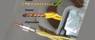
Today, the most common ways to perform this operation are:
- using mechanical connectors;
- directly on the optical cross-country;
- welding of optical fibers using special equipment.
The first method is used extremely rarely, because the gel in mechanical connectors dries out over time, which worsens the parameters of cable joints. The second is quick and easy to make, but the best fiber optic cable connections are made by welding.
This technology is characterized by the best indicators in terms of quality, durability, and reliability of the created connections.
First, you will need to cut an optical cable of 6-8 fibers connected in a module and covered with insulating material. The insulation is removed and the fibers are cleaned using special alcohol-based products.
After this, the fibers are placed in a welding machine for subsequent automatic welding
It is important to control the strength of the seams formed at the junctions of optical fibers. The welded elements will need to be placed in an optical coupling or cross cassette
On a note! The simplicity of this technology allows it to be performed even by an inexperienced welder who has personally observed this process being performed by a specialist. But the main thing is to have a special welding machine: conventional models will not cope with this task.
CONTENT:
- Design and location of the optical connector
- Installation of optical connectors using pigtails
- Installation of cable terminations using welded (Splice On) optical connectors
- Installation of reinforced Splice On connectors for installation on outdoor optical cable
- Installation of cable terminations using Fast connectors (FAOC, mechanical optical connectors) for fiber optics
- Comparative table of advantages and disadvantages of optical connector installation methods
- Recommendations for choosing optical connector mounting technology
Difficulties in splicing fiber optics
A fiber optic network, according to modern experts, is the best medium for high-speed transmission of various types of information. The material used to create such an environment is lightweight and low susceptibility to interference and radiation.
It is not capable of causing any obstacles to the path of information from one point to another, and due to its low power it is characterized by absolute electrical safety.
Since fiber optic materials provide soldered connections with high functionality and impressive efficiency, their scope of application is growing every day.
Today, optical communication lines are widely used to transmit information over long distances, as well as for wiring in one specific building. But it is not possible to lay such lines without splicing fiber optics.
Welding of optical fiber is carried out using special welding machines that allow you to perform the entire range of current operations: from connection to protecting the welded area.
A conventional welding machine will not be suitable for such operations, since it will not be able to provide the master with minimal attenuation at the welding site.
The equipment needed to work with optical fiber operates on the same principle: the ends of the optical fibers are heated to a certain melting point using an electric arc, and then connected together.
It is difficult for an inexperienced welder to accurately adjust the edges of the cables being joined, since they lose functionality if there are errors during adjustment.
When working with fiber optic cables, it is extremely important to pay attention to their colors when welding. It is in addition to the marking and indicates the specific identity of the cable.
Thus, twelve different color claddings are used to identify optical fibers, allowing a specialist to quickly identify the type and purpose of the fiber, even if it is mixed with other cables in a large bundle.
On a note! The problematic issue is that today there is no single international standard for marking fiber optic cables. This situation provokes unpleasant mistakes that young professionals can make.
A little theory
Let's start with the basics in order to understand what we will have to face, because optical communication technology differs from the usual and familiar wires, both in the operating principle and in the installation methods. Of course, this section can be omitted and proceed directly to solving practical problems, but still, knowing the theory, it is easier to solve many problems that arise in practice. We will try not to bother you with complex terms, but to explain everything simply and popularly.
How data transmission via optical fiber works
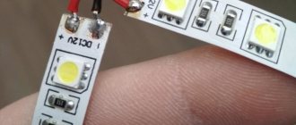
This is how light is transmitted through optical fiber
Transmitting a signal through ordinary wires using electric current runs into two obstacles that limit the speed limit.
- A high frequency signal fades quickly over a long distance.
- High frequency currents have large energy losses through radiation into the environment.
- Nearby wires and equipment interfere with the signal.
These negative factors are combated by using intermediate amplifiers, screens, and twisting wires. But there is a limit to everything. Today, increasing the speed of information transfer is mainly solved by dividing it into parallel streams. For example, USB 3.0 differs from the earlier USB 2.0 in that it uses more than one pair of wires to transfer data.
The issue could be radically resolved only with the help of fiber optic cables. In them, the signal is transmitted using light, more precisely laser radiation, which is weakly attenuated over long distances. Glass fibers are used for communication, in which, due to the specially selected properties of the core and outer layer, the effect of complete reflection of the light beam is manifested.
Also, due to their small diameter, they are flexible (we also encounter thin flexible glass fibers in such familiar materials as glass wool and fiberglass).
The system works extremely simply: on one side of the cable, laser radiation is modulated, encoding information in it, which is decrypted by a photoreceiver at the other end. One optical fiber can transmit multiple streams, using lasers with different spectrums in parallel.
The transmission speed over optical fiber is orders of magnitude higher than the capabilities of metal conductors and reaches several terra bits per second.
Optical fiber has other advantages:
- Absolute protection from external interference ; it is impossible to direct an extraneous signal to such a cable.
- Due to the absence of metal conductors, such lines cannot be damaged by insulation breakdown from high voltage , so they are also safe for users.
- Modern fiber optic cable has a small diameter and takes up a lot of space in trays and sewers.
- It is impossible to read information without damaging the cable or impairing its performance using known methods (for example, detecting electromagnetic radiation).
Another advantage of optical fiber is that it is not of interest to attackers, since it does not contain non-ferrous metals.
But there are also some disadvantages:
- such cables cannot be connected by conventional soldering or twisting; it is necessary to weld glass or use special connecting elements;
- fiberglass cables cannot be bent to a small radius;
- equipment for receiving and transmitting is complex, although with proven and mass production, as with any electronics, its price is constantly decreasing.
How PON technology works
At first glance, building a subscriber network can be done in two ways:
- Route cables from the base station to each user. This is how a standard city network works - pairs of wires go from the PBX to each telephone.
- Construct several high-capacity trunk lines to which active switches are connected - switches that distribute access between subscribers. This is how the first networks were built using twisted pairs (LAN) and later fiber optics as backbone lines. For example, a fiber optic line ran to the house, access to which was distributed among apartments using twisted pairs connected through switches. Such networks were called FTTB (Fiber To Building) - fiber to the building.
PON technology works on a slightly different principle:
- Active equipment is installed only at the provider and client.
- Up to 128 receivers can be connected to one fiber. The network is built on the principle of a tree, where branches go from the line, and from them branches of the second order, and so on.
- All subscriber devices connected to the same fiber gain access to the network in a time-shared manner. That is, a package of information is immediately transmitted to one client, then to the second, and so on in turn. Due to the large capacity of the line, this does not in any way reduce the data transfer speed. Communication is also carried out in the opposite direction, but a different wavelength of laser radiation is used.
This approach became possible due to the use of special devices - splitters. They divide the flow of one fiber into several fibers. Radiation losses, of course, are large, but they are compensated by the use of powerful lasers; today their price is not that high.
The advantages of splitters are that they are relatively simple, do not require connection to electrical networks (this is a passive element, hence the name of the technology) and maintenance.
These features of PON technology allow the development of networks in any conditions. If for older methods of Internet distribution, unlike in the city, where you can place ordinary switches and servers without problems in any attic or basement and there are no problems with connecting the power supply, there were great difficulties in rural areas, for PON there are no such problems.
The splitter can be hung on any wall or power line support and even placed in a well; the devices are not afraid of moisture.
PON network
To make it more clear how PON technology works, here is a diagram of how such a network is organized.
PON network diagram
Let's explain the diagram a little:
- The Internet provider or PBX has an OLT (in English - Optical Linear Terminal - Optical Linear Terminal) from which the distribution takes place. Cable lines are connected to it. This is a fairly compact device; the photo below shows a rack that can serve several thousand subscribers.
OLT rack
- Several cables extend from each OLT; the diagram shows only one for four cores. They are distributed throughout the serviced area in cable ducts, along supports or in another way.
Thanks to the high power of lasers, the length of cables can reach up to 60 kilometers, although manufacturers usually guarantee a high-quality signal at a distance of up to 20 km, but this is quite enough for an average city.
- A splitter is hung on each core (in the diagram these are boxes labeled Spliter), from which branches go either to other splitters or directly to clients. The diagram shows a branching of two cables at the top and four at the bottom, but the signal can branch into more cables, although multi-output devices are usually rarely used.
The simplest splitter
Splitter dividing signal into 16 fibers
- After the first splitter, several more can be installed.
- At the end of the line, the subscriber has an ONU (in English Optical Network Unit - Optical Network Unit) it can also be called ONT (in English Optical Network Terminal - Optical Network Terminal) to which you can connect a LAN cable. Sometimes the device is called an optical modem.
Optical modem
- In addition to LAN connections, ONUs almost always have sockets for a telephone, since almost always a PON connection provides a package of services: Internet, telephone, television.
As can be seen from the diagram, the network can be easily developed without high costs. For example, in the upper part, instead of the first ONU, install another splitter, to which two subscribers can be connected. You can also replace the two-channel splitters with four-channel ones, such as those at the bottom of the circuit.
Cable structure
The essence of welding technology is to connect the ends of an optical fiber and then heat them until they melt and join into a single whole.
For those who have worked with glass, this will seem elementary, but you need to keep in mind that the fiber through which data is transmitted has a diameter of 9 microns (10 times thinner than a human hair) and it is required that the signal attenuation does not exceed hundredths of a decibel.
To understand the essence of the welding process, you need to understand the structure of the optical cable. It is a complex structure, in the center of which there is a glass thread with a diameter of 125 microns. This is just a shell of a 9 micron thread made of ultra-pure glass, which is the information carrier.
The outer glass has a different refractive index than the inner glass. Thanks to this, the light spreads only along the inner thread, reflecting from the walls.
To protect the optical fiber from external influences, it is coated with varnish and placed in module tubes with a hydrophobic gel. In addition to this, the modules are covered with a protective film.
As additional protection from moisture, everything is covered with plastic film. Next comes armor made of Kevlar threads or steel wire, which is covered with a thick layer of polyethylene.
Welders
For welding optical fibers in Russia, devices most often used are from Japanese companies Fujikura, Sumitomo and Chinese Jilong. Japanese manufacturers initially showed themselves excellently in this area, their machines are the best, but the Chinese are stepping on their heels and producing decent welding machines at low prices.
To obtain high-quality welding of an optical fiber, you need a welding machine capable of aligning the fibers not only along the cladding, but also along the core.
They have several servomotors that can move the fiber in all planes. This allows you to achieve the greatest accuracy in connecting fiber optics. Most of the products from the above-mentioned companies can produce high-quality alignment.
Where the requirements are not as stringent as on trunk communication lines, welding machines with sheath adjustment can be used. The optical fiber in these devices is fed through V-shaped grooves.
If there is an eccentricity of the central core or a scratch on the groove, the welding quality will be lower, and accordingly the attenuation will be greater. Japanese devices are universal and work with almost all types of fiber.
Distributing the fibers in the cassette
Standard cassettes are designed for 32 fibers. Therefore, if our cable consists of 4 modules of 8 fibers, everything is easily calculated:
- The fibers of the 1st and 2nd modules of one cable are welded with similar ones of the second cable and are placed in the upper cradle of the cassette. (16 fibers)
- The 3rd and 4th modules are in the lower cradle.
In simple cases, it is of course easy to achieve something like this:
It's more difficult when you have a 64 fiber cable . If they are both the same, each with 8 modules of 8 fibers, then you can still get out by dividing them into two cassettes:
- The first four modules of the first and second cable are welded in one cassette;
- The last four modules go to the second;
- It doesn’t matter which half goes to the top and which half goes to the bottom;
If you have two cables with different numbers of fibers in the modules, or 3-4 different cables are welded, then very careful planning of fiber routing is necessary.
Note that the fibers that go to another cassette (for example, excess fibers due to the difference in the number of fibers in the modules) between the cassettes should be placed in a hard plastic tube, which, if necessary, can be replaced with a dropper tube. You cannot use the empty shell of the modules for this, because it is brittle, and besides, you cannot really clean the hydrophobe inside it, much less just let the fibers in.
Fiber optic cable cutting
The main task when cutting a fiber optic cable is to maintain the length of its components as indicated in the coupling instructions. Therefore, in some cases it is necessary to leave long power components designed to be secured in the coupling, and sometimes this is not necessary. In some cases, you need to make a “pigtail” out of Kevlar and secure it with a screw; it is better not to cut the Kevlar. These nuances depend on the design features of the coupling of each cable. So, the stages of completing the work:
The hydrophobic protective layer is first removed from the fibers. To do this, they are wiped with special wipes: first dry, then treated with alcohol.
It is quite important to follow this rule, since a large amount of hydrophobic material will remain on the first napkins. But when it is no longer possible to remove minor remnants of the protective layer with a dry cloth, alcohol will help
It will easily dissolve hydrophobic particles and instantly evaporate from the surface of the fiber.
It should be noted that the cleanliness of the fibers, especially their ends, is the key to high-quality optical fiber welding. When working with microns, even the slightest contamination is unacceptable! It is imperative to check the fibers for the integrity of the varnish coating and the absence of broken areas
If there is damage to the varnish coating, then it is recommended to redo such a cable (but it should not be broken)
It is imperative to check the fibers for the integrity of the varnish coating and the absence of broken areas. If there is damage to the varnish coating, then it is recommended to redo such a cable (but it should not be broken).
- The coupling kit includes a special heat shrink, which is put on an already cut cable (which beginners often forget about). If the cable will be clamped with rubber and sealant, then heat shrinkage is not needed. To ensure a tight connection between the cable and the coupling, it is recommended to use a hair dryer, a soldering iron, or a torch to shrink it. But the most practical is considered to be a small burner, mounted on a gas canister.
Before you start welding an optical cable, it is recommended to purchase additional coarse sandpaper. This will help ensure better adhesion to the adhesive.
FAST Connector installation technology (fast connector, mechanical connector)
Despite the fact that optical Fast connectors from different manufacturers are built on the same principle, there are still some differences between them. The main differences lie in the way the cable is secured. Therefore, the installation technology itself does not differ significantly depending on the manufacturer of a particular connector. Let's look at the installation technology using the Fast connector produced by Tempo Communication (USA) as an example.
Figure 27 – Tempo Communication fast connector delivery kit
- Place the connector shank onto the fiber optic. Remove 40 mm of cable sheath and protective buffer. You can remove the 3 mm cable sheath and 900 µm buffer layer using a buffer layer stripper (with three grooves).
Figure 28 – Installation of the optical Fast connector: removing the upper cable sheath
- Acrylic varnish is removed from the fiber in a section of 20 mm from the end of the fiber, after which the fiber must be wiped with a lint-free cloth soaked in isopropyl alcohol (Fig. 29).
Figure 29 – Removing the buffer layer from an optical fiber
Figure 30 – Removing the buffer layer from the optical fiber
- Chop the optical fiber using a precision cleaver. The higher the quality of the optical fiber, the longer the lifespan of the fast connector.
Figure 31 – Cleaving an optical fiber using a precision cleaver Greenlee 920CL
Figure 32 – Cleaving an optical fiber using a precision cleaver from a third-party manufacturer
Tempo has adapted its 920CL cleavers to work with Fast connectors. Thus, as an accessory, they come with a special holder for a patch cord cable. In this case, it is not necessary to measure 20 mm before removing the buffer layer. Its removal occurs as shown in Figure 30. Next, the same holder is installed in the 920CL cleaver to perform cleavage.
When installing fiber in a cleaver (except Greenlee 920CL), ensure that the 250 micron fiber buffer ends at the "10" on the ruler (Figure 7). Thus, the distance from the end of the buffer layer (acrylic varnish) to the end of the fiber after chopping will be 10 mm.
If the Fast connector is used to quickly restore network functionality and then replace it with a Splice On connector or pigtail, then the cleaving can be done using a cheaper manual cleaver. As long as there is enough immersion gel in the connector, the connector will provide acceptable connection performance. At the same time, it is worth considering that the quality of cleavage with a manual cleaver is much worse than with a precision cleaver. Accordingly, if, if the gel dries out, losses and reflection simply increase in a connector mounted using a precision cleaver, then if a manual cleaver is used, it will stop working altogether. And failure will occur much earlier. Typically, the life span of the connector in this case is no more than 1 – 1.5 months. This period is quite enough to find the time and opportunity to replace the mechanical connection with a more reliable one - a welded one.
- The cleaved optical fiber is inserted into the connector all the way until the part of the fiber located in the connector shank begins to bend. This means that the end of the fiber of the terminated cable is in contact with the fiber glued into the connector at the factory.
Figure 33 – Inserting optical fiber into the Fast connector
- To fix the fiber in this position, you must remove the mounting clamp, as shown in Figure 34.
Figure 34 – Fixing the fiber in the connector
After this, you need to lightly press the connector body against the fiber so that the fiber is aligned at the bend (Figure 33).
- The cable itself is fixed in the connector using the connector shank. Twist the shank so that it clamps the Kevlar threads. The remaining threads must be trimmed using scissors.
Figure 35 – Fixing the cable in the connector and final assembly of the connector
Conclusion: As you can see, installing a quick connector is very simple, requires minimal tools and can be completed in a very short time. However, the fragility of such a connection imposes some restrictions on the use of this technology. Therefore, the most preferred use of Fast connectors is the rapid elimination of breakdowns when there is no welding machine at hand.
The simplest set of tools for installing such a connector could be: a buffer layer stripper, a hand cleaver, scissors or a knife, and alcohol wipes.
Weld quality check
During the welding process, it is necessary to pay attention to the shape of the weld arc. Perfect welding is almost invisible to the naked eye
If the arc is crooked, it is recommended to chop off the weld and repeat the work again.
If the welding machine produces significant signal attenuation at the seam site (more than 0.1 dB), then it is better to digest the fibers. But even if the signal loss is insignificant, the total of several welds can still result in signal loss at the other end of the cable.
Reflectometer
The attenuation of the entire optical path, consisting of several couplings and cross-connects, is checked using a reflectometer. This is a measuring device that sends a pulse along an optical path and analyzes its scattering and reflection. With its help, you can see the total length of the path and the signal attenuation in a separate section. This way, it is possible to find out exactly where the fiber optic cable is causing a signal break or significant attenuation. The instrument saves measurements in an electronic file, allowing dispersion analysis to be carried out some time after testing.
Installation of optical connectors using pigtails
Figure 5 – optical pigtails: a) in a dense buffer; b) in a free buffer
An optical pigtail (Pig tail - literal translation - pig's tail) is an optical cable 1.5 m long terminated on one side.
Typically pigtails have a buffer shell diameter of 0.9 mm. Moreover, they are supplied both in a dense buffer (Fig. 5a) and in a free buffer (Fig. 5b). The main difference between these two types of buffer layer is its removal. The dense buffer is removed only together with the 250 micron acrylic coating of the fiber. The floating pigtail buffer is removed separately from the fiber varnish coating.
Figure 6 – optical splice cassette
To save space in the splice cassette, some operators require the 900 micron jacket to be removed from the cable before installation.
A splice cassette is a structural element of any optical distribution box or optical coupling. It has seats for installing KDZS, as well as space for placing a supply of fiber with an allowable bending radius.
Pigtails also differ in the type of optical fiber used in them, the type of housing and the polishing of the installed optical connector.
Figure 7 – optical box (ODF): a) on the operator’s side; b) on the subscriber side
To terminate an optical fiber using a pigtail, you must do the following:
- Place a protective sleeve - KDZS - on one of the fibers to be welded (fiber from a cable or pigtail). It is worth noting that the KDZS (welded joint protection kit) is a product consisting of two tubes (one inside the other) and a metal or ceramic stiffener placed between them. The upper tube shrinks (reduces in diameter) under the influence of temperature, preventing dust and moisture from entering the fiber welding site). Stiffening element – protects the welding site from bending. The most common are KDZS with a length of 40 and 60 mm. However, with the development of Splice On technology, micro KDZS with a length of less than 20 mm are also gaining popularity.
- Remove the buffer layer of the cable fiber and pigtail using a buffer layer stripper
- Wipe the fibers with a lint-free cloth soaked in isopropyl or ethyl alcohol 96%
- Cleaving fibers using a precision cleaver
- Weld the fibers using a welding machine
- Slide the KDZS sleeve (welded joint protection kit) onto the welding site
- Perform heat shrinkage of the KDZS in the oven of the welding machine
- Mark the KDZS using a marker or a special sticker with a serial number
- Install the KDZS into a special clamp on the splice cassette
- Place a supply of optical fibers in a splice cassette
As you can see, the procedure is quite simple. The use of this method of installing connectors on fiber optics is quite justified in operator cross-connections or large distribution boxes. However, on the subscriber side everything is not so simple.
Firstly, on the subscriber side, most often only one, or at most two, fibers are terminated. Using a large ODF (as depicted in Figure 7a) does not make sense.
Second, there is much less space in a small PO box, which results in large bends in the fiber optic cable. And if for pigtails, which are most often made on the basis of the G.657 standard fiber, which is less sensitive to bending, this is not very critical, then for cable fiber (another standard) it is noticeable. Additional signal loss occurs where the fiber bends. This can be easily verified by illuminating such a fiber with a damage visualizer (red light source).
Figure 8 – loss of optical signal power at the macrobend location
Therefore, on the subscriber side, it is recommended to terminate the cable using Splice-On connectors (the KDZS is located in the shank of the connector itself) with a minimum number of spare loops.
Nuances of fiber optic welding
If the cable is multicore, the optical fiber sheath is made in different colors to make it easier to weld individual conductors. After this, they are placed in a special coupling. In the process of chipping the conductor, glass particles are formed; they are collected immediately, because it is easy to be injured by the transparent fiber.
Be careful when cleaning the insulation - the wire core is very fragile. If there is any damage, you will have to start the process again
Before inserting the ends into the welding machine, they are thoroughly degreased and dried; the work area should not be dusty. Any extraneous inclusion increases the loss of power of the transmitted signal.
Installation of reinforced Splice On connectors for installation on outdoor optical cable
Reinforced Splice On connectors are a unique solution for organizing optical cable distribution in FTTx and PON networks. They are installed using a welding machine on street cables of round (5.0 mm and 5.8 mm) and flat (8.1×4.5 mm and 5.4×3.0 mm) sections. Thanks to the design features of Splice On, the connectors are resistant to temperature, sun and precipitation, so the distribution box can be installed directly on a light pole.
Features of reinforced Splice On connectors:
- Low insertion loss: ≤0.15dB
- Return Loss: >60 dB (APC)
- Hull resistance to direct tension (0°): 20 kgf / 10 min
- Adapter resistance to direct tension (0°): 11.3 kgf / 60 sec
- Adapter resistance to lateral stretch (0°): 6.8 kgf / 60 sec
- Resistance to water penetration: 3.04 m for at least 7 days
The technology for installing a reinforced connector on an outdoor fiber-optic cable is demonstrated in the video:
As follows from the video, the dimensions of the external heat-shrinkable tubes do not fit into the standard furnace of the welding machine. To shrink them, you can use a gas burner (as in the video) or a special shrink oven.
Fiber Splicing Equipment
Choosing a welding machine for fiber-optic lines comes down to determining the type of welding:
- manual;
- semi-automatic;
- automatic.
Manual devices do not allow high-quality and quick work on connecting cables. The labor-intensive mixing process is controlled under a microscope.
It was replaced by semi-automatic equipment. All work is done under a microscope, and the operator can evaluate the quality of the automatic connection of the welding site. This device significantly saves the technician’s time.
A negative characteristic of the device is that optical cords cannot be welded. This part of the work is done manually by the master.
A positive assessment of the device is its low cost compared to fully automatic welding machines.
A fully automated device has recently appeared on the market. It allows you to significantly save operator time. The built-in microscope allows the master to control the cooking process. The disadvantage of modern models is their high price.
Production of welding works
For this, a special welding machine is used. The procedure for performing the fiber connection operation is approximately the same for all types of machines:
- After switching on, the clamp cover opens, the prepared 16 mm conductor is laid along the installed limiters, with a gap of 1-1.5 mm. to the junction. This operation requires visual control;
- Close the lid and press the start button. The connection process occurs automatically with the process displayed on the monitor screen.
- At the end of the connection, signal losses at the junction are automatically determined; a decrease in the level by 0.022 dc (Decibel) is considered a good result.
Then the KDZS protective tube is placed over the joint. To heat the heat-shrinkable tube, the welding device has a special compartment - a heat stove, where the “raw” insulation is placed. After warming up (about 40 seconds), the device gives a ready signal - you can take out the finished cable sheet. The process of joining fiberglass is clearly shown in the video.