What electrical characteristics ensure safe operation of the ground loop?
The protective function of the circuit is based on the phenomenon that fault current flows along the path of least resistance.
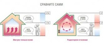
Due to damage to the insulation, a phase potential may appear on the body of any household appliance. In the old TN-C grounding system, it will flow through the body of the person who touches it.
The severity of an electrical injury depends on many factors, but can also lead to fatal consequences.
In the TN-S power supply circuit, an artificially created PE conductor through the grounding loop removes dangerous potential and protects a person from electric shock.
For optimal operation of the circuit, it is necessary to take into account:
- resistance to spreading;
- touch and step tension;
- soil condition based on its resistivity;
- electrical characteristics of selected materials and their resistance to aggressive soil environments;
- circuit design, which must be calculated according to standards and verified by electrical measurements with high-precision instruments.
Resistance of the grounding device in electrical installations up to 1000 V: what components does it consist of?
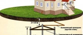
Any grounding loop consists of vertical or horizontal grounding conductors (electrodes) located in the ground. An emergency current flows through the contact they create.
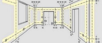
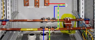
Vertical electrodes are buried in the soil, spaced at a certain distance, and united by a horizontal ground electrode connected to the main busbar of the building.
For a private house, one vertical ground electrode is rarely used due to the resistance to current flow.
Let us assume that there is a structure with one vertical electrode connected to it, located in the soil. There is a metal short circuit to the main bus. For simplicity, we neglect the resistance of the grounding conductor.
The short circuit current begins to flow to the ground potential along the electrode and is distributed from it evenly in all directions. In this case, the maximum current density will be created at the ground electrode itself, and with distance from it it will begin to decrease.
The passage of current through an ever-increasing surface of the earth weakens its magnitude. Voltage also has the greatest value at the electrode, and with a constant decrease in the current value it drops. Here Ohm's simple law comes into play.
At the boundary of a certain area, called the spreading zone, the stress decreases to almost zero from its maximum value. In this way, we obtained points of zero potential located on opposite sides of the electrode, at which U=0.
The resistance of the grounding device Rз is the resistance of the land between the points of zero potential. It is calculated using the formula Rз=Uф/Iкз.
Its value is very little affected by the resistance of the metal parts of the grounding conductors with the busbar and the contacts of the electrodes with the ground - they are very small. The issue of reducing it is solved by changing the contour design and soil characteristics.
This indicator can be improved by installing an additional electrode. However, it must be mounted in a certain way.
If two electrodes are placed side by side, the area of the spreading zone remains virtually unchanged. The short circuit current flows into the same area of soil. Therefore, grounding conductors must be spaced over a greater distance.
In this case, the short-circuit current will flow from each electrode, dividing into two flows, and a space will form between them where they influence each other. This is called the shielding zone. To assess its characteristics, correction factors have been introduced.
The second method of improving the resistance of a grounding device is based on increasing the length of the vertical electrode and burying it in the ground to 30 meters. The technology of this method is given at the end of the article.
Several vertical electrodes are welded in the soil to a metal strip (horizontal ground electrode). It also affects the flow of emergency current and is assessed by an individual coefficient.
Its value depends on the number of electrodes in the circuit and the ratio of the distance between them to their length. The data is summarized in a table.
Thus, the electrical characteristics of the created circuit strongly depend on the configuration and location of vertical and horizontal ground electrodes and their penetration into the ground.
The owner of a private house needs to evaluate the resistance of the grounding device in electrical installations up to 1000 V and make a preliminary calculation on paper before starting to assemble the structure. To do this, you need to understand from which processes the parameters specified in the project are taken.
Touch and step voltage: what is it and how does it affect ground loop design
Touch voltage is described in clause PUE 1.7.24. Its value is included in the formulas for calculating the ground loop resistance.
Let’s imagine that a phase potential U appears on the body of some equipment and a person with body resistance R touches it.
Current It will begin to flow through it, which is determined by Ohm’s law. The magnitude of the applied voltage depends on the place where the contact is created, the distance from the maximum value of U, and is designated by the term touch (Upr).
Since human safety depends on Upr, strict standards have been introduced for it. When creating an electrical project for a facility, it is subject to strict restrictions that affect safety. They are taken into account in the permissible resistance parameters of the grounding device.
Step voltage
Another number of factors that influence the calculation of the circuit is taking into account those processes that occur directly on the ground during the flow of emergency current, distributed within the area where a person may accidentally find himself. They are taken into account by the step voltage.
At the epicenter of the discharge, the maximum voltage is applied, and its value gradually decreases with increasing distance to zero. When a person moves in this zone, a potential difference will arise between his legs.
It increases as you approach the discharge site, and under certain conditions can lead to electrical injury: the closer to the center, the more dangerous.
The step voltage term Ush is included in clause PUE 1.7.25. It is strictly standardized by the formulas for calculating the design of grounding devices.
At industrial facilities, expensive special protections are usually used that quickly turn off emergency modes when the step voltage has a very short time to manifest itself.
There are no such devices in a private home. Therefore, increased demands are placed on the quality of the circuit. The owner needs to consider its location and the route of the horizontal ground electrode.
The stress of touch and step is sought to be kept as minimal as possible to ensure increased human safety. They are taken into account by the PUE standards.
What standards for resistance to spreading are included in the PUE and why?
To create a reliable circuit for a private home, you should understand that it does not work on its own, but as part of the entire grounding system of an electrical installation, starting from an industrial transformer substation.
Safety depends on the type of neutral point of the transformer transformer and the speed of emergency response.
At industrial facilities that require prompt shutdown of emergencies, an effectively grounded neutral is created, which makes it possible to quickly shut down short-circuit currents in case of single-phase ground faults. To do this, its resistance, taking into account the influence of all natural and artificial grounding conductors, should not exceed 0.5 Ohm. (Clause 1.7.90.)
A household electrical network of 380/220 volts is usually created with a solidly grounded neutral. Its safety in some part can be improved by an isolation transformer.
A network with an isolated neutral is created behind it. But we are now considering another issue.
A transformer substation connected according to the usual circuit with a grounded neutral must operate in the mode provided for in clause PUE 1.7.101.
This means that when powering a private house with a voltage of 380/220 volts, the total resistance of the entire chain of grounding devices must fall within the standard of less than 4 ohms. This value is influenced by all repeated grounding of overhead lines and natural grounding.
The latter include reinforced concrete foundations of buildings and other metal structures buried in the ground. Their task is to provide long-term electrical contact with the ground.
Repeated line grounding conductors are distributed among overhead line supports to ensure a sufficient magnitude of single-phase fault current that the current protection must sense. They are placed at the entrance to the building.
All these groundings should collectively provide a resistance value of 0.4 Ohm at the transformer substation.
When overhead lines and transformer transformers are put into operation, then any grounding installed on them is in operation. It is impossible to measure its resistance separately and is very dangerous: it is part of the electrical circuit.
Now let's continue our consideration of paragraph PUE 1.7.107. for the grounding device of a private house. Other standards are already given here.
For the ground electrode we are creating, a value of 30 Ohms has been introduced. The ground loop can be disconnected from the main shield and its resistance can be measured. We understand that in operation it participates with all the repeated and natural grounding conductors of the circuit and provides 4 Ohms for the transformer at the transformer substation.
But it's not that simple. We will need to fulfill one more safety condition: the resistance of the nearest repeated grounding electrode must be 10 Ohms. This is stated in paragraph PUE 1.7.103.
However, providing these 10 and 30 Ohms in simple ways is not always possible due to the physical condition of the soil.
Types of soils and their resistivity: what requires mandatory consideration
Our circuit will be driven into the ground, which serves as a conductor of electric current. Its conductivity depends on many factors and is normalized by the resistivity value.
For example, rocky soil has very poor characteristics. Working on it is a bad idea. Standardized parameters and possible limits of their deviation are placed in the table.
This information is presented as indicative for making an approximate calculation. When creating a contour design, it is advisable to clarify them on a specific area.
The moister the soil and the more different salts it contains, the better its resistivity. However, salt solutions are an aggressive environment that causes corrosion of metals.
It is the constant fluctuations in moisture, depending on the time of year and weather conditions, that cause large deviations in resistivity from the average value.
In cold weather, water turns into ice, and it conducts electricity rather poorly. During hot weather, the soil dries out. Winter and summer are the most unfavorable periods for the operation of the ground loop.
Therefore, these seasons are used to carry out control measurements of spreading resistance.
The soil does not have a uniform structure. When going deep into the soil, all sorts of surprises can occur. It is impossible to foresee them. Especially at great depth.
For example, on top of the soil there may be a layer of black soil, and under it there may be loam or sandy loam, stones.
You can roughly estimate the composition of the soil yourself. To do this, they take a piece of it from a depth of about a meter and try to roll it into a “sausage” between their palms. If its thickness corresponds to a match, then it is clay.
You can't roll anything out of sand; it crumbles. You can make sausages about a centimeter thick from loam. The sandy loam rolls up into slightly larger pieces and immediately falls apart.
The method is approximate, but it allows you to obtain data for calculating the project. More accurately, these results are provided by instruments designed to measure the electrical resistance of soils. They are handled by specialists from electrical laboratories.
Since soil resistivity strongly depends on the season, for a more accurate calculation of the contour, seasonal coefficients have been introduced that also take into account the four areas of residence.
Requirements for materials for the ground loop that you must know
High-quality electrical contact between the metal of the electrodes and the soil is created not by burying the structure, but by driving the rods into the ground, when the soil is compacted when pressed.
The electrodes must be able to withstand mechanical shock loads well when installing the circuit, enter the soil without deformation, and maintain their electrical characteristics for decades when exposed to an aggressive soil environment.
The choice of grounding conductors is subject to strict standards regarding the type of metals and their dimensions. The maximum permissible minimum sizes of electrodes are published in the PUE table.
It is impossible to reduce the cross-section of materials, and choosing thicker ones is not rational.
For vertical grounding conductors, a pipe, rod and angle are usually used, and horizontal ones - the same strip or rod. Their cross-section must comply with the requirements of Table 1.7.104.
The design of the circuit is designed to create electrical contact with the ground even when the metal is corroded. It cannot be protected with paints.
The final assembly of the electrodes is carried out by welding, and its seam quickly rusts and collapses. Therefore, it must be covered with a protective layer of bitumen varnish.
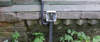
The metal of the connecting strip, located in the open air, to which the outlet to the main protective bus is connected, also needs to be painted.
Calculation rules
Grounding of electrical installations must be carried out after preliminary calculations. Planning allows you to establish the characteristics of the circuit, including its type, geometric shape, area, dimensions, number of electrodes and the distance between them. All of the above data, together with the earth’s current conductivity, have a direct impact on the overall resistance of the system.
The soil resistivity is of particular importance when carrying out calculations. Also, when making calculations, the seasonal factor is taken into account, making appropriate adjustments for this.
How to calculate a ground loop: step-by-step instructions
The project is created in several stages.
Step #1. Material selection
The metal and its profile are selected according to the above table 1.7.104. In production, they use those materials that are available or easiest to purchase in a particular area. The main condition is to comply with the required cross-section.
Step #2. Design Definition
Here we ask:
- driving depth of vertical grounding conductors H;
- the distance between them D;
- their number N.
The calculation assumes their arrangement in a line, and not in a triangle, when the shielding area increases. But if necessary, this option can be easily recalculated.
The direction of the line is selected taking into account local conditions so that it does not intersect with other highways, for example, sewerage, water supply, gas supply.
The driving depth is determined experimentally on one control specimen. A hole 0.7 meters deep is dug for it and a test rod is driven into it.
At the same time, the effort expended and the features of the technology are assessed. If you pour a bucket of water into the hole and let it soak into the soil for at least half an hour, then driving it in will require less physical effort.
The recommended length for a prototype is usually 2-2.5 meters. In short, rods are made only for very dense soils.
The distance between the vertical electrodes is chosen as a multiple of their length: this makes it possible to better take into account the coefficients of mutual influence.
The number of vertical grounding rods determines the length of the connecting strip, taking into account the section of the supply to the house, and its characteristics are also included in the design calculations.
When the configuration and dimensions are selected, then proceed to the next stage.
Step #3. Calculation of electrical resistance of the selected circuit
Calculations using mathematical formulas allow a preliminary assessment of the assembled structure. If it meets the standard, then you can begin to manufacture it. Otherwise, adjustments are made to the circuit by increasing the number of electrodes, deepening them, or increasing the distances.
First, the resistance of single grounding conductors is calculated, taking into account their shape and method of burial.
When the calculation is completed and verified, we begin to determine special utilization factors. They take into account the degree of shielding and mutual influence of the electrodes.
I present their most common part in a table.
After determining the influence coefficients, you can proceed to the general calculation of the resistance of the grounding device. I'll give you the formula.
The result obtained may fall within the standardized 30 ohms or be higher. If it does not meet the requirements of the PUE, then something will need to be added to the design or the dimensions changed. After this, you need to make a new calculation and achieve a positive result.
Calculations can be done manually using formulas on paper or use the online calculator attached below.
Having calculated several options for the design of the grounding structure, you will remember its features well and understand the assembly technology. And this will help to avoid mistakes and create a reliable device for long-term operation.
Sections of flexible copper grounding conductors of cable lines
| Cable core cross-section, mm2 | Cross-section of copper grounding conductor, mm2 |
| Up to 3x10 | 6 |
| 3×16 | 10 |
| 3×25 | 10 |
| 3×35 | 10 |
| 3×50 | 16 |
| 3×70 | 16 |
| 3×95 | 16 |
| 3×120 | 16 |
| 3×150 and above | 25 |
Grounding of wires with a metal sheath (SRG, TPRF, etc.) is also performed using flexible conductors by soldering. In this case, the grounding conductor is first wound on the wire in two or three turns for fastening.
8. Steel pipes used for grounding must have reliable connections. When the gasket is open, well-tightened red lead couplings with a lock nut on the side of the long thread section (squeeze) or other designs that provide reliable contact can be used. When laying hidden, only red lead couplings should be used, and they should additionally be welded on each side at one or two points.
If pipes are used for grounding, then even with open laying it is necessary to additionally weld the couplings to the pipes at one or two points.
9. Connections of neutral wires of overhead lines may be made using the same methods as phase ones (for example, compression).
Rules for portable installations
In some situations, it is possible to dispense with a local grounding system for electrical equipment equipped with autonomous power sources with a neutral that does not come into contact with the ground. Typically, portable grounding is used to protect installations that do not power other equipment. In this case, power supplies must have their own grounding conductors, and all elements of the installation must be connected to the housing of the power supply.
Grounding work for mobile electrical installations is carried out in accordance with voltage or resistance requirements. The resistance value should not exceed 25 ohms. Devices with autonomous power supplies and isolated neutrals are always monitored according to their insulation resistance level. In addition, it is necessary to ensure constant access to carry out insulation performance checks.
Portable grounding installations are installed during breaks in the operation of electrical equipment. Installation of protection begins only after the power supply is turned off. Grounding is installed on all disconnected phases. Moreover, the installation is carried out from all sides from where voltage is supplied.
Only specialists with an electrical safety group of at least fourth are allowed to install portable systems in electrical installations with voltages over 1000 volts. For installations with voltages less than 1000 volts, a third or higher electrical safety group is required.
Note! Elements not intended for this purpose cannot be used as grounding devices. Twists are also unacceptable.