Among the various possibilities for making your home safe, grounding in a private home occupies a special place: the electrical network diagram of any modern home will not be approved if it does not provide for a connection to a grounding loop.
Grounding diagram for a private house Source tirez.ru
There are several options and schemes for grounding a private house, plus clear requirements of the PUE (electrical installation rules) - all this must be known and understood in order for the electricity in the house to be safe.
Why do you need grounding in a private house: principle of operation
Grounding in a private home is considered an important part of the power supply system. It is installed for the following purposes:
- Protection of home inhabitants from electric shock (when touching a device with damaged electrical wiring insulation);
- Correct operation of modern electrical devices;
- Safe operation of gas equipment;
- Effective operation of lightning protection.
The principle of operation of the system is based on the elementary laws of physics, which say that electric current always moves in the direction of least resistance.
If the insulation of the device is damaged, the current flows out (short circuit) to the housing. This situation is fraught with malfunctions and breakdowns, not to mention the danger for a person to receive a sensitive discharge by accidentally touching the surface with his hand.
Let's talk about the circuit
The circuit is a complex, but quite understandable structure.
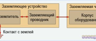
It consists of external and internal devices, which in turn are divided into:
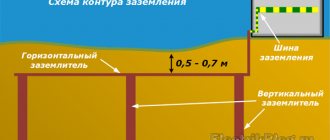
1. EXTERNAL DEVICES. Electrode stakes dug 2 meters deep, connected at the top by plates. A grounding conductor, which is round or flat steel, extends from the electrodes. The grounding conductor approaches the switchboard in the house and, as a rule, is connected to it through a copper wire.
2. INTERNAL DEVICES. Grounding wires that come from sockets, and directly the switchboard in which, using a special bus, the wires of the external and internal systems are combined.
Now let's look at how to install such grounding in your home yourself.
Video description
A succinct and clear grounding diagram for a private house, why it is needed and what it should be like, is shown in the following video:
If there is grounding, the current is distributed taking into account the resistance value of the body and the grounding loop of the house (in inverse proportion).
Carefully designed protective grounding creates an electrical circuit with a resistance significantly lower than that of the human body. The current passing through a person will not have a dangerous effect, and the main charge will go into the ground.
The passage of electric current through the human body in a system without grounding and with grounding Source plotnikov-pub.ru
The main element of grounding a private house is the grounding loop - the PUE defines it as metal conductors and grounding electrodes (rods or pipes) buried in the ground.
Internal electrical wiring according to modern standards is carried out with a three-wire wire (phase + neutral + ground). Protective grounding wires connect the circuit to electrical devices.
To ensure safety during thunderstorms, devices designed for this purpose are used - arresters designed for high currents and voltages.
Grounding calculator
In order to simplify the calculations, we suggest you use a simple and accurate grounding calculator.
Our online grounding calculator takes into account all correction factors and works based on the given formulas. In order to perform a reliable calculation, you need to fill out the program fields correctly.
- Soil . Select soil type to determine soil electrical resistivity.
- Climate coefficient. Adjustment in calculations based on climate zone:
- Zone I - from -20 to -15°C (January); from +16 to +18°С (July);
- Zone II - from -14 to -10°C (January); from +18 to +22°С (July);
- Zone III - from -10 to 0°C (January); from +22 to +24°С (July);
- Zone IV - from 0 to +5°C (January); from +24 to +26°С (July);
By clicking the “ Calculate ” button you will receive the following indicators:
- vertical grounding resistance;
- horizontal grounding resistance;
- general resistance to the flow of electric current.
The last parameter is decisive . According to PUE 7 “Rules for Electrical Installations” clause 1.7.101: the resistance of the ground electrode located in the immediate vicinity of the neutral of a generator or transformer or the output of a single-phase current source must be no more than 15, 30 and 60 Ohms, respectively, at line voltages 660V, 380V and 220V three-phase current source or 380V, 220V and 127V single-phase current source.
Video description
About the difference between TN and TT systems - in the video:
Decoding abbreviations
The first letter indicates the method of grounding the power source, the second characterizes the grounding of the consumer.
- T – source (consumer) is grounded;
- I – current-carrying parts of the source are isolated from the ground;
- N – the consumer is connected to the source grounding point (zeroed).
- C – conductors N (zero working) and PE (zero protective) are combined into one common conductor PEN;
- S – the functions of conductors N and PE are separated.
Subtypes of the TN system (TN-C, TN-S, TN-CS) differ in the method of connecting the N and PE conductors.
Grounding systems in alternating current networks Source zen.yandex.uz
TN-C system
In this case, one conductor (N and PE are combined throughout the entire electrical network) performs both operational and protective functions.
This method of organizing the system is ubiquitous in old housing stock; it is simple to implement and economical. But the absence of a separate protective grounding often leads to a short circuit during an emergency (power surges). According to modern standards, reflected in the requirements of the PUE, the TN-C grounding system is prohibited for new buildings. At the same time, there is no mandatory requirement to modernize old ones (unless major repairs are being done).
TN-S system
Here, the N and PE conductors are separated, and no voltage appears on the housings of electrical appliances. The system is safe and well protects people, household electrical equipment and the building. The main disadvantage is the high cost of arrangement.
TN-CS system
Combined system. At the output from the power source, conductors N and PE are combined in one conductor. A PE protective conductor is added at the entrance to the building.
When deciding which grounding is best for a private home, you should refer to the PUE code. He recommends the TN-CS subsystem as the main one for most consumers; it is simple to organize and more reliably protects against fire due to short circuit than others.
See also: Contacts of companies that provide electrical work services.
Differences between the TN-CS system Source keaz.ru
The procedure for carrying out installation work
To carry out installation work, it is necessary to prepare electrodes from a corner and a metal connection in the form of a steel strip.
If everything is ready, you can start marking. It is necessary to outline not only the future location of the main structure, but also the path along which the external circuit will be connected by a bus to the internal part of the system.
Then you need to:
- Dig a trench 50-70 cm deep along the markings.
- Drive the electrodes to the specified depth.
- Connect the tops of the pins with a metal bond using welding.
- Route the bus from the external circuit to the metering panel.
Next, the effectiveness of the assembled circuit is checked. Since self-installation implies the absence of specialized measuring equipment, you can use simple household methods.
When performing any electrical work, as well as during the final inspection, it is necessary to follow safety rules: use rubber gloves and shoes, do not work alone
One of these methods is to connect an ordinary incandescent lamp with a power of at least 100 W with one end to ground and the other to phase.
If the installation is done correctly, the lamp will burn as brightly as from a socket. Dim light or its complete absence is a reason to check the build quality.
Loop elements, grounding options and required materials
Protective grounding systems (grounding devices) are usually divided into the following elements:
- ground electrode (ground loop); there is a natural and artificial option;
- grounding conductors.
According to the PUE, it will be preferable to use a natural ground electrode (metal fence or pipeline) if its resistance meets the established standards. Otherwise, it is allowed to use an artificial ground electrode. For its construction you need:
- Metal for the ground electrode (pipe, smooth fittings, steel angle, rod, tape).
- A wire made of steel, copper or aluminum of sufficient cross-section.
- Fastening material (metal corners, clamps, couplings).
- Fastenings and insulation made of plastic.
What does modular-pin grounding consist of Source ecoask.ru
Modular-pin grounding
The grounding loop of a country house can be organized based on the modular-pin method. The system is extremely resistant to corrosion; no welding is used during installation. Pin grounding is assembled from steel rods up to 1.5 m long with a threaded connection. Copper-plated (or with a top layer of stainless steel) pins are driven into the ground with a vibrating hammer (perforator) with a special attachment. The electrodes (pins) are mounted at a great depth, so the circuit parameters do not depend on seasonal changes. The kit is usually purchased ready-made from the organization that handles the installation. The high cost of such a circuit is justified by its durability: the service life of copper-plated rods reaches 30 years, and of stainless steel – 50 years.
Modular grounding kit Source tirez.ru
Black metal outline
This design has a limited service life (5-10 years, due to corrosion); Over time, the circuit resistance deteriorates significantly. It is permissible to use black rolled metal with an anti-corrosion coating, but care must be taken that such a coating is not dielectric.
What is required for grounding
To independently arrange a grounding system for a country residential building, you will need the following tools and materials:
- bayonet shovel;
- sledgehammer;
- set of wrenches;
- welding machine;
- perforator;
- Bulgarian;
- corner 50x50 mm made of stainless steel (2 m long);
- copper wire with a cross section of 6 mm²;
- a stainless steel strip 4x40 mm (its length is equal to the distance from the porch of a residential building to the location of the ground loop);
- 3 metal strips (each length is 120 cm, minimum thickness is 4 mm, width is 4 cm);
- bolt M10 or M8.
It is not recommended to skimp on the thickness of the electrodes - the reliability and service life of the grounding structure depends on this.
Requirements for the resistance of the grounding device.
Grounding for a private home makes sense if the circuit resistance is minimal. In this case (when the human resistance is much greater than the resistance of the circuit), an imperceptible charge will pass through the body, and the remaining potential will go into the ground.
Resistance is determined by the type, quantity and depth of grounding elements, as well as the properties of the soil. Loamy and clayey soils with a moisture content of 20-40% are considered optimal.
To ensure that the grounding device is performing its functions, a resistance measurement is carried out.
Common mistakes, tips
When arranging grounding on their own, performers often make a number of typical mistakes. Among them:
- Applying paint to electrodes to prevent corrosion . This is prohibited, as the coating will prevent current from escaping into the soil.
- Connecting electrodes to metal bonding elements using bolts . Only welding is permissible, as it ensures durability and reliability of contact.
- Drilling holes for the pins, preventing them from fitting tightly to the soil , and thereby reducing the efficiency of the entire system.
To increase the durability of the system and maintain its performance characteristics, it is recommended to treat the metal elements of the ground loop with an anti-corrosion compound.
Particular care should be taken to impregnate welded seams.
What to do when replacing old TN-C ground wiring
Most of the older housing stock had a two-wire power supply system installed. Even if grounding was installed, it was carried out according to the TN-C scheme, which uses a single “neutral” conductor to perform two tasks - working (for the operation of electrical appliances and devices) and protective (for preserving electrical network equipment).
In essence, such a system reliably protects the electrical circuit as a whole, but leaves powered household electrical appliances and their owners practically without protection. In addition, in wet weather, such a connection can lead to voltage surges even during a protective shutdown - there have been cases of death for similar reasons.
PEN conductor separation diagram Source tirez.ru
When constructing new houses, this system is not allowed; where it has been preserved, it is recommended, if possible, to switch to the TN-CS system (at the entrance to the building, the PEN wire is re-grounded and subsequently divided into PE and N). In an emergency, conductor N is disconnected from the network, protecting household electrical appliances and their owners from problems.
The transition to a TN-CS system in houses with worn-out electrical wiring is justified for safety reasons.
Work progress
We dig trenches.
The depth of the trenches should be 0.5 - 0.7 meters. Their top view should represent an isosceles triangle with sides 1.2 meters long.
If necessary, a trench of the same depth is also dug to the place where the grounding plant is located in the house.
We hammer in the stakes.
We drive stakes into the corners of the trench to a depth of 2 meters. We leave 20 - 30 cm for welding other structural elements.
Don’t forget to sharpen the stakes; for example, if you have a corner, you can do this with a grinder.
While driving the stakes from above, you can water them with water, which will act as a kind of lubricant. This way the work will go faster, and the sledgehammer will be easier to use.
Welding work.
We weld horizontal steel strips to the stakes. Separately, we weld a metal plate going to the grounding entry point into the house.
Connection to the ground bus.
Using a copper wire with a diameter of 6 mm and bolts, we connect one end of the wire to the metal plate and the other to the busbar.
Why do you need an RCD if there is grounding?
An RCD (residual current device) is a high-speed switch that works in tandem with a ground loop and responds to current leakage by breaking the circuit.
Operating principle of RCD Source tirez.ru
Circuit without grounding and RCD
When the insulation of a conductor is broken, a phase appears on the metal body of the electrical device. If the current has nowhere to go further, then when a person comes into contact with the body of an electrical device, the discharge will go through the body. The consequences will depend on many factors and the results can be different - from fear to interruptions in heart function.
Without grounding, the phase on the surface of the device with damaged wiring will remain until the input circuit breaker turns off .
RCD in a circuit without a protective conductor (TN-C)
In such a system, if the conductor insulation is broken, the RCD will not immediately operate, since no leakage current will occur. But as soon as a person touches the damaged device, part of the current will go into the body and the RCD will trip.
Even without grounding, current will flow through the human body only for the time required for the RCD to trip - usually tenths of a second. As a result, painful sensations are possible, but a fatal outcome can most likely be avoided.
Circuit with protective conductor (TN-S and TN-CS) and RCD
If an electrical appliance is in contact with the ground loop and is connected through an RCD, then if the phase conductor shorts to the metal body of the electrical appliance, leak immediately appears (which goes into the ground). The RCD trips and breaks the circuit.
Gas boiler and RCD
First of all, you need to understand that grounding a gas boiler in a private house must be carried out without fail - there are no exceptions.
Grounding the gas boiler and installing the RCD are carried out simultaneously. This is a necessary condition when connecting gas to a residential building, since surface tension forms on the body of the gas boiler during operation.
Grounding a gas boiler in a private home will avoid damage to expensive electronic equipment and prevent fire caused by static electricity. This measure, given the high explosiveness of the gas, serves as additional protection against fire.
All parts of a gas boiler must be grounded Source pinterest.com
So which circuit should you choose?
Let's first figure out under what conditions certain types of circuits are used.
Closed triangular outline:
- The 220/380V network is brought into the house through a power input panel.
- Continuous total power consumption is more than 3 kW.
- Availability of industrial-type electrical appliances with a provided grounding connection (lathe, circular saw, drilling machine, etc.).
Two groups of linear grounding conductors:
- The total power consumption is over 1 kW for 20 minutes.
- The electrical wire is routed underground through an external panel.
- The house has at least one of the communications (communications, gas, water, sewerage).
There are many other factors, so in this case it is best to consult a specialist and do the work yourself.
What kind of work is done when installing grounding?
The entire process of creating a grounding loop is divided into the following stages:
- After determining the safe depth of the structure (where the soil is always wet), a trench is dug.
- Metal rods (grounding electrodes) are buried in the ground.
- A grounding loop is assembled: rods arranged in a row or in the shape of a figure (usually a triangle), connected with tape or pipes, and welded in series.
- The circuit is additionally welded to the down conductor with steel tape.
- The finished ground electrode is connected to the electrical panel, and the trench is backfilled.
During installation, competent specialists take into account some important nuances:
- The contour should be located below the soil freezing line. Otherwise, when the water in the ground turns to ice, the ground will stop conducting current and grounding will not work.
- Grounding electrodes cannot be painted, since the paint layer is a dielectric and there will be no contact of the circuit with the ground.
Grounding in a private house, circuit diagram Source asutpp.ru
How to make grounding yourself
Before you independently arrange the grounding of your country house, it is recommended to study the step-by-step instructions on how to properly make and install the structure.
Selecting a location for installing circuits
First of all, a safe location for the ground loop is selected on the site for the residents of the cottage. If the electrical wiring breaks down, the protection is triggered, and all the current goes to the electrodes buried in the ground. It is very dangerous to be here at this moment.
Therefore, the site for laying the system is selected where no one walks. It is better to make a branch behind the building near the fence, but the distance from the ground electrode to the foundation of the house should not exceed 1 m. It is additionally recommended to fence off the danger zone with a small wooden fence.
Initial excavation work
In the selected area, mark a triangle with equal sides of 3 m each and remove the soil to a depth of 0.5 m. The width is equal to the size of a bayonet shovel. This is done to facilitate welding of the metal strip with the pins.
A trench of similar depth is dug from the triangle to the foundation of a residential building. It contains a terminal for the current that connects the electrical panel to the ground loop.
Installation of ground electrodes
A grounding structure is laid in the finished trench. To do this, the ends of the pins are first sharpened with a grinder, then driven into the ground to a depth of 3 m at the ends of the triangle. Their upper ends should be located on the plane of the pit.
Welding
Metal strips 4 mm thick and 40 mm wide are welded to the protruding ends of the electrodes driven into the ground. The result is a steel triangle, to which a long strip of steel is welded, extending to the foundation of a residential building. Here the grounding structure is connected to the conductors exiting the panel. To do this, an M8 (M10) bolt is welded to the end of the strip at a distance of 0.3-1 m from the ground surface.
backfilling
After completing the welding work, the trench is filled with soil and thoroughly compacted. But first, a saline solution is poured into the bottom of the pit. To prepare it, use a bucket of water and 2-3 packs of salt.
Test work for functionality
After installation work is completed, a mandatory check is carried out. To do this, a light bulb is connected to one end of the circuit. The contour is made correctly if the lamp shines brightly. The performance is also checked using a factory device - a multimeter.
Checking the grounding functionality
Related article:
How to use a multimeter correctly. In a separate review, we will tell you how to correctly measure basic electrical characteristics in the most common situations. Read!
Components of the system
Grounding installation
The key parameter of this system is the grounding resistance. The grounding resistance must be so small that the current flows along this path in the event of an emergency. This will provide protection if a person accidentally touches the surface to which voltage is applied.
Experts recommend connecting household appliances to a grounding system
To obtain the required result, the chassis and housing of household appliances at home are connected to the main bus of the grounding device, creating an internal circuit. Metal elements of the building structure and water supply pipes are also connected to it. The composition of such a potential equalization system is described in detail in the PUE (clause 1.7.82). Another part of the protection, the outer contour, is installed outside the building. It is also connected to the main bus. To equip a private house, you can use different schemes. But the easiest way is to bury metal rods in the ground.
The following list shows the individual system components and their requirements:
- Wires that connect irons, washing machines and other end consumers. They are located inside the network cable, so you only need to have an appropriate ground line connected to the outlet. In some situations, when installing hobs, ovens, and other equipment built into furniture, it is necessary to connect the housings with a separate wire.
- As a common bus, you can use not only a special wire, but also “natural” conductors such as metal frames of buildings. Exceptions and exact rules will be discussed below. It should be noted here that this section of current passage must be created in such a way as to prevent mechanical damage during operation.
- The outer contour of a private house is created from metal elements without insulation. This increases the likelihood of destruction by the corrosion process. To reduce this negative impact, non-ferrous metals are used. The places of welded joints of steel parts are covered with bitumen mixtures and other compositions for similar purposes.
- The actual resistance of this type of grounding device will depend on the characteristics of the soil. Clay and shale retain moisture well, but sand does not. In rocky soils, the resistance is too high, so you will need to look for another place for installation, or immerse the ground electrode even deeper. During particularly dry periods, regular watering of the soil is recommended to maintain the functionality of the device.
Soils have different conductivities
Why comply with the requirements?
It may seem that strict compliance with the Rules is redundant; it is only necessary to pass official checks and put the property into operation. Of course this is not true.
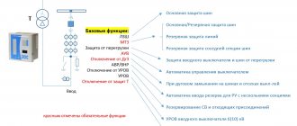
The standards are created on the basis of scientific knowledge and practical experience . The PUE contains the following information:
- Formulas for calculating individual parameters of the protective system.
- Tables with coefficients that help take into account the electrical characteristics of different conductors.
- Procedure for testing and inspection.
- Specialized organizational events.
The practical application of these standards will prevent electric shock to people and animals. The creation of the contour must be flawless, in strict accordance with the Rules. This will reduce the likelihood of fires during accidents and will help eliminate the development of negative processes that can cause damage to property.
This article discusses issues of protecting a private home. Thus, those sections of the PUE that relate to working with voltages up to 1,000 V will be studied.
Checking correct installation
Upon completion of the work, be sure to measure the resistance of the installed grounding.
The circuit resistance should be:
- for a network voltage of 380V – 2 Ohm;
- for a 220V network – 4 Ohms.
To carry out measurements, it is recommended to use a multimeter, the cost of which is quite high, but you can go the other way.
Checking grounding with a multimeter
Performance can be easily checked using a lamp with a power of more than 100W. To do this, you need to connect the lamp with one contact to the phase and the other to the ground loop. The bright light of the lamp indicates correct installation, while dim lighting indicates too weak contact between the circuit elements and the need to take a more responsible approach to connecting the joints.
Checking with a lamp
The complete absence of light from the lamp indicates the presence of an error, which may require a complete check of the entire system to eliminate it.