Among the various possibilities for making your home safe, grounding in a private home occupies a special place: the electrical network diagram of any modern home will not be approved if it does not provide for a connection to a grounding loop.
Grounding diagram for a private house Source tirez.ru
There are several options and schemes for grounding a private house, plus clear requirements of the PUE (electrical installation rules) - all this must be known and understood in order for the electricity in the house to be safe.
Why do you need grounding at all?
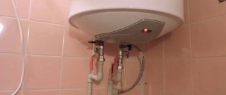
The main role of grounding is safety. Building an effective system of protection against electric shock is impossible without a grounding system. Even the grounding of the metal frame itself reduces the touch voltage when the insulation inside the equipment is broken. And for greater reliability, a residual current device (the so-called RCD) is used, which turns off electrical appliances when the insulation is broken and dangerous voltage occurs on their housings. And the efficiency of the RCD largely depends on the quality of the grounding system. I tried to describe how to do this and how it all works in this article.
Video description
A succinct and clear grounding diagram for a private house, why it is needed and what it should be like, is shown in the following video:
If there is grounding, the current is distributed taking into account the resistance value of the body and the grounding loop of the house (in inverse proportion).
Carefully designed protective grounding creates an electrical circuit with a resistance significantly lower than that of the human body. The current passing through a person will not have a dangerous effect, and the main charge will go into the ground.
The passage of electric current through the human body in a system without grounding and with grounding Source plotnikov-pub.ru
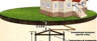
The main element of grounding a private house is the grounding loop - the PUE defines it as metal conductors and grounding electrodes (rods or pipes) buried in the ground.
Internal electrical wiring according to modern standards is carried out with a three-wire wire (phase + neutral + ground). Protective grounding wires connect the circuit to electrical devices.
To ensure safety during thunderstorms, devices designed for this purpose are used - arresters designed for high currents and voltages.
TN-CS system
In the TN-CS PEN wire passes from the solidly grounded neutral of the substation to the entrance to the building , combining the functions of the neutral ( N ) and protective ( PE ) wires. , it splits into two wires: PE and N. The first of them plays the role of a protective (grounding) wire, the second - a working neutral wire.
TT system
In the TT , everything is the same, but the neutral wire coming from the solidly grounded neutral of the substation does not take on the protective function, but only plays the role of the neutral working wire N. PE wire (bus) is organized separately, using an autonomous ground electrode and is not connected to N anywhere.
Deepening the electrodes
The electrodes are driven into the ground by driving them with a sledgehammer. To make work easier, it is better to use a scaffold or stepladder. If the metal of the electrodes is too soft, then the blows are delivered through special wooden bars. There is no need to drive the pins in completely: about 10-20 centimeters should remain above the ground, which are used to connect to the circuit.
The factory electrodes are driven in with a jackhammer. After the pin is deepened, a coupling and an additional grounding conductor are screwed onto it. The process is repeated several times until the required depth is achieved.
Why does the PUE recommend the TN-CS system?
So why does the PUE the TN-CS grounding system as the main system in our power networks? After all, this system has a very significant drawback: in the event of a break or burnout of the neutral wire along the path from the substation to the consumer, all housings and metal structures connected to the PE immediately find themselves under dangerous voltage relative to the ground. And anyone who touches them risks receiving a life-threatening electric shock.
But there is a big advantage: if the insulation is damaged or some other situation leading to a short circuit of the phase wire to the housing, a situation similar to a short circuit occurs. As a result, a large current arises, causing the circuit breaker to trip. TT system , so short-circuit protection will not always work. Why does this happen? Because the current does not flow through the PEN wire, as in the previous case, but through the ground. Let's imagine that the resistance of the ground electrode is 4 ohms, plus the resistance of the ground electrode at the substation is also not zero. In such a situation, the current strength will be no more than 50A, to which even a 10-amp category C circuit breaker will not respond (in fairness, it must be said that it will still work, but not due to cutoff, but due to overload, after some time). But, if we take the private sector, then often the grounding resistance there is not 4 Ohms, but much higher, and the ground fault currents are much less.
Which is better - homemade contours or a purchased kit?
To equip the grounding of a country house, you can buy a ready-made device kit. This will allow you to quickly install the structure, often without even the use of welding equipment. To connect individual elements, manufacturers make special fasteners.
Factory designs are considered more reliable because... All parts are made of stainless metal and are additionally treated with protective compounds. But they are expensive - from 7,000 to 10,000 rubles.
A grounding system assembled with your own hands from materials available at home allows the owners of a private cottage to save a lot of money. And if you correctly calculate the circuit and carry out the installation work efficiently, the homemade design will last no less than the factory one.
Why do you need an RCD?
Fortunately, there are devices such as RCDs that respond to even small (tens of milliamperes) ground leakage currents, so they are mandatory in TT . For proper operation of an RCD at a nominal value of 300 mA, the grounding resistance must be at least 4 Ohms, for 100 mA - 14 Ohms, 30 mA - 47 Ohms.
What happens when the protective device does not work? If this is a machine in the TN-CS system , then a large short circuit current can cause melting of the wires and a fire. If the RCD in the TT system , then there will be life-threatening voltage on the housings of electrical appliances. Therefore, my advice to you: approach the selection of protection devices with the utmost responsibility, periodically check their performance during operation, and use duplication if possible. For example, in addition to the general one, install additional RCDs or difautomatic devices , at least on those lines where there is the greatest danger (bathroom, kitchen, etc.). In general, if I were to develop the rules, I would introduce mandatory two-stage differential protection.
Now to the question of whether it is worth installing an RCD in the TN-CS system . Definitely worth it. Of course, it will not save you from the breakage of the neutral wire described above, but if there is a current leak to the ground, it will work and prevent further development of the malfunction at an early stage, when its value is not enough to trigger the machine.
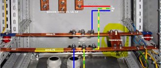
Main ground bus
According to clause 1.7.121 of the PUE, the following can be used as PE conductors in electrical installations with voltage up to 1 kV:
- specially provided conductors:
- cores of multi-core cables;
- insulated or non-insulated wires in a common sheath with phase wires;
- permanently laid insulated or non-insulated conductors;
- exposed conductive parts of electrical installations:
- aluminum cable sheaths;
- steel pipes for electrical wiring;
- metal shells and supporting structures of busbars and complete devices of factory production (provided that the design of the boxes and trays provides for such use, as indicated in the manufacturer’s documentation, and their location excludes the possibility of mechanical damage);
- Some third party conductive parts:
- metal building structures of buildings and structures (trusses, columns, etc.);
- reinforcement of reinforced concrete building structures, subject to the requirements of 1.7.122;
- metal structures for industrial purposes (crane rails, galleries, platforms, elevator shafts, lifts, elevators, channel frames, etc.).
P. 1.7.122. The use of exposed and third-party conductive parts as PE conductors is permitted if they meet the requirements of this chapter for conductivity and continuity of the electrical circuit.
More details
Third-party conductive parts can be used as PE conductors if they also simultaneously meet the following requirements:
- the continuity of the electrical circuit is ensured either by their design or by appropriate connections protected from mechanical, chemical and other damage;
- their dismantling is impossible unless measures are taken to maintain the continuity of the circuit and its conductivity.
The following are not allowed to be used as PE conductors:
- metal shells of insulating tubes and tubular wires, supporting cables for cable wiring, metal hoses, as well as lead sheaths of wires and cables;
- gas supply pipelines and other pipelines of flammable and explosive substances and mixtures, sewerage and central heating pipes;
- water pipes with insulating inserts.
Neutral protective conductors of circuits are not allowed to be used as neutral protective conductors of electrical equipment powered by other circuits, and also to use open conductive parts of electrical equipment as neutral protective conductors for other electrical equipment, with the exception of shells and supporting structures of busbars and complete factory-made devices that provide the possibility connecting protective conductors to them in the right place.
The use of specially designed protective conductors for other purposes is not permitted.
The main grounding bus can be made inside the input device of an electrical installation with voltage up to 1 kV or separately from it (clause 1.7.119. PUE).
Inside the input device, a PE bus should be used as the main grounding bus.
When installed separately, the main grounding bus must be located in an accessible, convenient place for maintenance near the input device.
The cross-section of a separately installed main grounding bus must be no less than the cross-section of the PE (PEN) conductor of the supply line.
The main grounding bus should, as a rule, be copper. It is allowed to use a main grounding bus made of steel. The use of aluminum tires is not permitted.
The design of the bus must provide for the possibility of individual disconnection of the conductors connected to it. Disconnection must only be possible using a tool.
Third-party conductive parts may be used to connect multiple main ground bars if they meet the electrical continuity and conductivity requirements of 1.7.122.
Measures to prevent destruction of PEN
What measures does the PUE to prevent the destruction of PEN ? First of all, mechanical protection must be provided, and if a break cannot be avoided, then it must be not the neutral wire, but the entire cable. That is, if this is an overhead line, then conduct it with a multi-core SIP ; separate wires on supports are not suitable for TN-CS . Because the bucket will hook an excavator or dump truck with the body, and the neutral wire usually goes to the bottom and gets caught much more often, and a tree can also fall, a tractor can drive into a pole, strong wind, icing... - and then the consequences that we have already mentioned above. In addition to strengthening and combining into a common sheath, the neutral wire is periodically re-grounded, every 200 meters for areas with low lightning activity, and every 100 meters for areas with more than 40 thunderstorm hours per year. And yet, when using TN-CS, a mandatory condition is a potential equalization system ( PSUP, DSUP ). This means that everything metal (pipes, fittings, bathtub, etc.) is connected to a PE . And even in the event of a zero break, all metal structures in the house will have, albeit different from the ground, but the same potential everywhere. And in private houses that have a garden, outbuildings, etc., it is often a SUP , then you should definitely do TT .
Do I need my own grounding when connecting to the TN-CS ? It won't be redundant. Moreover, the better the grounding, the greater the current that can flow through it. This must be taken into account when choosing the cross-section of the wire from the shield to the ground electrode, as well as from the support to the shield (which, by the way, for any allocated power cannot be less than 16 sq. mm).
What kind of work is done when installing grounding?
The entire process of creating a grounding loop is divided into the following stages:
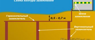
- After determining the safe depth of the structure (where the soil is always wet), a trench is dug.
- Metal rods (grounding electrodes) are buried in the ground.
- A grounding loop is assembled: rods arranged in a row or in the shape of a figure (usually a triangle), connected with tape or pipes, and welded in series.
- The circuit is additionally welded to the down conductor with steel tape.
- The finished ground electrode is connected to the electrical panel, and the trench is backfilled.
During installation, competent specialists take into account some important nuances:
- The contour should be located below the soil freezing line. Otherwise, when the water in the ground turns to ice, the ground will stop conducting current and grounding will not work.
- Grounding electrodes cannot be painted, since the paint layer is a dielectric and there will be no contact of the circuit with the ground.
Grounding in a private house, circuit diagram Source asutpp.ru
What is the potential equalization system used for?
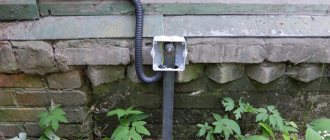
Now about the SUP - potential equalization system. Various utilities are connected to the house: water supply, gas, sewerage, etc. In the event of a malfunction in the electrical network (at least the same notorious zero burnout or, for example, an insulation breakdown on the body of an electrical appliance), a dangerous potential difference (i.e. voltage) may appear between the PE bus (i.e., the housings of electrical appliances) and pipes or other metal structures that come into contact with them. To prevent this from happening, all stationary metal structures (pipes, fittings, bathtubs, sinks, trays, door frames, etc.) are connected to the grounding system with wires of sufficient cross-section. At the same time, before grounding a gas pipe, a number of requirements must be met and agreed upon with the relevant service.
In addition to the SUP , the concept of DSUP - an additional potential equalization system. This applies to bathrooms and other rooms where water and electricity are adjacent. That is, in a room with high humidity, a box with a terminal block is placed, called a potential equalization box ( PEC ), from which grounding conductors are routed to all metal structures. By the way, if the pipes are plastic, then special metal inserts are made, which are also connected to the DSUP . Also, if there is an electrical heating system in the floor or electrical wiring is running, then a mesh of reinforcement is laid between them and the floor covering, which is also connected to the DFCS . There are a great variety of devices for connecting grounding to something, for all cases, some of them are shown in the photo below for convincing:
By the way, you cannot use EMS in a single apartment in an apartment building. This is fraught with serious consequences. In general, this article was written mainly for owners of private houses who have to take care of electrical safety on their own. Apartments are a separate issue; a lot here depends on when the house was built, when it was majorly renovated, and what kind of electrical wiring system is in the house. Of course, it is impossible to cover all the nuances of such a complex issue in one article, so always consult with a specialist on site, and entrust such work only to qualified workers. For your life and those around you depend on it.
Electrode connection
The pins are connected to each other by a strip of 40x4 millimeters. Rolled ferrous metal is welded because the bolts quickly corrode, which leads to an increase in the resistance of the overall circuit. Welding seams must be of high quality.
From the assembled circuit, grounding is carried out in a strip to the house and attached to the foundation. The wire from the shield is connected to a bolt welded to the edge of the strip.
The fastening clamp is installed on the last electrode, after which the wire is secured. The clamp is sealed with a special tape.
Your own grounding in the private sector
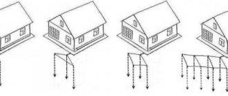
Now about the ground electrodes themselves. They are usually made from steel rods (angles, fittings, pipes), which are driven into the ground as deep as possible. There are often recommendations to make grounding from three pins driven vertically, arranged in an equilateral triangle and connected by welding with a metal strip or fittings. In this case, you need to know that the closer the electrodes are located to each other, the lower their total efficiency. If these same three electrodes are placed along the same line, it will not be worse at all, and even a little better. The effectiveness of grounding conductors is determined by the resistance to spreading, which is measured using special instruments using a specific method. The lower this resistance, the better. On the Internet - on blogs, forums and even on corporate websites you can often find simplified methods for measuring grounding resistance. Many of them are frankly amateurish or very inaccurate. In one of the following articles I will go into detail about this and explain everything in detail. For now, just trust the professionals.
Typically, the upper layers of soil have a higher resistivity than the lower ones, so they try to drive the ground electrodes into the ground as deep as possible. To mechanize this process, you can use pneumatic and electric vibratory hammers or jackhammers with special tips. It often happens that three pins are not enough, then they make more. The distance between the pins should be large enough, preferably twice as large as their length. But you can get by with a single ground electrode if you drive it very deep. This design is called a deep-modular grounding system. You can see how this is done in the video below.
Copper
Along with galvanized strips, grounding strips with copper coating are widely used in practice. Copper is less electrochemically active than steel and zinc. Therefore, it lasts longer and can be used in more difficult conditions.
Copper-bonded grounding conductors have good ductility. They are supplied in unmeasured lengths, which is convenient for laying grounding loops. Copper strip is also used for the internal circuit as a main conductor used to connect equipment to it. The disadvantage of copper-plated grounding strips is their high price.
How to make grounding - video
Below is a more budget-friendly option for installing grounding. Here the grounding electrodes are connected to each other without threads. According to manufacturers, a strong connection is achieved by flattening the lower end of the pin in the socket. Of course, this raises questions about how reliable and durable such contact is, but the video is quite convincing.
And for those who like conservative approaches, we suggest getting acquainted with the traditional method of constructing a grounding device, using several electrodes connected to each other by welding. Instead of the reinforcement bars recommended in this video, if they are unavailable, you can use other types of rolled metal: angles, pipes, etc. It is better to take longer electrodes; the longer they are, the better the grounding will be.
Grounding switches
1.7.109. The following can be used as natural grounding electrodes:
1) metal and reinforced concrete structures of buildings and structures that are in contact with the ground, including reinforced concrete foundations of buildings and structures that have protective waterproofing coatings in non-aggressive, slightly aggressive and moderately aggressive environments;
2) metal water pipes laid in the ground;
3) casing pipes of boreholes;
4) metal sheet piles of hydraulic structures, water conduits, embedded parts of valves, etc.;
5) rail tracks of main non-electrified roads and railways and access roads in the presence of a deliberate arrangement of jumpers between the rails;
6) other metal structures of structures located in the ground;
7) metal shells of armored cables laid in the ground. Cable sheaths can serve as the only grounding conductors when there are at least two cables. Aluminum cable sheaths are not allowed to be used as grounding conductors.
1.7.110. It is not allowed to use pipelines of flammable liquids, flammable or explosive gases and mixtures, and sewerage and central heating pipelines as grounding conductors. The specified restrictions do not exclude the need to connect such pipelines to a grounding device for the purpose of equalizing potentials in accordance with 1.7.82.
Reinforced concrete structures of buildings and structures with prestressed reinforcement should not be used as grounding conductors, however, this restriction does not apply to overhead line supports and outdoor switchgear support structures.
The possibility of using natural grounding conductors based on the density of currents flowing through them, the need for welding reinforcing bars of reinforced concrete foundations and structures, welding anchor bolts of steel columns to reinforcing bars of reinforced concrete foundations, as well as the possibility of using foundations in highly aggressive environments must be determined by calculation.
1.7.111. Artificial grounding conductors can be made of black or galvanized steel or copper.
Artificial grounding conductors should not be painted.
The material and smallest dimensions of grounding conductors must correspond to those given in Table 1.7.4.
1.7.112. The cross-section of horizontal grounding conductors for electrical installations with voltages above 1 kV should be selected according to the condition of thermal resistance at a permissible heating temperature of 400 °C (short-term heating corresponding to the duration of the protection and tripping of the circuit breaker).
If there is a risk of corrosion of grounding devices, one of the following measures should be taken:
increase the cross-sections of grounding conductors and grounding conductors, taking into account their estimated service life;
use galvanized or copper grounding conductors and grounding conductors.
In this case, one should take into account the possible increase in the resistance of grounding devices due to corrosion.
Trenches for horizontal grounding conductors must be filled with homogeneous soil that does not contain crushed stone and construction waste.
Grounding electrodes should not be located (used) in places where the ground is dried out by the heat of pipelines, etc.
How to measure the resistance of a grounding device
There are many misconceptions about this, wandering from one site to another, and transmitted from one under-electrician to another. Here is a typical example, with which I categorically disagree, taken by the way from one of the top sites (link):
I don’t even know whether to laugh or cry here. Not only are the potential and current measuring probes here connected to each other by a cable, but it is also proposed to use a megohmmeter for measurements (!). Ostensibly in order to apply a sufficiently high voltage to the electrodes. Yes, when measuring high resistances, these devices produce hundreds and even thousands of volts. But, if such a device has a measuring range that allows you to measure units of Ohms, then there will not be any hundreds of Volts there. In general, nothing good will come from such measurements. In fact, a certain quantity will be measured, including the resistance of the wires and the spreading resistance of the grounding device and the measuring electrodes. Well, if the resistance of the wires connecting the device to the electrodes can somehow be neglected, then the electrode-ground resistance is usually much higher than the ground-ground resistance, which makes the error much larger than the measured value itself.
By the way, even in Wikipedia itself there are big mistakes associated with a misunderstanding of the process of spreading currents in the ground and the concept of grounding resistance. I will write about this below, but first a little about how to do it correctly. Firstly, there is no need to invent anything, but use instruments and techniques specially developed for this. It is described competently and sensibly here and looks something like this:
There is a completely legitimate way to measure the resistance to spreading without a special device. To do this, we will need a 220/12 or 220/6 step-down transformer with a power of 250 W or higher. A welding transformer is also perfect for this. In addition to the transformer, you also need an ammeter and a voltmeter, the ratings of which any electrician can calculate based on the voltage value and the expected resistance. The distances between ground electrode G and potential electrode P, as well as between P and current electrode T are usually taken to be about 20 meters. Sometimes, to limit the current, a ballast resistor is connected in series with the primary or secondary winding (not shown in the diagram):
And finally, for advanced readers, about the Wikipedia jamb. There is a page there https://ru.wikipedia.org/wiki/Grounding. And here there is such a masterpiece:
Since the resistance of the ground loop of the local charger is taken to calculate the parameters of the consumer's electrical installation (to reduce the likelihood of creating a dangerous step voltage on the consumer's territory, the minimum possible numerical value is usually required), the soil resistance between the transformer supplying consumers and the local charger of the consumer - the result of the resistance of the local The memory of an individual consumer is taken only for an individual consumer, and not for the entire electrical network. In other words: since the open metal parts of an individual consumer are not directly connected to the transformer (but only through the main grounding bus), then in the event of a break in the PEN conductor between the consumer's charger and the transformer substation's charger, a huge electrical resistance is formed through the soil between them , which, by law, Ohm does not allow large currents to flow through the charger of an individual consumer.
I have highlighted the places of interest. In fact, the soil does not have any “huge resistance”. The entire planet is at the disposal of the current flowing in the earth. And its resistance is so small that it cannot in any way affect the magnitude of this current. In this case, what matters is only the transition resistance between the grounding device and the soil, and the resistivity of the soil in the immediate vicinity of the grounding device. This is what we call the current flow resistance of the grounding device or, in short, the grounding resistance. Yes, of course, the resistance of the neutral wire between the substation and the consumer is usually much less than the sum of the spreading resistances of the grounding conductors of the substation and the consumer. But even this resistance of several Ohms or tens of Ohms is somehow difficult to call huge. So it turns out that even authorities cannot always be trusted. Trust but check. And if suddenly your doubts cannot be resolved, welcome to our forum of electricians , we will solve the issue collectively.
Types of material (profiles)
According to the requirements of the PUE, which contain instructions on what the resistance of current flow in the ground should be, in most cases this indicator is set at a level of no more than 4 ohms. To obtain this value, you usually have to make a lot of effort to adhere to the same technology requirements.
First of all, this concerns the materials used in assembling the grounding loop, selected based on the following conditions:
- When choosing pins, preference should be given to ferrous metal blanks;
- The most commonly used rod is a standard size of 16-20 mm or a corner with parameters 50x50x5 mm and a metal thickness of about 5 mm;
- It is not allowed to use reinforcement as circuit elements, since it has a hardened surface that affects the normal flow of current;
- For these purposes, it is pure rod that is suitable, and not its reinforcement substitute.
Note! For areas with dry summers, thick-walled metal pipes are best suited, the lower end of which is flattened into a cone, and then several holes are drilled in this part of the pipe. According to the provisions of the PUE, before placing them in the ground, holes of the required length are first drilled, since driving them manually is quite problematic
In the case of a particularly dry summer and a sharp deterioration in the parameters of the ground electrode, a concentrated saline solution is poured into the hollow parts of the pipes, which makes it possible to obtain the resistance that should be in accordance with the requirements of the PUE. The length of pipe blanks is selected within 2.5-3 meters, which is quite enough for most Russian regions
According to the provisions of the PUE, before placing them in the ground, holes of the required length are first drilled, since driving them in manually is quite problematic. In the case of a particularly dry summer and a sharp deterioration in the parameters of the ground electrode, a concentrated saline solution is poured into the hollow parts of the pipes, which makes it possible to obtain the resistance that should be in accordance with the requirements of the PUE. The length of pipe blanks is selected within 2.5-3 meters, which is quite enough for most Russian regions.
This type of profile blanks has special requirements regarding the order of their placement in the soil and consists of the following:
- Firstly, the pipe elements of the protective circuit must be placed at a depth exceeding the soil freezing level by at least 80-100 cm;
- Secondly, in particularly dry areas, approximately a third of the length of the ground electrode should reach wet soil layers;
- Thirdly, when fulfilling the second condition, one should focus on the peculiarities of the location of the so-called “groundwater” in a given region. If they are located at a significant depth, according to the rule formulated in the provisions of the PUE, it will be necessary to prepare longer pipe sections.
The type and profile of the pin blanks used in the construction of the grounding switch can be found in the figure below.
In practice, in most regions of Russia, a steel corner and a strip of the same metal are usually used. In order to obtain more accurate parameters of the grounding elements used, geological survey data will be required. If this information is available, it will be possible to involve specialists in calculating the parameters of the ground electrode.
How to calculate grounding
Grounding resistance greatly depends on the soil in which it is located. Moreover, a ground electrode driven into the ground is often located simultaneously in different layers of soil, which have different resistivities, which complicates the calculation and results in rather approximate results. Nevertheless, such calculations exist, and they are mandatory for most industrial facilities. In the private sector, a certain minimal design is usually made, the resistance is measured, and then it is strengthened as necessary (the ground electrode is driven deeper, or new ground electrodes are added). Below is the formula for calculating a single vertical ground electrode in homogeneous soil:
R=(ρ/2πL)(ln(2L/d)+0.5ln((4T+L)/(4T-L)))
ρeq - soil resistivity, Ohm*m
L is the length of the rod in meters
d—diameter of the rod in millimeters
T — distance from the ground surface to the middle of the rod, m
Soil resistivity
| Peat | 20 |
| Soil (chernozem, etc.) | 50 |
| Clay | 60 |
| Sandy loam | 150 |
| Sand with groundwater up to 5 m | 500 |
| Sand with groundwater deeper than 5 m | 1000 |
Galvanized
To extend the service life and protect from environmental influences, a zinc coating is applied to the steel in accordance with GOST 9.307-89 “Hot zinc coatings”. The steel strip is pre-treated and immersed in a container with molten zinc. The coating thickness is 40-200 microns. The thicker the layer, the more it contributes to increasing the strength of the product. The coating is strengthened by repeated immersion of the strip in molten zinc.
Galvanization is currently the most effective and cheapest method of protection. Coating increases the cost of rental, but its service life increases. The properties of zinc are preserved even with minor surface damage. The galvanized strip is resistant to corrosion, elastic, does not crack and has a neat appearance. It is produced from carbon and low-alloy steel grades by slitting steel sheets and is supplied in the form of coils weighing 50-60 kg or rods 5-6 m long.
According to the PUE, the minimum cross-section of the grounding conductor for installations with voltages less than 1 kV is 75 mm2. 4x20 mm strip is the most economical solution that meets these requirements. More often, a galvanized strip with a cross section of 4x40 mm, 5x40 mm, 5x50 mm is used to make a grounding loop. These products ensure compliance with standards and are convenient for grounding installation. According to the standard, one meter of 4x40 mm strip weighs about 1.3 kg. The weight of a linear meter is also regulated by GOST 103-2006 and is used to calculate the required amount of tape.
How to effectively distribute electrodes
When creating a multi-rod grounding system, it is necessary to remember that the connecting strip (pipe, fittings, corner, etc.) between the electrodes, if it is in the ground, is also an additional grounding conductor and reduces the overall resistance. Also, the effectiveness of additional electrodes decreases as the distance between them decreases. Therefore, if we want to achieve minimal resistance, we need to place the ground electrodes further away from each other. But besides resistance, there are other things to pay attention to. If lightning rods are connected to our grounding conductors, then they should not be taken outside the protected object. For example, if we are building a circuit of 4 vertical ground electrodes for a square house, then it would be reasonable to place them near each corner. If the object is narrow and long, then it is better to distribute the electrodes along one of the walls. And so on.
When installing grounding and its operation, you should also be guided by regulatory documents: PTEEP (chapter 2.7. Grounding devices) and Electrical Equipment Test Standards, ch. 26, grounding devices
Connection diagrams
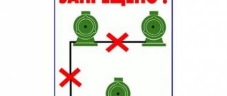
The most popular grounding connection schemes are:
Closed, in the shape of a triangle (Fig. 3). The main advantage is more stable and reliable operation. If the jumper between the rods is damaged, the circuit will still continue to work (but on the other side).
Rice. 3 Schematic diagram of a triangle
Linear (Fig. 4). Serial connection in one line of buried metal pegs. The disadvantage of such a circuit is that if the jumper fails, the circuit will not work.
Rice. 4 Schematic diagram of a linear view
In addition to the above types of contour diagrams, you can also use the following forms:
- rectangle;
- oval
Rice.
5 Shapes of ground loops Required tools and materials:
- welding machine;
- cutting tool (grinder);
- shovel;
- perforator;
- spanners;
- resistance meter;
- current meter;
- voltage meter.
In addition to the above devices, you must use:
- The corner is made of corrosion-resistant steel, its dimensions can be 50x50, 60x60 mm. Length – more than 2 meters. It is also possible to use a steel pipe with a diameter of at least 32 mm with a wall thickness of more than 3.5-4 mm.
- Metal strips (3 pieces). Their parameters: length – 120-130 cm; width – 4-6 cm; wall thickness – 4-6 mm.
- Steel strip made of stainless material 40x4, 50x5 mm. It connects the ground loop and the porch of the house.
- Bolts M10, M8.
- The conductor is copper, with a diameter of at least 6-7 mm2.
All the above parameters must be checked using a meter.